brakes OPEL CALIBRA 1988 Service User Guide
[x] Cancel search | Manufacturer: OPEL, Model Year: 1988, Model line: CALIBRA, Model: OPEL CALIBRA 1988Pages: 525, PDF Size: 58.26 MB
Page 151 of 525
Refitting
17Proceed as described in paragraphs 11
to 15 inclusive.
Models with rear disc brakes
(SOHC)
General
18The procedure is as described for models
with rear drum brakes, remembering the
following points.
19Ignore the references to removal and
refitting of the brake drum.
20Note that there is no lockplate securing
the handbrake cable to the brake backplate,
but the return spring must be unhooked from
the cable end.
21On models with a catalytic converter,
when removing the longer cable, unscrew the
four securing nuts and withdraw the exhaust
centre box heat shield by carefully sliding it
round the centre box.
DOHC models
Removal
22The left and right-hand handbrake cables,
and the equaliser yoke, are removed as an
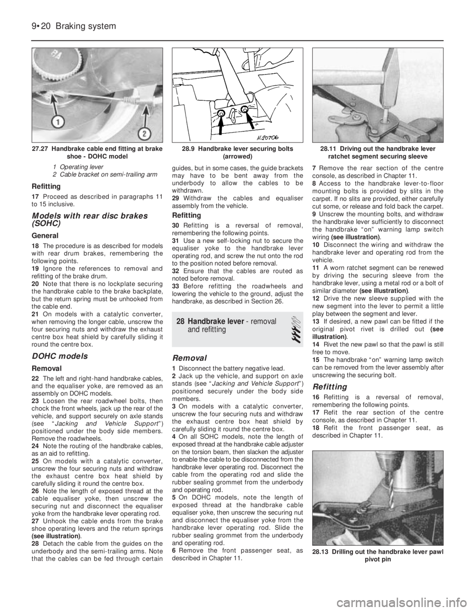
assembly on DOHC models.
23Loosen the rear roadwheel bolts, then
chock the front wheels, jack up the rear of the
vehicle, and support securely on axle stands
(see “Jacking and Vehicle Support”)
positioned under the body side members.
Remove the roadwheels.
24Note the routing of the handbrake cables,
as an aid to refitting.
25On models with a catalytic converter,
unscrew the four securing nuts and withdraw
the exhaust centre box heat shield by
carefully sliding it round the centre box.
26Note the length of exposed thread at the
cable equaliser yoke, then unscrew the
securing nut and disconnect the equaliser
yoke from the handbrake lever operating rod.
27Unhook the cable ends from the brake
shoe operating levers and the return springs
(see illustration).
28Detach the cable from the guides on the
underbody and the semi-trailing arms. Note
that the cables can be fed through certainguides, but in some cases, the guide brackets
may have to be bent away from the
underbody to allow the cables to be
withdrawn.
29Withdraw the cables and equaliser
assembly from the vehicle.
Refitting
30Refitting is a reversal of removal,
remembering the following points.
31Use a new self-locking nut to secure the
equaliser yoke to the handbrake lever
operating rod, and screw the nut onto the rod
to the position noted before removal.
32Ensure that the cables are routed as
noted before removal.
33Before refitting the roadwheels and
lowering the vehicle to the ground, adjust the
handbrake, as described in Section 26.
28Handbrake lever - removal
and refitting
3
Removal
1Disconnect the battery negative lead.
2Jack up the vehicle, and support on axle
stands (see “Jacking and Vehicle Support”)
positioned securely under the body side
members.
3On models with a catalytic converter,
unscrew the four securing nuts and withdraw
the exhaust centre box heat shield by
carefully sliding it round the centre box.
4On all SOHC models, note the length of
exposed thread at the handbrake cable adjuster
on the torsion beam, then slacken the adjuster
to enable the cable to be disconnected from the
handbrake lever operating rod. Disconnect the
cable from the operating rod and slide the
rubber sealing grommet from the underbody
and operating rod.
5On DOHC models, note the length of
exposed thread at the handbrake cable
equaliser yoke, then unscrew the securing nut
and disconnect the equaliser yoke from the
handbrake lever operating rod. Slide the
rubber sealing grommet from the underbody
and operating rod.
6Remove the front passenger seat, as
described in Chapter 11.7Remove the rear section of the centre
console, as described in Chapter 11.
8Access to the handbrake lever-to-floor
mounting bolts is provided by slits in the
carpet. If no slits are provided, either carefully
cut some, or release and fold back the carpet.
9Unscrew the mounting bolts, and withdraw
the handbrake lever sufficiently to disconnect
the handbrake “on” warning lamp switch
wiring (see illustration).
10Disconnect the wiring and withdraw the
handbrake lever and operating rod from the
vehicle.
11A worn ratchet segment can be renewed
by driving the securing sleeve from the
handbrake lever, using a metal rod or a bolt of
similar diameter (see illustration).
12Drive the new sleeve supplied with the
new segment into the lever to permit a little
play between the segment and lever.
13If desired, a new pawl can be fitted if the
original pivot rivet is drilled out (see
illustration).
14Rivet the new pawl so that the pawl is still
free to move.
15The handbrake “on” warning lamp switch
can be removed from the lever assembly after
unscrewing the securing bolt.
Refitting
16Refitting is a reversal of removal,
remembering the following points.
17Refit the rear section of the centre
console, as described in Chapter 11.
18Refit the front passenger seat, as
described in Chapter 11.
9•20Braking system
28.13 Drilling out the handbrake lever pawl
pivot pin
28.11 Driving out the handbrake lever
ratchet segment securing sleeve28.9 Handbrake lever securing bolts
(arrowed)27.27 Handbrake cable end fitting at brake
shoe - DOHC model
1 Operating lever
2 Cable bracket on semi-trailing arm
Page 174 of 525
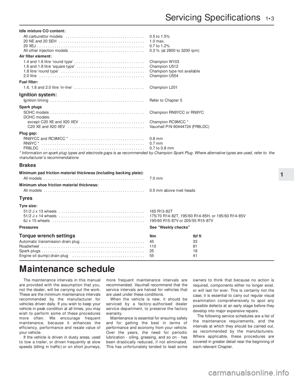
Idle mixture CO content:
All carburettor models . . . . . . . . . . . . . . . . . . . . . . . . . . . . . . . . . . . .0.5 to 1.5%
20 NE and 20 SEH . . . . . . . . . . . . . . . . . . . . . . . . . . . . . . . . . . . . . . .1.0 max.
20 XEJ . . . . . . . . . . . . . . . . . . . . . . . . . . . . . . . . . . . . . . . . . . . . . . . . .0.7 to 1.2%
All other injection models . . . . . . . . . . . . . . . . . . . . . . . . . . . . . . . . . .0.3 % (at 2800 to 3200 rpm)
Air filter element:
1.4 and 1.6 litre ‘round type’ . . . . . . . . . . . . . . . . . . . . . . . . . . . . . . . .Champion W103
1.6 and 1.8 litre ‘square type’ . . . . . . . . . . . . . . . . . . . . . . . . . . . . . . .Champion U512
1.8 litre ‘round type’ . . . . . . . . . . . . . . . . . . . . . . . . . . . . . . . . . . . . . .Champion type not available
2.0 litre . . . . . . . . . . . . . . . . . . . . . . . . . . . . . . . . . . . . . . . . . . . . . . . .Champion U554
Fuel filter:
1.6, 1.8 and 2.0 litre ‘in-line’ . . . . . . . . . . . . . . . . . . . . . . . . . . . . . . . .Champion L201
Ignition system:
Ignition timing . . . . . . . . . . . . . . . . . . . . . . . . . . . . . . . . . . . . . . . . . . .Refer to Chapter 5
Spark plugs
SOHC models . . . . . . . . . . . . . . . . . . . . . . . . . . . . . . . . . . . . . . . . . . .Champion RN9YCC or RN9YC
DOHC models:
except C20 XE and X20 XEV . . . . . . . . . . . . . . . . . . . . . . . . . . . . .Champion RC9MCC *
C20 XE and X20 XEV . . . . . . . . . . . . . . . . . . . . . . . . . . . . . . . . . . .Vauxhall P/N 90444724 (FR8LDC)
Plug gap:
RN9YCC and RC9MCC * . . . . . . . . . . . . . . . . . . . . . . . . . . . . . . . . . .0.8 mm
RN9YC * . . . . . . . . . . . . . . . . . . . . . . . . . . . . . . . . . . . . . . . . . . . . . . .0.7 mm
FR8LDC . . . . . . . . . . . . . . . . . . . . . . . . . . . . . . . . . . . . . . . . . . . . . . .0.7 to 0.8 mm
* Information on spark plug types and electrode gaps is as recommended by Champion Spark Plug. Where alternative types are used, refer to the
manufacturer’s recommendations
Brakes
Minimum pad friction material thickness (including backing plate):
All models . . . . . . . . . . . . . . . . . . . . . . . . . . . . . . . . . . . . . . . . . . . . . .7.0 mm
Minimum shoe friction material thickness:
All models . . . . . . . . . . . . . . . . . . . . . . . . . . . . . . . . . . . . . . . . . . . . . .0.5 mm above rivet heads
Tyres
Tyre size:
51/2 J x 13 wheels . . . . . . . . . . . . . . . . . . . . . . . . . . . . . . . . . . . . . . .165 R13-82T
51/2 J x 14 wheels . . . . . . . . . . . . . . . . . . . . . . . . . . . . . . . . . . . . . . .175/70 R14-82T, 195/60 R14-85H, or 195/60 R14-85V
6J x 15 wheels . . . . . . . . . . . . . . . . . . . . . . . . . . . . . . . . . . . . . . . . . .195/60 R15-87V or 205/55 R15-87V
PressuresSee “Weekly checks”
Torque wrench settingsNmlbf ft
Automatic transmission drain plug . . . . . . . . . . . . . . . . . . . . . . . . . . . . .4533
Roadwheel . . . . . . . . . . . . . . . . . . . . . . . . . . . . . . . . . . . . . . . . . . . . . . .11081
Spark plugs . . . . . . . . . . . . . . . . . . . . . . . . . . . . . . . . . . . . . . . . . . . . . . .2518
Engine oil (sump) drain plug . . . . . . . . . . . . . . . . . . . . . . . . . . . . . . . . .5541
Servicing Specifications 1•3
1
The maintenance intervals in this manual
are provided with the assumption that you,
not the dealer, will be carrying out the work.
These are the minimum maintenance intervals
recommended by the manufacturer for
vehicles driven daily. If you wish to keep your
vehicle in peak condition at all times, you may
wish to perform some of these procedures
more often. We encourage frequent
maintenance, because it enhances the
efficiency, performance and resale value of
your vehicle.
If the vehicle is driven in dusty areas, used
to tow a trailer, or driven frequently at slow
speeds (idling in traffic) or on short journeys,more frequent maintenance intervals are
recommended. Vauxhall recommend that the
service intervals are halved for vehicles that
are used under these conditions.
When the vehicle is new, it should be
serviced by a factory-authorised dealer
service department, to preserve the factory
warranty.
Maintenance is essential for ensuring safety
and for getting the best in terms of
performance and economy from your vehicle.
Over the years, the need for periodic
lubrication -oiling, greasing, and so on -has
been drastically reduced, if not eliminated.
This has unfortunately tended to lead someowners to think that because no action is
required, components either no longer exist,
or will last for ever. This is certainly not the
case; it is essential to carry out regular visual
examination comprehensively to spot any
possible defects at an early stage before they
develop into major expensive repairs.
The following service schedules are a list of
the maintenance requirements, and the
intervals at which they should be carried out,
as recommended by the manufacturers.
Where applicable, these procedures are
covered in greater detail near the beginning of
each relevant Chapter.
Maintenance schedule
Page 240 of 525
REF
Overall length: *
Saloon models . . . . . . . . . . . . . . . . . . . . . . . . . . . . . . . . . . .4432 mm
Hatchback models . . . . . . . . . . . . . . . . . . . . . . . . . . . . . . . .4352 mm
Overall width: *
All models . . . . . . . . . . . . . . . . . . . . . . . . . . . . . . . . . . . . . .1876 mm
Overall height (unladen): *
All models . . . . . . . . . . . . . . . . . . . . . . . . . . . . . . . . . . . . . .1400 mm
Wheelbase: *
All models . . . . . . . . . . . . . . . . . . . . . . . . . . . . . . . . . . . . . .2600 mm
Track:
Front: *
All models . . . . . . . . . . . . . . . . . . . . . . . . . . . . . . . . . . . .1426 mm
Rear: *
All models . . . . . . . . . . . . . . . . . . . . . . . . . . . . . . . . . . . .1423 mm
Ground clearance (minimum): *
All models . . . . . . . . . . . . . . . . . . . . . . . . . . . . . . . . . . . . . . . . .120 mm
Weights
Kerb weight: *
Dependent on model . . . . . . . . . . . . . . . . . . . . . . . . . .1098 ± 101 kg
Maximum gross vehicle weight: *
All models . . . . . . . . . . . . . . . . . . . . . . . . . . . . . . . .Refer to VIN plate
Maximum roof rack load: *
All models . . . . . . . . . . . . . . . . . . . . . . . . . . . . . . . . . . . . . . . .100 kg
Maximum towing hitch downward load: *
All models . . . . . . . . . . . . . . . . . . . . . . . . . . . . . . . . . . . . . . . . .75 kg
Maximum towing weight: *
Trailer with brakes . . . . . . . . . . . . . . . . . . . . . . . . . . . .1175 ± 175 kg
Trailer without brakes . . . . . . . . . . . . . . . . . . . . . . . . . . .550 ± 50 kg
* Exact details depend upon model and specification.
Refer to owners handbook.
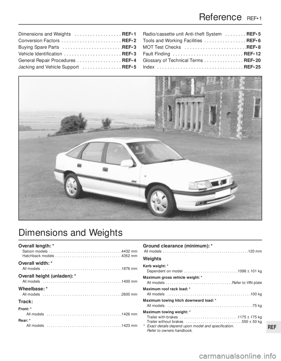
Dimensions and Weights . . . . . . . . . . . . . . . . . .REF•1
Conversion Factors . . . . . . . . . . . . . . . . . . . . . . .REF•2
Buying Spare Parts . . . . . . . . . . . . . . . . . . . . . . .REF•3
Vehicle Identification . . . . . . . . . . . . . . . . . . . . . .REF•3
General Repair Procedures . . . . . . . . . . . . . . . . .REF•4
Jacking and Vehicle Support . . . . . . . . . . . . . . .REF•5Radio/cassette unit Anti-theft System . . . . . . . .REF•5
Tools and Working Facilities . . . . . . . . . . . . . . . .REF•6
MOT Test Checks . . . . . . . . . . . . . . . . . . . . . . . .REF•8
Fault Finding . . . . . . . . . . . . . . . . . . . . . . . . . . .REF•12
Glossary of Technical Terms . . . . . . . . . . . . . . .REF•20
Index . . . . . . . . . . . . . . . . . . . . . . . . . . . . . . . . .REF•25
Reference REF•1
Dimensions and Weights
Page 251 of 525
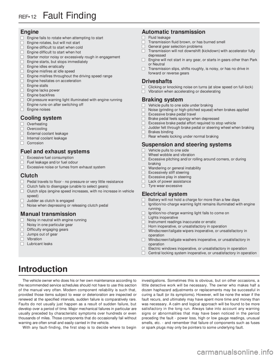
Engine
m mEngine fails to rotate when attempting to start
m mEngine rotates, but will not start
m mEngine difficult to start when cold
m mEngine difficult to start when hot
m mStarter motor noisy or excessively rough in engagement
m mEngine starts, but stops immediately
m mEngine idles erratically
m mEngine misfires at idle speed
m mEngine misfires throughout the driving speed range
m mEngine hesitates on acceleration
m mEngine stalls
m mEngine lacks power
m mEngine backfires
m mOil pressure warning light illuminated with engine running
m mEngine runs-on after switching off
m mEngine noises
Cooling system
m
mOverheating
m mOvercooling
m mExternal coolant leakage
m mInternal coolant leakage
m mCorrosion
Fuel and exhaust systems
m
mExcessive fuel consumption
m mFuel leakage and/or fuel odour
m mExcessive noise or fumes from exhaust system
Clutch
m
mPedal travels to floor - no pressure or very little resistance
m mClutch fails to disengage (unable to select gears)
m mClutch slips (engine speed increases, with no increase in vehicle
speed)
m mJudder as clutch is engaged
m mNoise when depressing or releasing clutch pedal
Manual transmission
m
mNoisy in neutral with engine running
m mNoisy in one particular gear
m mDifficulty engaging gears
m mJumps out of gear
m mVibration
m mLubricant leaks
Automatic transmission
m
mFluid leakage
m mTransmission fluid brown, or has burned smell
m mGeneral gear selection problems
m mTransmission will not downshift (kickdown) with accelerator fully
depressed
m mEngine will not start in any gear, or starts in gears other than Park
or Neutral
m mTransmission slips, shifts roughly, is noisy, or has no drive in
forward or reverse gears
Driveshafts
m mClicking or knocking noise on turns (at slow speed on full-lock)
m mVibration when accelerating or decelerating
Braking system
m
mVehicle pulls to one side under braking
m mNoise (grinding or high-pitched squeal) when brakes applied
m mExcessive brake pedal travel
m mBrake pedal feels spongy when depressed
m mExcessive brake pedal effort required to stop vehicle
m mJudder felt through brake pedal or steering wheel when braking
m mBrakes binding
m mRear wheels locking under normal braking
Suspension and steering systems
m
mVehicle pulls to one side
m mWheel wobble and vibration
m mExcessive pitching and/or rolling around corners, or during
braking
m mWandering or general instability
m mExcessively stiff steering
m mExcessive play in steering
m mLack of power assistance
m mTyre wear excessive
Electrical system
m
mBattery will not hold a charge for more than a few days
m mIgnition/no-charge warning light remains illuminated with engine
running
m mIgnition/no-charge warning light fails to come on
m mLights inoperative
m mInstrument readings inaccurate or erratic
m mHorn inoperative, or unsatisfactory in operation
m mWindscreen/tailgate wipers inoperative, or unsatisfactory in
operation
m mWindscreen/tailgate washers inoperative, or unsatisfactory in
operation
m mElectric windows inoperative, or unsatisfactory in operation
m mCentral locking system inoperative, or unsatisfactory in operation
The vehicle owner who does his or her own maintenance according to
the recommended service schedules should not have to use this section
of the manual very often. Modern component reliability is such that,
provided those items subject to wear or deterioration are inspected or
renewed at the specified intervals, sudden failure is comparatively rare.
Faults do not usually just happen as a result of sudden failure, but
develop over a period of time. Major mechanical failures in particular are
usually preceded by characteristic symptoms over hundreds or even
thousands of miles. Those components that do occasionally fail without
warning are often small and easily carried in the vehicle.
With any fault-finding, the first step is to decide where to begininvestigations. Sometimes this is obvious, but on other occasions, a
little detective work will be necessary. The owner who makes half a
dozen haphazard adjustments or replacements may be successful in
curing a fault (or its symptoms). However, will be none the wiser if the
fault recurs, and ultimately may have spent more time and money than
was necessary. A calm and logical approach will be found to be more
satisfactory in the long run. Always take into account any warning
signs or abnormalities that may have been noticed in the period
preceding the fault - power loss, high or low gauge readings, unusual
smells, etc. - and remember that failure of components such as fuses
or spark plugs may only be pointers to some underlying fault.
REF•12Fault Finding
Introduction
Page 253 of 525
MFaulty ignition coil (Chapter 5).
MUneven or low cylinder compressions (Chapter 2A).
MBlocked carburettor jet(s) or internal passages - carburettor
models (Chapter 4A).
MBlocked injector/fuel injection system fault - fuel-injected models
(Chapter 4B).
Engine hesitates on acceleration
MWorn, faulty or incorrectly gapped spark plugs (Chapter 1).
MVacuum leak at the carburettor/throttle body, inlet manifold or
associated hoses (Chapter 4A or 4B).
MBlocked carburettor jet(s) or internal passages - carburettor
models (Chapter 4A).
MBlocked injector/fuel injection system fault - fuel-injected models
(Chapter 4B).
Engine stalls
MVacuum leak at the carburettor/throttle body, inlet manifold or
associated hoses (Chapter 4A or 4B).
MFuel filter choked (Chapter 1).
MFuel pump faulty, or delivery pressure low (Chapter 4A or 4B).
MFuel tank vent blocked, or fuel pipes restricted (Chapter 4A or 4B).
MBlocked carburettor jet(s) or internal passages - carburettor
models (Chapter 4A).
MBlocked injector/fuel injection system fault - fuel-injected models
(Chapter 4B).
Engine lacks power
MTiming belt incorrectly fitted or tensioned (Chapter 2A or 2B).
MFuel filter choked (Chapter 1).
MFuel pump faulty, or delivery pressure low (Chapter 4A or 4B).
MUneven or low cylinder compressions (Chapter 2A).
MWorn, faulty or incorrectly gapped spark plugs (Chapter 1).
MVacuum leak at the carburettor/throttle body, inlet manifold or
associated hoses (Chapter 4A or 4B).
MBlocked carburettor jet(s) or internal passages - carburettor
models (Chapter 4A).
MBlocked injector/fuel injection system fault - fuel-injected models
(Chapter 4B).
MBrakes binding (Chapters 1 and 9).
MClutch slipping (Chapter 6).
Engine backfires
MTiming belt incorrectly fitted or tensioned (Chapter 2A or 2B).
MVacuum leak at the carburettor/throttle body, inlet manifold or
associated hoses (Chapter 4A or 4B).
MBlocked carburettor jet(s) or internal passages - carburettor
models (Chapter 4A).
MBlocked injector/fuel injection system fault - fuel-injected models
(Chapter 4B).
Oil pressure warning light illuminated with engine
running
MLow oil level, or incorrect oil grade (Chapter 1).
MFaulty oil pressure warning light switch (Chapter 12).
MWorn engine bearings and/or oil pump (Chapter 2A).
MHigh engine operating temperature (Chapter 3).
MOil pressure relief valve defective (Chapter 2A).
MOil pick-up strainer clogged (Chapter 2A).
Engine runs-on after switching off
MExcessive carbon build-up in engine (Chapter 2A).
MHigh engine operating temperature (Chapter 3).
MFaulty fuel cut-off solenoid - carburettor models (Chapter 4A).
MFuel injection system fault - fuel-injected models (Chapter 4B).
Engine noises
Pre-ignition (pinking) or knocking during acceleration or
under load
MIgnition timing incorrect/ignition system fault (Chapters 1 and 5).
MIncorrect grade of spark plug (Chapter 1).
MIncorrect grade of fuel (Chapter 1).
MVacuum leak at the carburettor/throttle body, inlet manifold or
associated hoses (Chapter 4A or 4B).
MExcessive carbon build-up in engine (Chapter 2A).
MBlocked carburettor jet(s) or internal passages - carburettor
models (Chapter 4A).
MBlocked injector/fuel injection system fault - fuel-injected models
(Chapter 4B).
Whistling or wheezing noises
MLeaking inlet manifold or carburettor/throttle body gasket
(Chapter 4A or 4B).
MLeaking exhaust manifold gasket or pipe-to-manifold joint
(Chapter 4C).
MLeaking vacuum hose (Chapters 4A, 4B, 4C, 5, 9 and 12).
MBlowing cylinder head gasket (Chapter 2A or 2B).
Tapping or rattling noises
MWorn valve gear or camshaft (Chapter 2A or 2B).
MAncillary component fault (coolant pump, alternator, etc.)
(Chapters 3, 5, etc.).
Knocking or thumping noises
MWorn big-end bearings (regular heavy knocking, perhaps less
under load), (Chapter 2A or 2B).
MWorn main bearings (rumbling and knocking, perhaps worsening
under load), (Chapter 2A or 2B).
MPiston slap (most noticeable when cold), (Chapter 2A).
MAncillary component fault (coolant pump, alternator, etc.)
(Chapters 3, 5, etc.).
REF•14Fault Finding
Engine (continued)
Page 256 of 525
Note:Before diagnosing suspension or steering faults, be sure that the
trouble is not due to incorrect tyre pressures, mixtures of tyre types, or
binding brakes.
Vehicle pulls to one side
MDefective tyre (Chapter 1).
MExcessive wear in suspension or steering components (Chapters 1
and 10).
MIncorrect front wheel alignment (Chapter 10).
MAccident damage to steering or suspension components
(Chapter 1).
Wheel wobble and vibration
MFront roadwheels out of balance (vibration felt mainly through the
steering wheel), (Chapters 1 and 10).
MRear roadwheels out of balance (vibration felt throughout the
vehicle), (Chapters 1 and 10).
MRoadwheels damaged or distorted (Chapters 1 and 10).
MFaulty or damaged tyre (Chapter 1).
MWorn steering or suspension joints, bushes or components
(Chapters 1 and 10).
MWheel bolts loose (Chapters 1 and 10).
Excessive pitching and/or rolling around corners,
or during braking
MDefective shock absorbers (Chapters 1 and 10).
MBroken or weak spring and/or suspension component (Chapters 1
and 10).
MWorn or damaged anti-roll bar or mountings (Chapter 10).
Wandering or general instability
MIncorrect front wheel alignment (Chapter 10).
MWorn steering or suspension joints, bushes or components
(Chapters 1 and 10).
MRoadwheels out of balance (Chapters 1 and 10).
MFaulty or damaged tyre (Chapter 1).
MWheel bolts loose (Chapters 1 and 10).
MDefective shock absorbers (Chapters 1 and 10).
Excessively stiff steering
MLack of steering gear lubricant (Chapter 10).
MSeized track rod end balljoint or suspension balljoint (Chapters 1
and 10).
MBroken or incorrectly adjusted auxiliary drivebelt - power steering
(Chapter 1).
Fault Finding REF•17
REF
Note:Before assuming that a brake problem exists, make sure that the
tyres are in good condition and correctly inflated, that the front wheel
alignment is correct, and that the vehicle is not loaded with weight in an
unequal manner. Apart from checking the condition of all pipe and
hose connections, any faults occurring on the anti-lock braking system
should be referred to a Peugeot dealer for diagnosis.
Vehicle pulls to one side under braking
MWorn, defective, damaged or contaminated brake pads/shoes on
one side (Chapters 1 and 9).
MSeized or partially seized front brake caliper/wheel cylinder piston
(Chapters 1 and 9).
MA mixture of brake pad/shoe lining materials fitted between sides
(Chapters 1 and 9).
MBrake caliper or backplate mounting bolts loose (Chapter 9).
MWorn or damaged steering or suspension components
(Chapters 1 and 10).
Noise (grinding or high-pitched squeal) when
brakes applied
MBrake pad or shoe friction lining material worn down to metal
backing (Chapters 1 and 9).
MExcessive corrosion of brake disc or drum. This may be apparent
after the vehicle has been standing for some time (Chapters 1 and 9).
MForeign object (stone chipping, etc.) trapped between brake disc
and shield (Chapters 1 and 9).
Excessive brake pedal travel
MInoperative rear brake self-adjust mechanism - drum brakes
(Chapters 1 and 9).
MFaulty master cylinder (Chapter 9).
MAir in hydraulic system (Chapters 1 and 9).
MFaulty vacuum servo unit (Chapter 9).
Brake pedal feels spongy when depressed
MAir in hydraulic system (Chapters 1 and 9).
MDeteriorated flexible rubber brake hoses (Chapters 1 and 9).
MMaster cylinder mounting nuts loose (Chapter 9).
MFaulty master cylinder (Chapter 9).
Excessive brake pedal effort required to stop
vehicle
MFaulty vacuum servo unit (Chapter 9).
MDisconnected, damaged or insecure brake servo vacuum hose
(Chapter 9).
MPrimary or secondary hydraulic circuit failure (Chapter 9).
MSeized brake caliper or wheel cylinder piston(s) (Chapter 9).
MBrake pads or brake shoes incorrectly fitted (Chapters 1 and 9).
MIncorrect grade of brake pads or brake shoes fitted (Chapters 1
and 9).
MBrake pads or brake shoe linings contaminated (Chapters 1 and 9).
Judder felt through brake pedal or steering wheel
when braking
MExcessive run-out or distortion of discs/drums (Chapters 1 and 9).
MBrake pad or brake shoe linings worn (Chapters 1 and 9).
MBrake caliper or brake backplate mounting bolts loose (Chapter 9).
MWear in suspension or steering components or mountings
(Chapters 1 and 10).
Brakes binding
MSeized brake caliper or wheel cylinder piston(s) (Chapter 9).
MIncorrectly adjusted handbrake mechanism (Chapter 9).
MFaulty master cylinder (Chapter 9).
Rear wheels locking under normal braking
MRear brake shoe linings contaminated (Chapters 1 and 9).
MFaulty brake pressure regulator (Chapter 9).
Braking system
Suspension and steering
Page 259 of 525
REF•20Glossary of Technical Terms
A
ABS (Anti-lock brake system)A system,
usually electronically controlled, that senses
incipient wheel lockup during braking and
relieves hydraulic pressure at wheels that are
about to skid.
Air bag An inflatable bag hidden in the
steering wheel (driver’s side) or the dash or
glovebox (passenger side). In a head-on
collision, the bags inflate, preventing the
driver and front passenger from being thrown
forward into the steering wheel or windscreen.
Air cleanerA metal or plastic housing,
containing a filter element, which removes
dust and dirt from the air being drawn into the
engine.
Air filter elementThe actual filter in an air
cleaner system, usually manufactured from
pleated paper and requiring renewal at regular
intervals.
Allen keyA hexagonal wrench which fits into
a recessed hexagonal hole.
Alligator clipA long-nosed spring-loaded
metal clip with meshing teeth. Used to make
temporary electrical connections.
AlternatorA component in the electrical
system which converts mechanical energy
from a drivebelt into electrical energy to
charge the battery and to operate the starting
system, ignition system and electrical
accessories.
Ampere (amp)A unit of measurement for the
flow of electric current. One amp is the
amount of current produced by one volt
acting through a resistance of one ohm.
Anaerobic sealerA substance used to
prevent bolts and screws from loosening.
Anaerobic means that it does not require
oxygen for activation. The Loctite brand is
widely used.
AntifreezeA substance (usually ethylene
glycol) mixed with water, and added to a
vehicle’s cooling system, to prevent freezing
of the coolant in winter. Antifreeze also
contains chemicals to inhibit corrosion and
the formation of rust and other deposits thatwould tend to clog the radiator and coolant
passages and reduce cooling efficiency.
Anti-seize compoundA coating that
reduces the risk of seizing on fasteners that
are subjected to high temperatures, such as
exhaust manifold bolts and nuts.
AsbestosA natural fibrous mineral with great
heat resistance, commonly used in the
composition of brake friction materials.
Asbestos is a health hazard and the dust
created by brake systems should never be
inhaled or ingested.
AxleA shaft on which a wheel revolves, or
which revolves with a wheel. Also, a solid
beam that connects the two wheels at one
end of the vehicle. An axle which also
transmits power to the wheels is known as a
live axle.
AxleshaftA single rotating shaft, on either
side of the differential, which delivers power
from the final drive assembly to the drive
wheels. Also called a driveshaft or a halfshaft.
BBall bearingAn anti-friction bearing
consisting of a hardened inner and outer race
with hardened steel balls between two races.BearingThe curved surface on a shaft or in a
bore, or the part assembled into either, that
permits relative motion between them with
minimum wear and friction.
Big-end bearingThe bearing in the end of
the connecting rod that’s attached to the
crankshaft.
Bleed nippleA valve on a brake wheel
cylinder, caliper or other hydraulic component
that is opened to purge the hydraulic system
of air. Also called a bleed screw.
Brake bleedingProcedure for removing air
from lines of a hydraulic brake system.
Brake discThe component of a disc brake
that rotates with the wheels.
Brake drumThe component of a drum brake
that rotates with the wheels.
Brake liningsThe friction material which
contacts the brake disc or drum to retard the
vehicle’s speed. The linings are bonded or
riveted to the brake pads or shoes.
Brake padsThe replaceable friction pads
that pinch the brake disc when the brakes are
applied. Brake pads consist of a friction
material bonded or riveted to a rigid backing
plate.
Brake shoeThe crescent-shaped carrier to
which the brake linings are mounted and
which forces the lining against the rotating
drum during braking.
Braking systemsFor more information on
braking systems, consult the Haynes
Automotive Brake Manual.
Breaker barA long socket wrench handle
providing greater leverage.
BulkheadThe insulated partition between
the engine and the passenger compartment.
CCaliperThe non-rotating part of a disc-brake
assembly that straddles the disc and carries
the brake pads. The caliper also contains the
hydraulic components that cause the pads to
pinch the disc when the brakes are applied. A
caliper is also a measuring tool that can be set
to measure inside or outside dimensions of an
object.
Brake bleeding
Bearing
Axle assembly
Anti-seize compound
Alternator (exploded view)
Air filter
Page 261 of 525
REF•22Glossary of Technical Terms
EEGR valveA valve used to introduce exhaust
gases into the intake air stream.
Electronic control unit (ECU)A computer
which controls (for instance) ignition and fuel
injection systems, or an anti-lock braking
system. For more information refer to the
Haynes Automotive Electrical and Electronic
Systems Manual.
Electronic Fuel Injection (EFI)A computer
controlled fuel system that distributes fuel
through an injector located in each intake port
of the engine.
Emergency brakeA braking system,
independent of the main hydraulic system,
that can be used to slow or stop the vehicle if
the primary brakes fail, or to hold the vehicle
stationary even though the brake pedal isn’t
depressed. It usually consists of a hand lever
that actuates either front or rear brakes
mechanically through a series of cables and
linkages. Also known as a handbrake or
parking brake.
EndfloatThe amount of lengthwise
movement between two parts. As applied to a
crankshaft, the distance that the crankshaft
can move forward and back in the cylinder
block.
Engine management system (EMS)A
computer controlled system which manages
the fuel injection and the ignition systems in
an integrated fashion.
Exhaust manifoldA part with several
passages through which exhaust gases leave
the engine combustion chambers and enter
the exhaust pipe.
FFan clutchA viscous (fluid) drive coupling
device which permits variable engine fan
speeds in relation to engine speeds.Feeler bladeA thin strip or blade of hardened
steel, ground to an exact thickness, used to
check or measure clearances between parts.
Firing orderThe order in which the engine
cylinders fire, or deliver their power strokes,
beginning with the number one cylinder.
Flywheel A heavy spinning wheel in which
energy is absorbed and stored by means of
momentum. On cars, the flywheel is attached
to the crankshaft to smooth out firing
impulses.
Free playThe amount of travel before any
action takes place. The “looseness” in a
linkage, or an assembly of parts, between the
initial application of force and actual
movement. For example, the distance the
brake pedal moves before the pistons in the
master cylinder are actuated.
FuseAn electrical device which protects a
circuit against accidental overload. The typical
fuse contains a soft piece of metal which is
calibrated to melt at a predetermined current
flow (expressed as amps) and break the
circuit.
Fusible linkA circuit protection device
consisting of a conductor surrounded by
heat-resistant insulation. The conductor is
smaller than the wire it protects, so it acts as
the weakest link in the circuit. Unlike a blown
fuse, a failed fusible link must frequently be
cut from the wire for replacement.
GGapThe distance the spark must travel in
jumping from the centre electrode to the sideelectrode in a spark plug. Also refers to the
spacing between the points in a contact
breaker assembly in a conventional points-
type ignition, or to the distance between the
reluctor or rotor and the pickup coil in an
electronic ignition.
GasketAny thin, soft material - usually cork,
cardboard, asbestos or soft metal - installed
between two metal surfaces to ensure a good
seal. For instance, the cylinder head gasket
seals the joint between the block and the
cylinder head.
GaugeAn instrument panel display used to
monitor engine conditions. A gauge with a
movable pointer on a dial or a fixed scale is an
analogue gauge. A gauge with a numerical
readout is called a digital gauge.
HHalfshaftA rotating shaft that transmits
power from the final drive unit to a drive
wheel, usually when referring to a live rear
axle.
Harmonic balancerA device designed to
reduce torsion or twisting vibration in the
crankshaft. May be incorporated in the
crankshaft pulley. Also known as a vibration
damper.
HoneAn abrasive tool for correcting small
irregularities or differences in diameter in an
engine cylinder, brake cylinder, etc.
Hydraulic tappetA tappet that utilises
hydraulic pressure from the engine’s
lubrication system to maintain zero clearance
(constant contact with both camshaft and
valve stem). Automatically adjusts to variation
in valve stem length. Hydraulic tappets also
reduce valve noise.
IIgnition timingThe moment at which the
spark plug fires, usually expressed in the
number of crankshaft degrees before the
piston reaches the top of its stroke.
Inlet manifoldA tube or housing with
passages through which flows the air-fuel
mixture (carburettor vehicles and vehicles with
throttle body injection) or air only (port fuel-
injected vehicles) to the port openings in the
cylinder head.
Exhaust manifold
Feeler blade
Adjusting spark plug gap
Gasket
EGR valve
Page 262 of 525
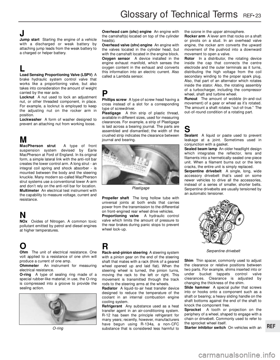
Glossary of Technical Terms REF•23
JJump startStarting the engine of a vehicle
with a discharged or weak battery by
attaching jump leads from the weak battery to
a charged or helper battery.
LLoad Sensing Proportioning Valve (LSPV)A
brake hydraulic system control valve that
works like a proportioning valve, but also
takes into consideration the amount of weight
carried by the rear axle.
LocknutA nut used to lock an adjustment
nut, or other threaded component, in place.
For example, a locknut is employed to keep
the adjusting nut on the rocker arm in
position.
LockwasherA form of washer designed to
prevent an attaching nut from working loose.
MMacPherson strutA type of front
suspension system devised by Earle
MacPherson at Ford of England. In its original
form, a simple lateral link with the anti-roll bar
creates the lower control arm. A long strut - an
integral coil spring and shock absorber - is
mounted between the body and the steering
knuckle. Many modern so-called MacPherson
strut systems use a conventional lower A-arm
and don’t rely on the anti-roll bar for location.
MultimeterAn electrical test instrument with
the capability to measure voltage, current and
resistance.
NNOxOxides of Nitrogen. A common toxic
pollutant emitted by petrol and diesel engines
at higher temperatures.
OOhmThe unit of electrical resistance. One
volt applied to a resistance of one ohm will
produce a current of one amp.
OhmmeterAn instrument for measuring
electrical resistance.
O-ringA type of sealing ring made of a
special rubber-like material; in use, the O-ring
is compressed into a groove to provide the
sealing action.Overhead cam (ohc) engineAn engine with
the camshaft(s) located on top of the cylinder
head(s).
Overhead valve (ohv) engineAn engine with
the valves located in the cylinder head, but
with the camshaft located in the engine block.
Oxygen sensorA device installed in the
engine exhaust manifold, which senses the
oxygen content in the exhaust and converts
this information into an electric current. Also
called a Lambda sensor.
PPhillips screwA type of screw head having a
cross instead of a slot for a corresponding
type of screwdriver.
PlastigageA thin strip of plastic thread,
available in different sizes, used for measuring
clearances. For example, a strip of Plastigage
is laid across a bearing journal. The parts are
assembled and dismantled; the width of the
crushed strip indicates the clearance between
journal and bearing.
Propeller shaftThe long hollow tube with
universal joints at both ends that carries
power from the transmission to the differential
on front-engined rear wheel drive vehicles.
Proportioning valveA hydraulic control
valve which limits the amount of pressure to
the rear brakes during panic stops to prevent
wheel lock-up.
RRack-and-pinion steeringA steering system
with a pinion gear on the end of the steering
shaft that mates with a rack (think of a geared
wheel opened up and laid flat). When the
steering wheel is turned, the pinion turns,
moving the rack to the left or right. This
movement is transmitted through the track
rods to the steering arms at the wheels.
RadiatorA liquid-to-air heat transfer device
designed to reduce the temperature of the
coolant in an internal combustion engine
cooling system.
RefrigerantAny substance used as a heat
transfer agent in an air-conditioning system.
R-12 has been the principle refrigerant for
many years; recently, however, manufacturers
have begun using R-134a, a non-CFC
substance that is considered less harmful tothe ozone in the upper atmosphere.
Rocker armA lever arm that rocks on a shaft
or pivots on a stud. In an overhead valve
engine, the rocker arm converts the upward
movement of the pushrod into a downward
movement to open a valve.
RotorIn a distributor, the rotating device
inside the cap that connects the centre
electrode and the outer terminals as it turns,
distributing the high voltage from the coil
secondary winding to the proper spark plug.
Also, that part of an alternator which rotates
inside the stator. Also, the rotating assembly
of a turbocharger, including the compressor
wheel, shaft and turbine wheel.
RunoutThe amount of wobble (in-and-out
movement) of a gear or wheel as it’s rotated.
The amount a shaft rotates “out-of-true.” The
out-of-round condition of a rotating part.
SSealantA liquid or paste used to prevent
leakage at a joint. Sometimes used in
conjunction with a gasket.
Sealed beam lampAn older headlight design
which integrates the reflector, lens and
filaments into a hermetically-sealed one-piece
unit. When a filament burns out or the lens
cracks, the entire unit is simply replaced.
Serpentine drivebeltA single, long, wide
accessory drivebelt that’s used on some
newer vehicles to drive all the accessories,
instead of a series of smaller, shorter belts.
Serpentine drivebelts are usually tensioned by
an automatic tensioner.
ShimThin spacer, commonly used to adjust
the clearance or relative positions between
two parts. For example, shims inserted into or
under bucket tappets control valve
clearances. Clearance is adjusted by
changing the thickness of the shim.
Slide hammerA special puller that screws
into or hooks onto a component such as a
shaft or bearing; a heavy sliding handle on the
shaft bottoms against the end of the shaft to
knock the component free.
SprocketA tooth or projection on the
periphery of a wheel, shaped to engage with a
chain or drivebelt. Commonly used to refer to
the sprocket wheel itself.
Starter inhibitor switchOn vehicles with an
O-ring
Serpentine drivebelt
Plastigage
REF
Page 264 of 525
AABS components- 9•2, 9•16
Accelerator cable- 4A•5, 4B•9
Accelerator pedal- 4A•5
Acknowledgements- 0•4
Aerial- 12•17
Air cleaner- 1•3, 1•13, 4A•3, 4B•4
Air box- 4B•5
Air pump/cut off valve- 4C•2
Air temp control- 4B•5
Air vents- 3•8
Airbag- 12•19
Airflow meters- 4B•12
Alternator- 5•5
Alternator V-belt check- 1•12
Anti theft alarm- 12•19
Anti-roll bars- 10•8, 10•13, 10•17
Antifreeze mixture- 0•12, 0•17, 1•2, 3•3
ATF- 0•17, 1•2, 1•11, 7B•3
Automatic choke unit- 4A•9
Automatic transmission- 7B•1 et seq
cooler pipes and hoses - 7B•5
ECU - 7B•5
fault diagnosis - REF•12, REF•16
fluid - 0•17, 1•2, 1•11, 7B•3
kickdown switch - 7B•3
removal and refitting - 7B•6
selector control cable - 7B•4
speed sensors - 7B•6
starter inhibitor switch - 7B•3
temperature sensor - 7B•5
BBattery- 0•6, 0•15, 5•5
Bearings (engine)- 2A•31
Bleeding the brakes- 9•3
Bleeding the power steering- 10•22
Blower motor- 3•7
Body damage- 11•2
Body electrical systems - 12•1 et seq
Bodywork and fittings- 11•1 et seq
Bonnet- 11•4
Bonnet lock/release cable- 11•4
Boot lid- 11•4
Boot lid lock- 11•5
Bores- 2A•33
Brake checks- 1•12,
Braking system- 9•1 et seq
ABS components - 9•2, 9•16
backplate - 9•12
bleeding the brakes - 9•3
brake caliper - 9•8
brake disc - 9•10
brake drum - 9•11
brake fluid pipes and hoses - 9•18
brake lamp switch - 12•5
brake pads - 9•4
brake pedal - 9•21
brake shoes - 9•6
disc shield - 9•13
fault diagnosis - REF•12, REF•17
fluid - 0•13, 0•17handbrake adjustment - 9•18
handbrake cables - 9•19
handbrake lever - 9•20
master cylinder - 9•13
pressure valves - 9•18
vacuum servo unit - 9•15
wheel cylinder - 9•11
Bulbs- 12•2, 12•7, 12•11
Bumpers- 11•11
CCables:
bonnet release - 11•4
clutch - 6•2
handbrake - 9•19
selector automatic transmission - 7B•4
speedometer - 12•18
throttle - 4A•5, 4B•9
Caliper (brake)- 9•8
Camber- 10•1, 10•24
Camshaft- 2A•19, 2B•6
Camshaft housing- 2A•18
Camshaft oil seals- 2A•18
Capacities- 1•2
Carbon canister- 4C•4
Carburettor- 4A•5, 4A•11
Carpets- 11•2
Castor- 10•1, 10•24
Catalytic converter- 4C•3
Central door locking- 12•16
Centre console- 11•18
Cigarette lighter- 12•5
Clock- 12•6
Clutch- 6•1 et seq
cable - 6•2
fault diagnosis - REF•12, REF•15
pedal - 6•3
release bearing - 6•6
removal, inspection and refitting - 6•3
Coil- 5•9
Coil spring (rear)- 10•12, 10•15
Compression test- 2A•8
Computer components- 12•7
Connecting rods- 2A•29
Contents- 0•2
Control units- 4B•16, 7B•5
Conversion factors- REF•2
Coolant- 0•12, 0•17, 1•2, 3•3
Cooling, heating and ventilation systems-
3•1 et seq
blower motor - 3•7
coolant level sensor - 3•5
coolant pump - 3•4
cooling fan - 3•5
draining - 3•2
expansion tank - 3•5
fan switch - 3•6
fault diagnosis - REF•12, REF•15
filling - 3•2
flushing - 3•2
heater control panel - 3•6
heater matrix - 3•7
radiator - 3•3temperature gauge sender - 3•6
thermostat - 3•4
vents - 3•8
Courtesy lamp switch- 12•5
Crankcase ventilation system- 2A•7
Crankshaft- 2A•31
Crankshaft oil seals- 2A•26, 2B•6, 2B•9
Cylinder bores- 2A•33
Cylinder head- 2A•19, 2A•22, 2B•7DDents- 11•2
Depressurising fuel system- 4B•5
Differential bearing oil seal- 7A•3
Dimensions and weights- REF•1
Disc (brake)- 9•10
Distributor- 5•10
Door- 11•6
handle - 11•7
inner trim panel - 11•6
lock key battery - 1•13
mirror - 11•11
Driveshafts- 8•1 et seq
fault diagnosis - REF•12, REF•16
gaiter - 8•4
joint renewal - 8•4
Drum (brake)- 9•11
EEarth fault finding- 12•2
ECU’s - 4B•16, 7B•5
EGR components- 4C•2
Electric windows- 12•15
Electrical fault finding- 12•2
Electrical system (body)- 12•1 et seq
Electrical system- 0•14, 5•2
Electrical system fault diagnosis- REF•12,
REF•18
Electronic control units- 4B•16, 7B•5
Engine:
bearings - 2A•31
camshaft - 2A•19, 2B•6
camshaft housing - 2A•18
camshaft oil seals - 2A•18, 2B•6
codes - 2A•1, 2B•1
compartment - 0•10, 1•5
compression test - 2A•8
connecting rods - 2A•29
crankcase ventilation - 2A•7
crankshaft - 2A•31
crankshaft oil seals - 2A•26, 2B•6, 2B•9
cylinder bores - 2A•33
cylinder head - 2A•19, 2A•22, 2B•7
dismantling - 2A•12
DOHC - 2B•1 et seq
electrical systems - 5•1 et seq
fault diagnosis - REF•12, REF•13
flexplate (automatic transmission) - 2A•26
flywheel - 2A•26
main and big-end bearings - 2A•31
mountings (engine/transmission) - 2A•12,
2B•3
Index REF•25
REF
Note:References throughout this index are in the form - “Chapter number” • “page number”