torque OPEL CALIBRA 1988 Service Owner's Guide
[x] Cancel search | Manufacturer: OPEL, Model Year: 1988, Model line: CALIBRA, Model: OPEL CALIBRA 1988Pages: 525, PDF Size: 58.26 MB
Page 183 of 525
14Brake fluid renewal
3
Renew the brake and bleed the system.
Refer to Chapter 9 for full details.
15Brake pad check
2
With the front or rear (as applicable) of the
vehicle raised, remove the wheels and check
brake pads for wear. Renew the pads if the
lining is below that specified. See Chapter 9,
for specifications and full details.
16Handbrake linkage check
2
With the vehicle raised, check the operation
of the handbrake and lubricate the linkages.
Refer to Chapter 9, for further details.
17Power steering fluid check
2
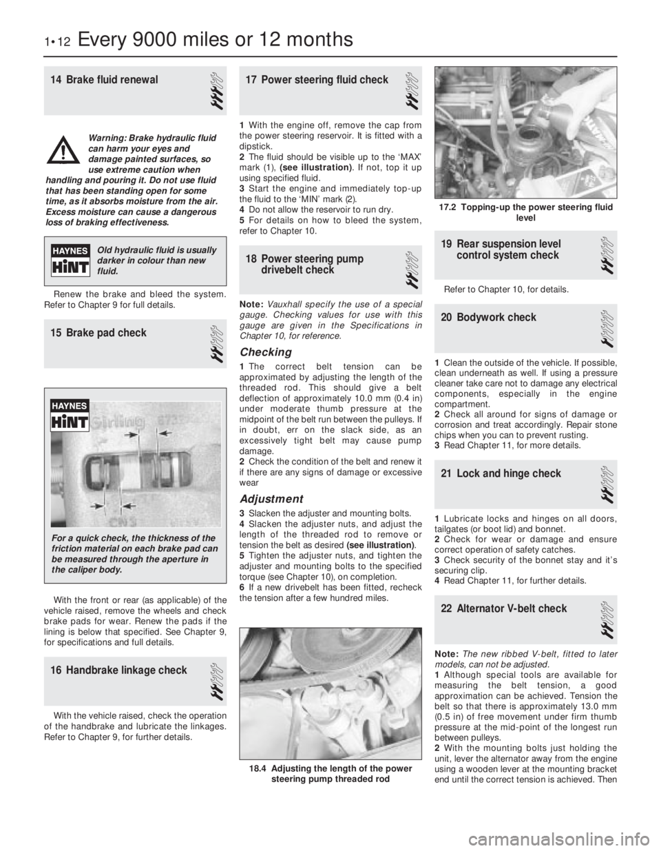
1With the engine off, remove the cap from
the power steering reservoir. It is fitted with a
dipstick.
2The fluid should be visible up to the ‘MAX’
mark (1), (see illustration). If not, top it up
using specified fluid.
3Start the engine and immediately top-up
the fluid to the ‘MIN’ mark (2).
4Do not allow the reservoir to run dry.
5For details on how to bleed the system,
refer to Chapter 10.
18Power steering pump
drivebelt check
2
Note:Vauxhall specify the use of a special
gauge. Checking values for use with this
gauge are given in the Specifications in
Chapter 10, for reference.
Checking
1The correct belt tension can be
approximated by adjusting the length of the
threaded rod. This should give a belt
deflection of approximately 10.0 mm (0.4 in)
under moderate thumb pressure at the
midpoint of the belt run between the pulleys. If
in doubt, err on the slack side, as an
excessively tight belt may cause pump
damage.
2Check the condition of the belt and renew it
if there are any signs of damage or excessive
wear
Adjustment
3Slacken the adjuster and mounting bolts.
4Slacken the adjuster nuts, and adjust the
length of the threaded rod to remove or
tension the belt as desired (see illustration).
5Tighten the adjuster nuts, and tighten the
adjuster and mounting bolts to the specified
torque (see Chapter 10), on completion.
6If a new drivebelt has been fitted, recheck
the tension after a few hundred miles.
19Rear suspension level
control system check
2
Refer to Chapter 10, for details.
20Bodywork check
1
1Clean the outside of the vehicle. If possible,
clean underneath as well. If using a pressure
cleaner take care not to damage any electrical
components, especially in the engine
compartment.
2Check all around for signs of damage or
corrosion and treat accordingly. Repair stone
chips when you can to prevent rusting.
3Read Chapter 11, for more details.
21Lock and hinge check
2
1Lubricate locks and hinges on all doors,
tailgates (or boot lid) and bonnet.
2Check for wear or damage and ensure
correct operation of safety catches.
3Check security of the bonnet stay and it’s
securing clip.
4Read Chapter 11, for further details.
22Alternator V-belt check
2
Note:The new ribbed V-belt, fitted to later
models, can not be adjusted.
1Although special tools are available for
measuring the belt tension, a good
approximation can be achieved. Tension the
belt so that there is approximately 13.0 mm
(0.5 in) of free movement under firm thumb
pressure at the mid-point of the longest run
between pulleys.
2With the mounting bolts just holding the
unit, lever the alternator away from the engine
using a wooden lever at the mounting bracket
end until the correct tension is achieved. Then
1•12Every 9000 miles or 12 months
17.2 Topping-up the power steering fluid
level
18.4 Adjusting the length of the power
steering pump threaded rod
Warning: Brake hydraulic fluid
can harm your eyes and
damage painted surfaces, so
use extreme caution when
handling and pouring it. Do not use fluid
that has been standing open for some
time, as it absorbs moisture from the air.
Excess moisture can cause a dangerous
loss of braking effectiveness.
Old hydraulic fluid is usually
darker in colour than new
fluid.
For a quick check, the thickness of the
friction material on each brake pad can
be measured through the aperture in
the caliper body.
Page 185 of 525
28Air inlet temperature control
check (carburettor models
only)
2
Refer to Chapter 4A for details.
29Fuel filter renewal
3
Fuel filters are fitted in various locations
throughout the range. Some may be ‘in-line’ in
the fuel tank itself, or fitted into the
carburettor.
Refer to Chapters 4A or 4B, as appropriate.
30Spark plug renewal (SOHC)
2
1The correct functioning of the spark plugs is
vital for the correct running and efficiency of
the engine. It is essential that the plugs fitted
are appropriate for the engine. Refer to the
specifications in Chapter 5. If this type is used
and the engine is in good condition, the spark
plugs should not need attention between
scheduled service replacement intervals.
Spark plug cleaning is rarely necessary and
should not be attempted unless specialised
equipment is available, as damage can easily
be caused to the firing ends.
2Identify each HT lead for position so that the
leads can be refitted to their correct cylinders.
Then disconnect the leads from the plugs by
pulling on the connectors, not the leads.
3Clean the area around each spark plug
using a small paintbrush, then using a plugspanner (preferably with a rubber insert),
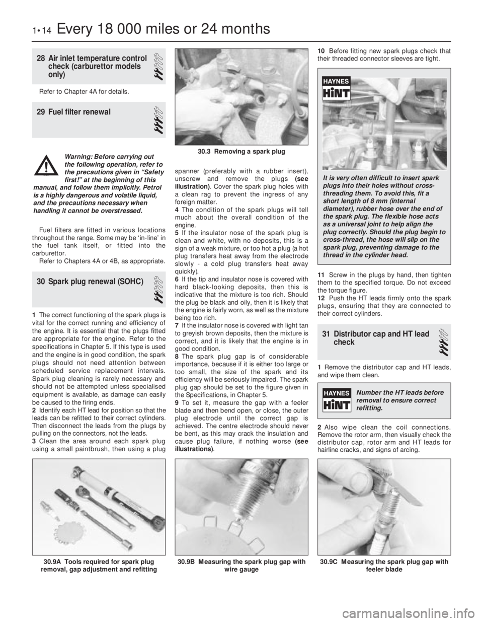
unscrew and remove the plugs (see
illustration). Cover the spark plug holes with
a clean rag to prevent the ingress of any
foreign matter.
4The condition of the spark plugs will tell
much about the overall condition of the
engine.
5If the insulator nose of the spark plug is
clean and white, with no deposits, this is a
sign of a weak mixture, or too hot a plug (a hot
plug transfers heat away from the electrode
slowly -a cold plug transfers heat away
quickly).
6If the tip and insulator nose is covered with
hard black-looking deposits, then this is
indicative that the mixture is too rich. Should
the plug be black and oily, then it is likely that
the engine is fairly worn, as well as the mixture
being too rich.
7If the insulator nose is covered with light tan
to greyish brown deposits, then the mixture is
correct, and it is likely that the engine is in
good condition.
8The spark plug gap is of considerable
importance, because if it is either too large or
too small, the size of the spark and its
efficiency will be seriously impaired. The spark
plug gap should be set to the figure given in
the Specifications, in Chapter 5.
9To set it, measure the gap with a feeler
blade and then bend open, or close, the outer
plug electrode until the correct gap is
achieved. The centre electrode should never
be bent, as this may crack the insulation and
cause plug failure, if nothing worse (see
illustrations).10Before fitting new spark plugs check that
their threaded connector sleeves are tight.
11Screw in the plugs by hand, then tighten
them to the specified torque. Do not exceed
the torque figure.
12Push the HT leads firmly onto the spark
plugs, ensuring that they are connected to
their correct cylinders.
31Distributor cap and HT lead
check
3
1Remove the distributor cap and HT leads,
and wipe them clean.
2Also wipe clean the coil connections.
Remove the rotor arm, then visually check the
distributor cap, rotor arm and HT leads for
hairline cracks, and signs of arcing.
1•14Every 18 000 miles or 24 months
30.9A Tools required for spark plug
removal, gap adjustment and refitting30.9C Measuring the spark plug gap with
feeler blade30.9B Measuring the spark plug gap with
wire gauge
30.3 Removing a spark plugWarning: Before carrying out
the following operation, refer to
the precautions given in “Safety
first!” at the beginning of this
manual, and follow them implicitly. Petrol
is a highly dangerous and volatile liquid,
and the precautions necessary when
handling it cannot be overstressed.
It is very often difficult to insert spark
plugs into their holes without cross-
threading them. To avoid this, fit a
short length of 8 mm (internal
diameter), rubber hose over the end of
the spark plug. The flexible hose acts
as a universal joint to help align the
plug correctly. Should the plug begin to
cross-thread, the hose will slip on the
spark plug, preventing damage to the
thread in the cylinder head.
Number the HT leads before
removal to ensure correct
refitting.
Page 187 of 525
36Timing belt renewal
3
1To minimise risk of major damage to the
engine the timing belt (or cambelt, as it is
sometimes called), needs replacing at least,
on every major service.
2It is good practise however, not only to
renew the belt whenever major engine work is
carried out, but also if you buy a used car with
unclear service history.
3Some models are fitted with an inspection
cover to view the condition of the belt. Whilst
others involve a lot more work.
4Full details on checking and replacement
are shown in Chapters 2A or 2B, as
appropriate.
37Spark plug renewal (DOHC)
2
1This procedure is basically the same shown
in Section 30. However on these models, a
spark plug cover needs to be removed from
the camshaft cover before the plugs can be
removed.
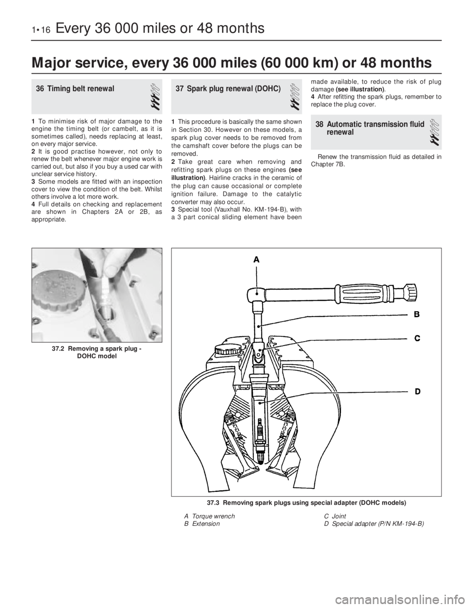
2Take great care when removing and
refitting spark plugs on these engines (see
illustration). Hairline cracks in the ceramic of
the plug can cause occasional or complete
ignition failure. Damage to the catalytic
converter may also occur.
3Special tool (Vauxhall No. KM-194-B), with
a 3 part conical sliding element have beenmade available, to reduce the risk of plug
damage (see illustration).
4After refitting the spark plugs, remember to
replace the plug cover.38Automatic transmission fluid
renewal
2
Renew the transmission fluid as detailed in
Chapter 7B.
1•16Every 36 000 miles or 48 months
37.3 Removing spark plugs using special adapter (DOHC models)
A Torque wrench
B ExtensionC Joint
D Special adapter (P/N KM-194-B)
37.2 Removing a spark plug -
DOHC model
Major service, every 36 000 miles (60 000 km) or 48 months
Page 188 of 525
2B
Note:All specifications as for 2.0 litre SOHC engines, unless shown otherwise
General
Type (all models) . . . . . . . . . . . . . . . . . . . . . . . . . . . . . . . . . . . . . . . . . . . Four-cylinder, in-line, water-cooled, transversely mounted. Double
belt-driven overhead camshafts, acting on hydraulic valve lifters
Manufacturer’s engine codes:
20 XEJ . . . . . . . . . . . . . . . . . . . . . . . . . . . . . . . . . . . . . . . . . . . . . . . . . 2.0 litre (1998 cc)
C20 XE . . . . . . . . . . . . . . . . . . . . . . . . . . . . . . . . . . . . . . . . . . . . . . . . 2.0 litre (1998 cc) + catalyst
X20 XEV . . . . . . . . . . . . . . . . . . . . . . . . . . . . . . . . . . . . . . . . . . . . . . . 2.0 litre (1998 cc) + catalyst. ‘Ecotec’ type engine
Compression ratio:
20 XEJ and C20 XE . . . . . . . . . . . . . . . . . . . . . . . . . . . . . . . . . . . . . . . 10.5 : 1
X20 XEV . . . . . . . . . . . . . . . . . . . . . . . . . . . . . . . . . . . . . . . . . . . . . . . 10.8 : 1
Maximum power:
20 XEJ and C20 XE . . . . . . . . . . . . . . . . . . . . . . . . . . . . . . . . . . . . . . . 110 kW (150 bhp) at 6000 rpm
X20 XEV . . . . . . . . . . . . . . . . . . . . . . . . . . . . . . . . . . . . . . . . . . . . . . . 100 kW (136 bhp) at 5400 rpm
Maximum torque:
20 XEJ . . . . . . . . . . . . . . . . . . . . . . . . . . . . . . . . . . . . . . . . . . . . . . . . . 196 Nm at 4800 rpm
C20 XE
Up to model year 1993 . . . . . . . . . . . . . . . . . . . . . . . . . . . . . . . . . . 196 Nm at 4800 rpm
1993-on . . . . . . . . . . . . . . . . . . . . . . . . . . . . . . . . . . . . . . . . . . . . . . 196 Nm at 4600 rpm
X20 XEV . . . . . . . . . . . . . . . . . . . . . . . . . . . . . . . . . . . . . . . . . . . . . . . 185 Nm at 4000 rpm
Cylinder Head
Overall height of cylinder head (sealing surface to sealing surface):
20 XEJ and C20 XE . . . . . . . . . . . . . . . . . . . . . . . . . . . . . . . . . . . . . . . 135.58 to 135.68 mm
X20 XEV . . . . . . . . . . . . . . . . . . . . . . . . . . . . . . . . . . . . . . . . . . . . . . . 134.00 mm
Installation height of valve guide:
20 XEJ and C20 XE . . . . . . . . . . . . . . . . . . . . . . . . . . . . . . . . . . . . . . . 10.70 to 11.00 mm
X20 XEV . . . . . . . . . . . . . . . . . . . . . . . . . . . . . . . . . . . . . . . . . . . . . . . 13.70 to 14.00 mm
Camshaft
Camshaft bearing journal diameter (all models) . . . . . . . . . . . . . . . . . . . 27.939 to 27.960 mm
Camshaft bearing diameter in housing (all models) . . . . . . . . . . . . . . . . 28.000 to 28.021 mm
Cam lift:
20 XEJ and C20 XE . . . . . . . . . . . . . . . . . . . . . . . . . . . . . . . . . . . . . . . 9.5 mm
X20 XEV . . . . . . . . . . . . . . . . . . . . . . . . . . . . . . . . . . . . . . . . . . . . . . . 10.0 mm
Maximum permissible radial run-out:
20 XEJ and C20 XE . . . . . . . . . . . . . . . . . . . . . . . . . . . . . . . . . . . . . . . 0.04 mm
X20 XEV . . . . . . . . . . . . . . . . . . . . . . . . . . . . . . . . . . . . . . . . . . . . . . . 0.06 mm
Endfloat (all models) . . . . . . . . . . . . . . . . . . . . . . . . . . . . . . . . . . . . . . . . 0.040 to 0.144 mm
Chapter 2 Part B:
DOHC engine procedures
Camshaft front oil seal - removal and refitting . . . . . . . . . . . . . . . . . . .6
Camshafts - removal, inspection and refitting . . . . . . . . . . . . . . . . . . .7
Crankshaft front oil seal - renewal . . . . . . . . . . . . . . . . . . . . . . . . . . .12
Cylinder head - dismantling and reassembly . . . . . . . . . . . . . . . . . . .10
Cylinder head - removal and refitting (engine in vehicle) . . . . . . . . . . .8
Cylinder head - removal and refitting (engine removed) . . . . . . . . . . . .9
Engine - removal and refitting . . . . . . . . . . . . . . . . . . . . . . . . . . . . . . .2
Engine/transmission mountings - renewal . . . . . . . . . . . . . . . . . . . . . .3
General . . . . . . . . . . . . . . . . . . . . . . . . . . . . . . . . . . . . . . . . . . . . . . . . .1Oil cooler - removal and refitting . . . . . . . . . . . . . . . . . . . . . . . . . . . .15
Oil pump - removal and refitting . . . . . . . . . . . . . . . . . . . . . . . . . . . . .14
Sump - removal and refitting . . . . . . . . . . . . . . . . . . . . . . . . . . . . . . .13
Timing belt, sprockets and belt tensioner and idler pulleys - removal,
refitting and adjustment . . . . . . . . . . . . . . . . . . . . . . . . . . . . . . . . . .4
Timing belt, with automatic adjuster - removal, refitting and
adjustment . . . . . . . . . . . . . . . . . . . . . . . . . . . . . . . . . . . . . . . . . . . .5
Valve lifters - general . . . . . . . . . . . . . . . . . . . . . . . . . . . . . . . . . . . . .11
2B•1
Specifications Contents
Easy,suitable for
novice with little
experienceFairly easy,suitable
for beginner with
some experienceFairly difficult,
suitable for competent
DIY mechanic
Difficult,suitable for
experienced DIY
mechanicVery difficult,
suitable for expert DIY
or professional
Degrees of difficulty
54321
Page 189 of 525
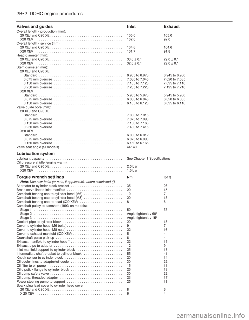
Valves and guidesInletExhaust
Overall length - production (mm):
20 XEJ and C20 XE . . . . . . . . . . . . . . . . . . . . . . . . . . . . . . . . . . . . . . .105.0105.0
X20 XEV . . . . . . . . . . . . . . . . . . . . . . . . . . . . . . . . . . . . . . . . . . . . . . .102.092.0
Overall length - service (mm):
20 XEJ and C20 XE . . . . . . . . . . . . . . . . . . . . . . . . . . . . . . . . . . . . . . .104.6104.6
X20 XEV . . . . . . . . . . . . . . . . . . . . . . . . . . . . . . . . . . . . . . . . . . . . . . .101.791.8
Head diameter (mm):
20 XEJ and C20 XE . . . . . . . . . . . . . . . . . . . . . . . . . . . . . . . . . . . . . . .33.0 ±0.129.0 ±0.1
X20 XEV . . . . . . . . . . . . . . . . . . . . . . . . . . . . . . . . . . . . . . . . . . . . . . .32.0 ±0.129.0 ±0.1
Stem diameter (mm):
20 XEJ and C20 XE
Standard . . . . . . . . . . . . . . . . . . . . . . . . . . . . . . . . . . . . . . . . . . . . .6.955 to 6.9706.945 to 6.960
0.075 mm oversize . . . . . . . . . . . . . . . . . . . . . . . . . . . . . . . . . . . . .7.030 to 7.0457.020 to 7.035
0.150 mm oversize . . . . . . . . . . . . . . . . . . . . . . . . . . . . . . . . . . . . .7.105 to 7.1207.095 to 7.110
0.250 mm oversize . . . . . . . . . . . . . . . . . . . . . . . . . . . . . . . . . . . . .7.205 to 7.2207.195 to 7.210
X20 XEV
Standard . . . . . . . . . . . . . . . . . . . . . . . . . . . . . . . . . . . . . . . . . . . . .5.955 to 5.9705.945 to 5.960
0.075 mm oversize . . . . . . . . . . . . . . . . . . . . . . . . . . . . . . . . . . . . .6.030 to 6.0456.020 to 6.035
0.150 mm oversize . . . . . . . . . . . . . . . . . . . . . . . . . . . . . . . . . . . . .6.105 to 6.1206.095 to 6.110
Valve guide bore (mm):
20 XEJ and C20 XE
Standard . . . . . . . . . . . . . . . . . . . . . . . . . . . . . . . . . . . . . . . . . . . . .7.000 to 7.015
0.075 mm oversize . . . . . . . . . . . . . . . . . . . . . . . . . . . . . . . . . . . . .7.075 to 7.090
0.150 mm oversize . . . . . . . . . . . . . . . . . . . . . . . . . . . . . . . . . . . . .7.150 to 7.165
0.250 mm oversize . . . . . . . . . . . . . . . . . . . . . . . . . . . . . . . . . . . . .7.400 to 7.415
X20 XEV
Standard . . . . . . . . . . . . . . . . . . . . . . . . . . . . . . . . . . . . . . . . . . . . .6.000 to 6.012
0.075 mm oversize . . . . . . . . . . . . . . . . . . . . . . . . . . . . . . . . . . . . .6.075 to 6.090
0.150 mm oversize . . . . . . . . . . . . . . . . . . . . . . . . . . . . . . . . . . . . .6.150 to 6.165
Valve seat angle (all models) . . . . . . . . . . . . . . . . . . . . . . . . . . . . . . . . .44°40’
Lubrication system
Lubricant capacity . . . . . . . . . . . . . . . . . . . . . . . . . . . . . . . . . . . . . . . . .See Chapter 1 Specifications
Oil pressure at idle (engine warm):
20 XEJ and C20 XE . . . . . . . . . . . . . . . . . . . . . . . . . . . . . . . . . . . . . . .2.5 bar
X20 XEV . . . . . . . . . . . . . . . . . . . . . . . . . . . . . . . . . . . . . . . . . . . . . . .1.5 bar
Torque wrench settingsNmlbf ft
Note: Use new bolts (or nuts, if applicable), where asterisked (*).
Alternator to cylinder block bracket . . . . . . . . . . . . . . . . . . . . . . . . . . . .3526
Brake servo line to inlet manifold . . . . . . . . . . . . . . . . . . . . . . . . . . . . . .2015
Camshaft bearing cap to cylinder head (M6) . . . . . . . . . . . . . . . . . . . . .107
Camshaft bearing cap to cylinder head (M8) . . . . . . . . . . . . . . . . . . . . .2015
Camshaft bearing cap to head (X20 XEV) . . . . . . . . . . . . . . . . . . . . . . .86
Camshaft pulley to camshaft (1993-on models):
Stage 1 . . . . . . . . . . . . . . . . . . . . . . . . . . . . . . . . . . . . . . . . . . . . . . . .5037
Stage 2 . . . . . . . . . . . . . . . . . . . . . . . . . . . . . . . . . . . . . . . . . . . . . . . .Angle tighten by 60°
Stage 3 . . . . . . . . . . . . . . . . . . . . . . . . . . . . . . . . . . . . . . . . . . . . . . . .Angle tighten by 15°
Coolant pipe to cylinder block . . . . . . . . . . . . . . . . . . . . . . . . . . . . . . . .2015
Cover to cylinder head (M6 bolts) . . . . . . . . . . . . . . . . . . . . . . . . . . . . . .97
Cover to cylinder head (M8 nuts) . . . . . . . . . . . . . . . . . . . . . . . . . . . . . .2216
Cover to exhaust manifold (X20 XEV) . . . . . . . . . . . . . . . . . . . . . . . . . . .54
Crankshaft pulse pick-up . . . . . . . . . . . . . . . . . . . . . . . . . . . . . . . . . . . .64
Exhaust manifold to cylinder head * . . . . . . . . . . . . . . . . . . . . . . . . . . . .2216
Exhaust pipe to adapter . . . . . . . . . . . . . . . . . . . . . . . . . . . . . . . . . . . . .129
Inlet manifold support to cylinder block . . . . . . . . . . . . . . . . . . . . . . . . .2518
Intermediate shaft bracket to cylinder block . . . . . . . . . . . . . . . . . . . . .5541
Knock sensor to cylinder block . . . . . . . . . . . . . . . . . . . . . . . . . . . . . . .2014
Oil cooler lines to adapter/oil cooler . . . . . . . . . . . . . . . . . . . . . . . . . . . .3022
Oil filter to oil pump . . . . . . . . . . . . . . . . . . . . . . . . . . . . . . . . . . . . . . . .1511
Oil dipstick flange to cylinder block . . . . . . . . . . . . . . . . . . . . . . . . . . . .2518
Oil pump safety valve . . . . . . . . . . . . . . . . . . . . . . . . . . . . . . . . . . . . . . .3022
Oil pump, threaded adapter . . . . . . . . . . . . . . . . . . . . . . . . . . . . . . . . . .2317
Power steering pump to support . . . . . . . . . . . . . . . . . . . . . . . . . . . . . .2518
Spark plug lead cover to cylinder head cover:
20 XEJ and C20 XE . . . . . . . . . . . . . . . . . . . . . . . . . . . . . . . . . . . . . . .86
X 20 XEV . . . . . . . . . . . . . . . . . . . . . . . . . . . . . . . . . . . . . . . . . . . . . . .64
2B•2DOHC engine procedures
Page 190 of 525
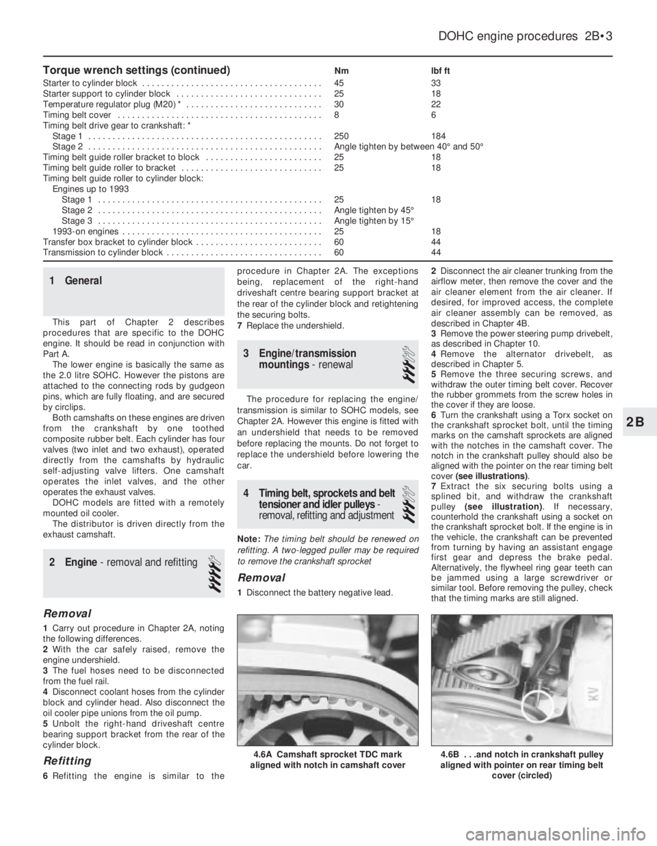
Torque wrench settings (continued)Nmlbf ft
Starter to cylinder block . . . . . . . . . . . . . . . . . . . . . . . . . . . . . . . . . . . . .4533
Starter support to cylinder block . . . . . . . . . . . . . . . . . . . . . . . . . . . . . .2518
Temperature regulator plug (M20) * . . . . . . . . . . . . . . . . . . . . . . . . . . . .3022
Timing belt cover . . . . . . . . . . . . . . . . . . . . . . . . . . . . . . . . . . . . . . . . . .86
Timing belt drive gear to crankshaft: *
Stage 1 . . . . . . . . . . . . . . . . . . . . . . . . . . . . . . . . . . . . . . . . . . . . . . . .250184
Stage 2 . . . . . . . . . . . . . . . . . . . . . . . . . . . . . . . . . . . . . . . . . . . . . . . .Angle tighten by between 40°and 50°
Timing belt guide roller bracket to block . . . . . . . . . . . . . . . . . . . . . . . .2518
Timing belt guide roller to bracket . . . . . . . . . . . . . . . . . . . . . . . . . . . . .2518
Timing belt guide roller to cylinder block:
Engines up to 1993
Stage 1 . . . . . . . . . . . . . . . . . . . . . . . . . . . . . . . . . . . . . . . . . . . . . .2518
Stage 2 . . . . . . . . . . . . . . . . . . . . . . . . . . . . . . . . . . . . . . . . . . . . . .Angle tighten by 45°
Stage 3 . . . . . . . . . . . . . . . . . . . . . . . . . . . . . . . . . . . . . . . . . . . . . .Angle tighten by 15°
1993-on engines . . . . . . . . . . . . . . . . . . . . . . . . . . . . . . . . . . . . . . . . .2518
Transfer box bracket to cylinder block . . . . . . . . . . . . . . . . . . . . . . . . . .6044
Transmission to cylinder block . . . . . . . . . . . . . . . . . . . . . . . . . . . . . . . .6044
1General
This part of Chapter 2 describes
procedures that are specific to the DOHC
engine. It should be read in conjunction with
Part A.
The lower engine is basically the same as
the 2.0 litre SOHC. However the pistons are
attached to the connecting rods by gudgeon
pins, which are fully floating, and are secured
by circlips.
Both camshafts on these engines are driven
from the crankshaft by one toothed
composite rubber belt. Each cylinder has four
valves (two inlet and two exhaust), operated
directly from the camshafts by hydraulic
self-adjusting valve lifters. One camshaft
operates the inlet valves, and the other
operates the exhaust valves.
DOHC models are fitted with a remotely
mounted oil cooler.
The distributor is driven directly from the
exhaust camshaft.
2Engine - removal and refitting
4
Removal
1Carry out procedure in Chapter 2A, noting
the following differences.
2With the car safely raised, remove the
engine undershield.
3The fuel hoses need to be disconnected
from the fuel rail.
4Disconnect coolant hoses from the cylinder
block and cylinder head. Also disconnect the
oil cooler pipe unions from the oil pump.
5Unbolt the right-hand driveshaft centre
bearing support bracket from the rear of the
cylinder block.
Refitting
6Refitting the engine is similar to theprocedure in Chapter 2A. The exceptions
being, replacement of the right-hand
driveshaft centre bearing support bracket at
the rear of the cylinder block and retightening
the securing bolts.
7Replace the undershield.
3Engine/transmission
mountings- renewal
3
The procedure for replacing the engine/
transmission is similar to SOHC models, see
Chapter 2A. However this engine is fitted with
an undershield that needs to be removed
before replacing the mounts. Do not forget to
replace the undershield before lowering the
car.
4Timing belt, sprockets and belt
tensioner and idler pulleys-
removal, refitting and adjustment
3
Note: The timing belt should be renewed on
refitting. A two-legged puller may be required
to remove the crankshaft sprocket
Removal
1Disconnect the battery negative lead.2Disconnect the air cleaner trunking from the
airflow meter, then remove the cover and the
air cleaner element from the air cleaner. If
desired, for improved access, the complete
air cleaner assembly can be removed, as
described in Chapter 4B.
3Remove the power steering pump drivebelt,
as described in Chapter 10.
4Remove the alternator drivebelt, as
described in Chapter 5.
5Remove the three securing screws, and
withdraw the outer timing belt cover. Recover
the rubber grommets from the screw holes in
the cover if they are loose.
6Turn the crankshaft using a Torx socket on
the crankshaft sprocket bolt, until the timing
marks on the camshaft sprockets are aligned
with the notches in the camshaft cover. The
notch in the crankshaft pulley should also be
aligned with the pointer on the rear timing belt
cover (see illustrations).
7Extract the six securing bolts using a
splined bit, and withdraw the crankshaft
pulley (see illustration). If necessary,
counterhold the crankshaft using a socket on
the crankshaft sprocket bolt. If the engine is in
the vehicle, the crankshaft can be prevented
from turning by having an assistant engage
first gear and depress the brake pedal.
Alternatively, the flywheel ring gear teeth can
be jammed using a large screwdriver or
similar tool. Before removing the pulley, check
that the timing marks are still aligned.
DOHC engine procedures 2B•3
4.6B . . .and notch in crankshaft pulley
aligned with pointer on rear timing belt
cover (circled)4.6A Camshaft sprocket TDC mark
aligned with notch in camshaft cover
2B
Page 192 of 525
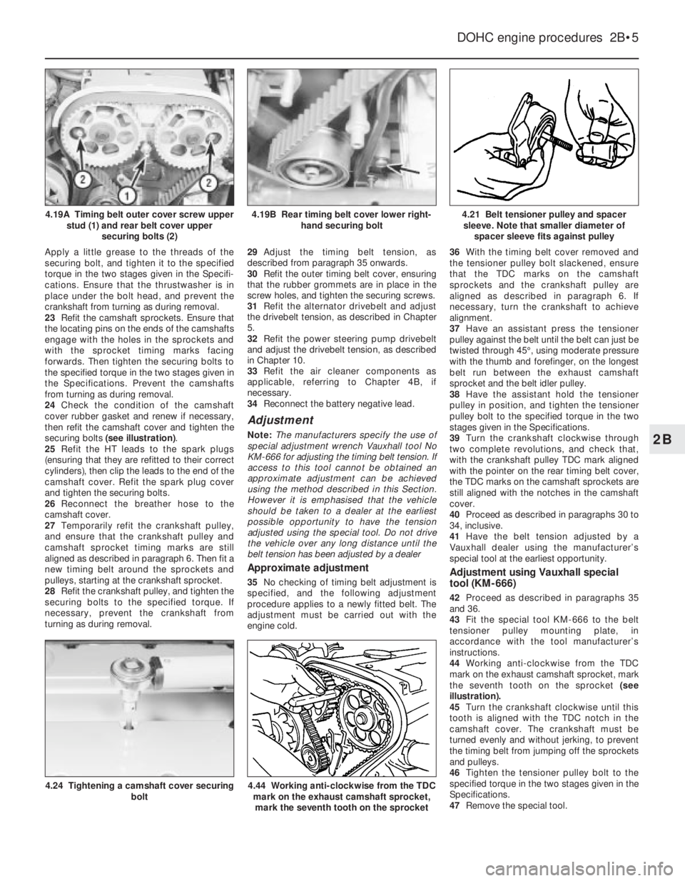
Apply a little grease to the threads of the
securing bolt, and tighten it to the specified
torque in the two stages given in the Specifi-
cations. Ensure that the thrustwasher is in
place under the bolt head, and prevent the
crankshaft from turning as during removal.
23Refit the camshaft sprockets. Ensure that
the locating pins on the ends of the camshafts
engage with the holes in the sprockets and
with the sprocket timing marks facing
forwards. Then tighten the securing bolts to
the specified torque in the two stages given in
the Specifications. Prevent the camshafts
from turning as during removal.
24Check the condition of the camshaft
cover rubber gasket and renew if necessary,
then refit the camshaft cover and tighten the
securing bolts (see illustration).
25Refit the HT leads to the spark plugs
(ensuring that they are refitted to their correct
cylinders), then clip the leads to the end of the
camshaft cover. Refit the spark plug cover
and tighten the securing bolts.
26Reconnect the breather hose to the
camshaft cover.
27Temporarily refit the crankshaft pulley,
and ensure that the crankshaft pulley and
camshaft sprocket timing marks are still
aligned as described in paragraph 6. Then fit a
new timing belt around the sprockets and
pulleys, starting at the crankshaft sprocket.
28Refit the crankshaft pulley, and tighten the
securing bolts to the specified torque. If
necessary, prevent the crankshaft from
turning as during removal. 29Adjust the timing belt tension, as
described from paragraph 35 onwards.
30Refit the outer timing belt cover, ensuring
that the rubber grommets are in place in the
screw holes, and tighten the securing screws.
31Refit the alternator drivebelt and adjust
the drivebelt tension, as described in Chapter
5.
32Refit the power steering pump drivebelt
and adjust the drivebelt tension, as described
in Chapter 10.
33Refit the air cleaner components as
applicable, referring to Chapter 4B, if
necessary.
34Reconnect the battery negative lead.
Adjustment
Note: The manufacturers specify the use of
special adjustment wrench Vauxhall tool No
KM-666 for adjusting the timing belt tension. If
access to this tool cannot be obtained an
approximate adjustment can be achieved
using the method described in this Section.
However it is emphasised that the vehicle
should be taken to a dealer at the earliest
possible opportunity to have the tension
adjusted using the special tool. Do not drive
the vehicle over any long distance until the
belt tension has been adjusted by a dealer
Approximate adjustment
35No checking of timing belt adjustment is
specified, and the following adjustment
procedure applies to a newly fitted belt. The
adjustment must be carried out with the
engine cold.36With the timing belt cover removed and
the tensioner pulley bolt slackened, ensure
that the TDC marks on the camshaft
sprockets and the crankshaft pulley are
aligned as described in paragraph 6. If
necessary, turn the crankshaft to achieve
alignment.
37Have an assistant press the tensioner
pulley against the belt until the belt can just be
twisted through 45°, using moderate pressure
with the thumb and forefinger, on the longest
belt run between the exhaust camshaft
sprocket and the belt idler pulley.
38Have the assistant hold the tensioner
pulley in position, and tighten the tensioner
pulley bolt to the specified torque in the two
stages given in the Specifications.
39Turn the crankshaft clockwise through
two complete revolutions, and check that,
with the crankshaft pulley TDC mark aligned
with the pointer on the rear timing belt cover,
the TDC marks on the camshaft sprockets are
still aligned with the notches in the camshaft
cover.
40Proceed as described in paragraphs 30 to
34, inclusive.
41Have the belt tension adjusted by a
Vauxhall dealer using the manufacturer’s
special tool at the earliest opportunity.Adjustment using Vauxhall special
tool (KM-666)
42Proceed as described in paragraphs 35
and 36.
43Fit the special tool KM-666 to the belt
tensioner pulley mounting plate, in
accordance with the tool manufacturer’s
instructions.
44Working anti-clockwise from the TDC
mark on the exhaust camshaft sprocket, mark
the seventh tooth on the sprocket (see
illustration).
45Turn the crankshaft clockwise until this
tooth is aligned with the TDC notch in the
camshaft cover. The crankshaft must be
turned evenly and without jerking, to prevent
the timing belt from jumping off the sprockets
and pulleys.
46Tighten the tensioner pulley bolt to the
specified torque in the two stages given in the
Specifications.
47Remove the special tool.
DOHC engine procedures 2B•5
4.21 Belt tensioner pulley and spacer
sleeve. Note that smaller diameter of
spacer sleeve fits against pulley
4.44 Working anti-clockwise from the TDC
mark on the exhaust camshaft sprocket,
mark the seventh tooth on the sprocket4.24 Tightening a camshaft cover securing
bolt
4.19B Rear timing belt cover lower right-
hand securing bolt4.19A Timing belt outer cover screw upper
stud (1) and rear belt cover upper
securing bolts (2)
2B
Page 193 of 525
48Turn the crankshaft clockwise until the
TDC marks on the camshaft sprockets are
aligned with the notches in the camshaft
cover, and check that the crankshaft pulley
TDC mark is aligned with the pointer on the
rear timing belt cover.
49Proceed as described in paragraphs 30 to
34 inclusive.
5Timing belt, with automatic
adjuster- removal, refitting
and adjustment
3
Removal
1The operations are essentially the same as
described in Section 4, except that the
tensioner pulley incorporates an automatic
adjuster that simplifies the procedure as
follows.
2To release the belt tension before removal,
unscrew the timing belt tensioner pulley
securing bolt slightly then, with a large
screwdriver (or similar tool) inserted in the slot
on the tensioner arm, turn the tensioner arm
until the timing belt is slack. Tighten the
securing bolt slightly to hold the tensioner in
this position.
Refitting
3To refit the timing belt, first ensure that the
coolant pump is correctly positioned by
checking that the lug on the coolant pump
flange is aligned with the corresponding lug
on the cylinder block. If this is not the case,
slacken the coolant pump mounting bolts
slightly and move the pump accordingly.
Tighten the bolts to the specified torque on
completion (see Chapter 3).
4Refit the timing belt as described in Section 4,
then tension it as follows.
Adjustment
5Slacken the tensioner pulley securing bolt
and move the tensioner arm anti-clockwise,
until the tensioner pointer lies at its stop.
Tighten the tensioner pulley securing bolt to
hold the tensioner in this position.
6Turn the crankshaft through two complete
revolutions in the normal direction of rotation
and check that with the crankshaft pulley TDC
mark aligned with the pointer on the rear
timing belt cover, the TDC marks on the
camshaft sprockets are still aligned with the
notches in the camshaft cover.
7Slacken the tensioner pulley securing bolt
once again and move the tensioner arm
clockwise, until the tensioner pointer is
aligned with the notch in the tensioner. In the
first few hours of operation a new belt will be
subjected to ‘settling-in’, (known as the
running-in procedure). If you are refitting a
used belt (one that has been ‘run-in’), align the
pointer to approximately 4 mm to the left of
the notch, refer to Section 14 in Chapter 2A.
Tighten the tensioner pulley securing bolt
securely. Turn the crankshaft through onecomplete revolution in the normal direction of
rotation and check that the crankshaft and
camshaft timing marks still align, then refit the
remainder of the components as described in
Section 4.
8With the timing belt adjustment set in this
way, correct tension will always be maintained
by the automatic tensioner and no further
checking or adjustment will be necessary.
6Camshaft front oil seal-
removal and refitting
3
Note: A new timing belt should be used on
refitting
Removal
1The camshaft front oil seals may be
renewed with the engine in the vehicle without
removing the camshafts as follows.
2Remove the timing belt and the relevant
camshaft sprocket(s), as described in Section 4.
3Punch or drill a small hole in the centre of
the now-exposed oil seal. Screw in a
self-tapping screw, and pull on the screw with
pliers to extract the seal.
4Clean the oil seal seat with a wooden or
plastic scraper.
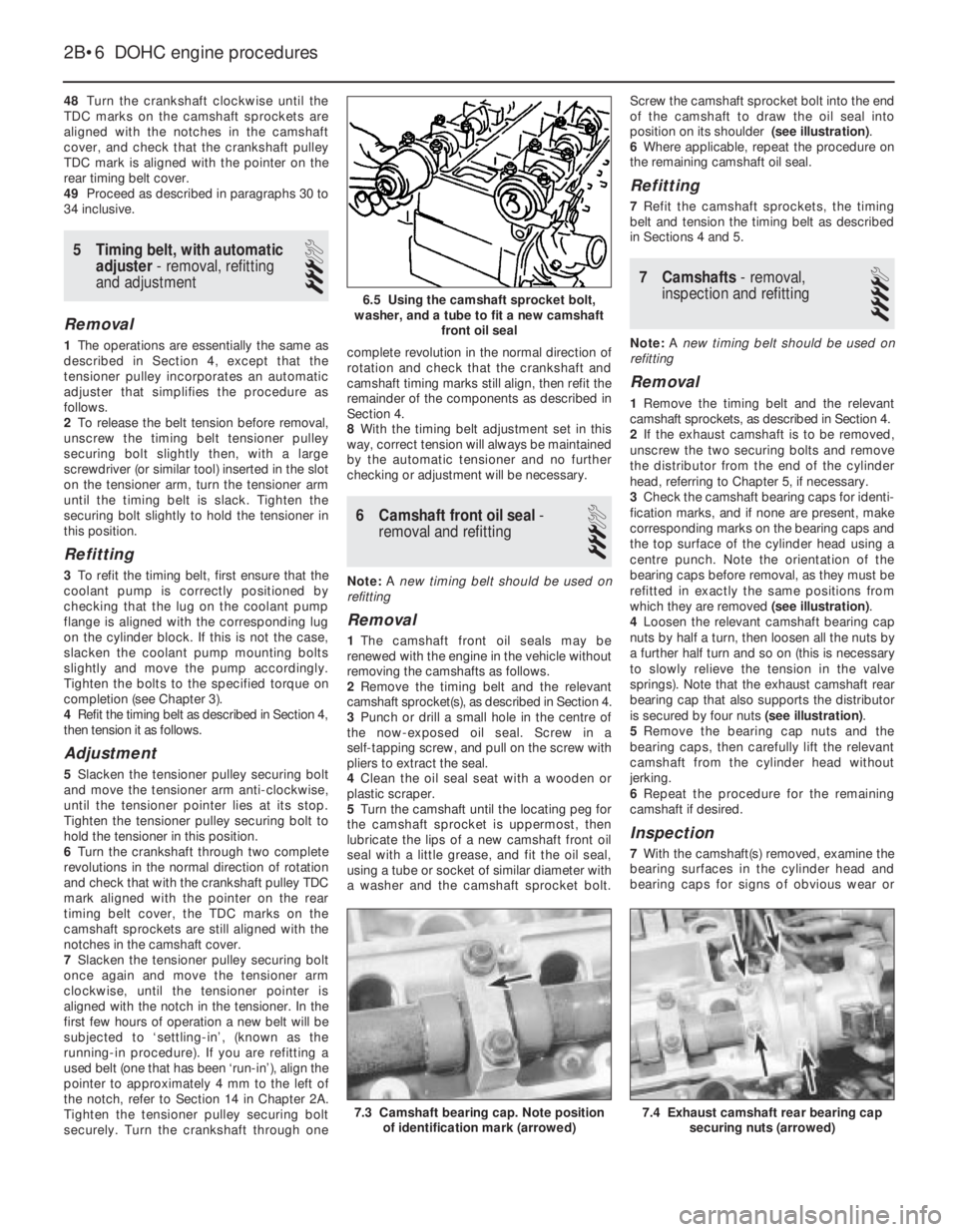
5Turn the camshaft until the locating peg for
the camshaft sprocket is uppermost, then
lubricate the lips of a new camshaft front oil
seal with a little grease, and fit the oil seal,
using a tube or socket of similar diameter with
a washer and the camshaft sprocket bolt.Screw the camshaft sprocket bolt into the end
of the camshaft to draw the oil seal into
position on its shoulder (see illustration).
6Where applicable, repeat the procedure on
the remaining camshaft oil seal.
Refitting
7Refit the camshaft sprockets, the timing
belt and tension the timing belt as described
in Sections 4 and 5.
7Camshafts- removal,
inspection and refitting
4
Note: A new timing belt should be used on
refitting
Removal
1Remove the timing belt and the relevant
camshaft sprockets, as described in Section 4.
2If the exhaust camshaft is to be removed,
unscrew the two securing bolts and remove
the distributor from the end of the cylinder
head, referring to Chapter 5, if necessary.
3Check the camshaft bearing caps for identi-
fication marks, and if none are present, make
corresponding marks on the bearing caps and
the top surface of the cylinder head using a
centre punch. Note the orientation of the
bearing caps before removal, as they must be
refitted in exactly the same positions from
which they are removed (see illustration).
4Loosen the relevant camshaft bearing cap
nuts by half a turn, then loosen all the nuts by
a further half turn and so on (this is necessary
to slowly relieve the tension in the valve
springs). Note that the exhaust camshaft rear
bearing cap that also supports the distributor
is secured by four nuts (see illustration).
5Remove the bearing cap nuts and the
bearing caps, then carefully lift the relevant
camshaft from the cylinder head without
jerking.
6Repeat the procedure for the remaining
camshaft if desired.
Inspection
7With the camshaft(s) removed, examine the
bearing surfaces in the cylinder head and
bearing caps for signs of obvious wear or
2B•6DOHC engine procedures
6.5 Using the camshaft sprocket bolt,
washer, and a tube to fit a new camshaft
front oil seal
7.4 Exhaust camshaft rear bearing cap
securing nuts (arrowed)7.3 Camshaft bearing cap. Note position
of identification mark (arrowed)
Page 194 of 525
pitting. If evident, the cylinder head and all
bearing caps must be renewed as a matched
set, as there is no provision for refacing if the
bearing caps cannot be renewed individually.
8The camshaft(s) should show no marks or
scoring on the journal or cam lobe surfaces. if
evident, renew the camshaft(s).
9It is advisable to renew the camshaft front
oil seal(s) as a matter of course. Prise the old
seal(s) from the front of the camshaft(s) and
discard them.
Refitting
10Begin refitting by liberally coating the
contact faces of the hydraulic valve lifters and
the camshaft(s) with molybdenum disulphide
paste.
11Coat the mating faces of the front and
rear bearing caps with sealing compound and
refit the bearing caps in their original positions
as noted during removal.
12Tighten the camshaft bearing cap nuts to
the specified torque in half-turn stages, as
when loosening the nuts. Note that when
refitting the exhaust camshaft, the two smaller
rear bearing cap securing nuts should be
tightened after all the main camshaft bearing
cap nuts have been tightened. Note also that
the two smaller nuts should be tightened to a
lower torque wrench setting than the main
nuts.
13Turn the camshaft until the locating peg
for the camshaft sprocket is uppermost, then
lubricate the lips of a rear camshaft front oil
seal with a little grease, and fit the oil seal,
using a tube or socket of similar diameter with
a washer and the camshaft sprocket bolt.
Screw the camshaft sprocket bolt into the end
of the camshaft to draw the oil seal into
position on its shoulder.
14Repeat the procedure for the remaining
camshaft.
15Refit the distributor with reference to
Chapter 5. Fit a new timing belt and the
camshaft sprockets, then adjust the timing
belt as described in Section 4 or 5, as
applicable.
8Cylinder head -removal and
refitting (engine in vehicle)
4
Note: The engine must be cold when the
cylinder head is removed. Do not remove the
cylinder head from a hot engine. New cylinder
head bolts, a new cylinder head gasket and a
new timing belt must be used on refitting.
The torque settings (as shown in Chapter 2A)
are only applicable to latest specification head
bolts, available from Vauxhall. Earlier type or
alternative make, head bolts may require
different torques. Consult your supplier
Removal
1Disconnect the battery negative lead.
2Drain the cooling system, as described in
Chapter 3.3Remove the front section of the exhaust
system, as described in Chapter 4C.
4The cylinder head can be removed
complete with the inlet manifold, or the inlet
manifold can be detached from the cylinder
head before removal, with reference to
Chapter 4B. If no work is to be carried out on
the inlet manifold, it can be unbolted from the
cylinder head and supported to one side out
of the way, thus avoiding the need to
disconnect the relevant hoses, pipes and
wiring.
5If the cylinder head is to be removed
complete with the inlet manifold, disconnect
all relevant hoses, pipes and wiring from the
inlet manifold and associated components,
referring to Chapter 4B, and unbolt the
manifold support bracket from the manifold.
Loosen the alternator mountings with
reference to Chapter 5, then unbolt the upper
alternator mounting from the inlet manifold.
6If the inlet manifold is to be left in the engine
compartment, continue as follows, otherwise
go on to paragraph 17.
7Disconnect the wiring plug from the airflow
meter, and the breather hose from the air box
on the throttle body. Disconnect the air
cleaner trunking and remove the airflow
meter/air box assembly from the throttle
body. Refer to Chapter 4B if necessary.
8Disconnect the end of the throttle cable
from the throttle valve lever, then unbolt the
throttle cable support bracket and remove it
from the inlet manifold.
9Unscrew the two earth lead securing nuts
from the fuel rail (one at each end of the rail)
and disconnect the three earth leads.
10Disconnect the wiring plug from the
throttle position switch.
11Pull up on the wiring harness housing, and
disconnect the wiring plugs from the fuel
injectors by compressing the retaining clips.
Move the wiring harness housing to one side.
12Disconnect the two breather hoses from
the rear of the camshaft cover.
13Loosen the alternator mountings, with
reference to Chapter 5, then unbolt the upper
alternator mounting from the inlet manifold.
14Unbolt the manifold support bracket from
the manifold.15Make a final check to ensure that all
necessary hoses, pipes and wires have been
disconnected, then unscrew the securing nuts
and lift the inlet manifold from the cylinder
head. Ensure that the manifold is properly
supported, taking care not to strain any of the
hoses, pipes and wires, etc., which are still
connected.
16Recover the manifold gasket from the
cylinder head.
17Remove the timing belt, camshaft
sprockets, and timing belt tensioner and idler
pulleys, as described in Section 4.
18Unscrew the upper and middle studs for
the timing belt outer cover screws. Note that
the upper stud simply unscrews from the
cylinder head, but the middle stud is secured
by a bolt.
19Unscrew the two upper rear timing belt
cover securing bolts from the cylinder head.
20Remove the distributor cap and HT leads
with reference to Chapter 5.
21Disconnect the distributor wiring plug.
22Disconnect the coolant hose from the
left-hand end of the cylinder head.
23Unscrew the bolt securing the crankcase
breather tube bracket to the end of the
cylinder head.
24Disconnect the radiator top hose from the
thermostat housing, and disconnect the
wiring plugs from the temperature gauge
sender and the coolant temperature sensor
(both situated in the thermostat housing).
25Make a final check to ensure that all
relevant hoses, pipes and wires have been
disconnected.
26On X20 XEV models, remove the
camshaft, as described in Section 7.
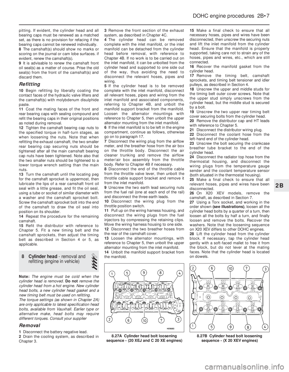
27Using a Torx socket, and working in the
order shown (see illustrations), loosen all the
cylinder head bolts by a quarter of a turn, then
loosen all the bolts by half a turn, and finally
loosen and remove the bolts. Recover the
washers. Note that the loosening sequence
on X20 XEV differs to other DOHC engines.
28Lift the cylinder head from the cylinder
block. If necessary, tap the cylinder head
gently with a soft-faced mallet to free it from
the block, but do not lever at the mating
faces. Note that the cylinder head is located
on dowels.
DOHC engine procedures 2B•7
8.27B Cylinder head bolt loosening
sequence - (X 20 XEV engines)8.27A Cylinder head bolt loosening
sequence - (20 XEJ and C 20 XE engines)
2B
Page 195 of 525
29Recover the cylinder head gasket and
discard it.
30Clean the cylinder head and block mating
faces by careful scraping. Take care not to
damage the cylinder head, which is made of
light alloy and is easily scored. Cover the
coolant passages and other openings with
masking tape or rag, to prevent dirt and
carbon falling in. Mop out all the oil from the
bolt holes; if oil is left in the holes, hydraulic
pressure could crack the block when the bolts
are refitted.
31If desired, the cylinder head can be
dismantled and inspected as described in
Section 10.
Refitting
32Begin refitting by locating a new gasket
on the block so that the word “OBEN” or
“TOP” is uppermost at the timing belt end of
the engine.
33With the mating faces scrupulously clean,
locate the cylinder head on the block so that
the positioning dowels engage in their holes.
34Temporarily refit the crankshaft pulley and
the camshaft sprockets, and ensure that the
timing marks are still positioned as they were
before the timing belt was removed (see
Section 4).35Fit the new cylinder head bolts, ensuring
that the washers are in place under their
heads, and screw the bolts in by hand as far
as possible.
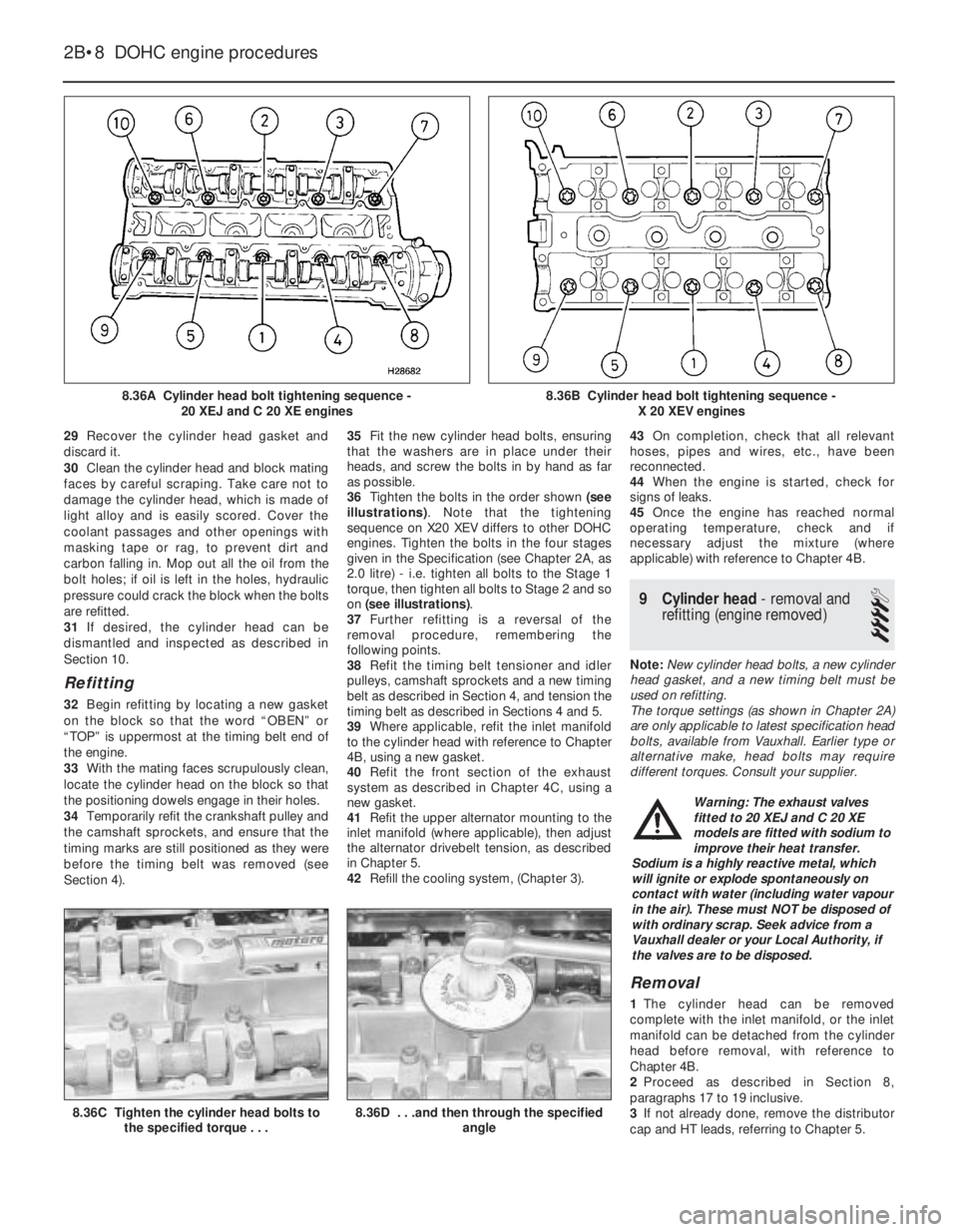
36Tighten the bolts in the order shown (see
illustrations). Note that the tightening
sequence on X20 XEV differs to other DOHC
engines. Tighten the bolts in the four stages
given in the Specification (see Chapter 2A, as
2.0 litre) - i.e. tighten all bolts to the Stage 1
torque, then tighten all bolts to Stage 2 and so
on (see illustrations).
37Further refitting is a reversal of the
removal procedure, remembering the
following points.
38Refit the timing belt tensioner and idler
pulleys, camshaft sprockets and a new timing
belt as described in Section 4, and tension the
timing belt as described in Sections 4 and 5.
39Where applicable, refit the inlet manifold
to the cylinder head with reference to Chapter
4B, using a new gasket.
40Refit the front section of the exhaust
system as described in Chapter 4C, using a
new gasket.
41Refit the upper alternator mounting to the
inlet manifold (where applicable), then adjust
the alternator drivebelt tension, as described
in Chapter 5.
42Refill the cooling system, (Chapter 3).43On completion, check that all relevant
hoses, pipes and wires, etc., have been
reconnected.
44When the engine is started, check for
signs of leaks.
45Once the engine has reached normal
operating temperature, check and if
necessary adjust the mixture (where
applicable) with reference to Chapter 4B.
9Cylinder head -removal and
refitting (engine removed)
4
Note: New cylinder head bolts, a new cylinder
head gasket, and a new timing belt must be
used on refitting.
The torque settings (as shown in Chapter 2A)
are only applicable to latest specification head
bolts, available from Vauxhall. Earlier type or
alternative make, head bolts may require
different torques. Consult your supplier.
Removal
1The cylinder head can be removed
complete with the inlet manifold, or the inlet
manifold can be detached from the cylinder
head before removal, with reference to
Chapter 4B.
2Proceed as described in Section 8,
paragraphs 17 to 19 inclusive.
3If not already done, remove the distributor
cap and HT leads, referring to Chapter 5.
2B•8DOHC engine procedures
8.36A Cylinder head bolt tightening sequence -
20 XEJ and C 20 XE engines
8.36C Tighten the cylinder head bolts to
the specified torque . . .8.36D . . .and then through the specified
angle
8.36B Cylinder head bolt tightening sequence -
X 20 XEV engines
Warning: The exhaust valves
fitted to 20 XEJ and C 20 XE
models are fitted with sodium to
improve their heat transfer.
Sodium is a highly reactive metal, which
will ignite or explode spontaneously on
contact with water (including water vapour
in the air). These must NOT be disposed of
with ordinary scrap. Seek advice from a
Vauxhall dealer or your Local Authority, if
the valves are to be disposed.