fuel pressure OPEL CALIBRA 1988 Service Service Manual
[x] Cancel search | Manufacturer: OPEL, Model Year: 1988, Model line: CALIBRA, Model: OPEL CALIBRA 1988Pages: 525, PDF Size: 58.26 MB
Page 250 of 525

MOTTest Checks REF•11
MExamine the handbrake mechanism,
checking for frayed or broken cables,
excessive corrosion, or wear or insecurity of
the linkage. Check that the mechanism works
on each relevant wheel, and releases fully,
without binding.
MIt is not possible to test brake efficiency
without special equipment, but a road test can
be carried out later to check that the vehicle
pulls up in a straight line.
Fuel and exhaust systems
MInspect the fuel tank (including the filler
cap), fuel pipes, hoses and unions. All
components must be secure and free from
leaks.
MExamine the exhaust system over its entire
length, checking for any damaged, broken or
missing mountings, security of the retaining
clamps and rust or corrosion.
Wheels and tyres
MExamine the sidewalls and tread area of
each tyre in turn. Check for cuts, tears, lumps,
bulges, separation of the tread, and exposure
of the ply or cord due to wear or damage.
Check that the tyre bead is correctly seated
on the wheel rim, that the valve is sound andproperly seated, and that the wheel is not
distorted or damaged.
MCheck that the tyres are of the correct size
for the vehicle, that they are of the same size
and type on each axle, and that the pressures
are correct.
MCheck the tyre tread depth. The legal
minimum at the time of writing is 1.6 mm over
at least three-quarters of the tread width.
Abnormal tread wear may indicate incorrect
front wheel alignment.
Body corrosion
MCheck the condition of the entire vehicle
structure for signs of corrosion in load-bearing
areas. (These include chassis box sections,
side sills, cross-members, pillars, and all
suspension, steering, braking system and
seat belt mountings and anchorages.) Any
corrosion which has seriously reduced the
thickness of a load-bearing area is likely to
cause the vehicle to fail. In this case
professional repairs are likely to be needed.
MDamage or corrosion which causes sharp
or otherwise dangerous edges to be exposed
will also cause the vehicle to fail.
Petrol models
MHave the engine at normal operating
temperature, and make sure that it is in good
tune (ignition system in good order, air filter
element clean, etc).
MBefore any measurements are carried out,
raise the engine speed to around 2500 rpm,
and hold it at this speed for 20 seconds. Allowthe engine speed to return to idle, and watch
for smoke emissions from the exhaust
tailpipe. If the idle speed is obviously much
too high, or if dense blue or clearly-visible
black smoke comes from the tailpipe for more
than 5 seconds, the vehicle will fail. As a rule
of thumb, blue smoke signifies oil being burnt
(engine wear) while black smoke signifies
unburnt fuel (dirty air cleaner element, or other
carburettor or fuel system fault).
MAn exhaust gas analyser capable of
measuring carbon monoxide (CO) and
hydrocarbons (HC) is now needed. If such an
instrument cannot be hired or borrowed, a
local garage may agree to perform the check
for a small fee.
CO emissions (mixture)
MAt the time of writing, the maximum CO
level at idle is 3.5% for vehicles first used after
August 1986 and 4.5% for older vehicles.
From January 1996 a much tighter limit
(around 0.5%) applies to catalyst-equipped
vehicles first used from August 1992. If the
CO level cannot be reduced far enough to
pass the test (and the fuel and ignition
systems are otherwise in good condition) then
the carburettor is badly worn, or there is some
problem in the fuel injection system or
catalytic converter (as applicable).
HC emissionsMWith the CO emissions within limits, HC
emissions must be no more than 1200 ppm
(parts per million). If the vehicle fails this test
at idle, it can be re-tested at around 2000 rpm;
if the HC level is then 1200 ppm or less, this
counts as a pass.
MExcessive HC emissions can be caused by
oil being burnt, but they are more likely to be
due to unburnt fuel.
Diesel models
MThe only emission test applicable to Diesel
engines is the measuring of exhaust smoke
density. The test involves accelerating the
engine several times to its maximum
unloaded speed.
Note: It is of the utmost importance that the
engine timing belt is in good condition before
the test is carried out.
M
Excessive smoke can be caused by a dirty
air cleaner element. Otherwise, professional
advice may be needed to find the cause.
4Checks carried out on
YOUR VEHICLE’S EXHAUST
EMISSION SYSTEM
REF
Page 251 of 525
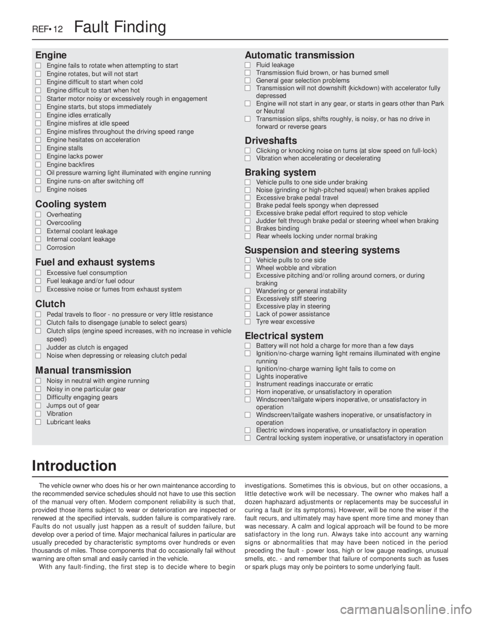
Engine
m mEngine fails to rotate when attempting to start
m mEngine rotates, but will not start
m mEngine difficult to start when cold
m mEngine difficult to start when hot
m mStarter motor noisy or excessively rough in engagement
m mEngine starts, but stops immediately
m mEngine idles erratically
m mEngine misfires at idle speed
m mEngine misfires throughout the driving speed range
m mEngine hesitates on acceleration
m mEngine stalls
m mEngine lacks power
m mEngine backfires
m mOil pressure warning light illuminated with engine running
m mEngine runs-on after switching off
m mEngine noises
Cooling system
m
mOverheating
m mOvercooling
m mExternal coolant leakage
m mInternal coolant leakage
m mCorrosion
Fuel and exhaust systems
m
mExcessive fuel consumption
m mFuel leakage and/or fuel odour
m mExcessive noise or fumes from exhaust system
Clutch
m
mPedal travels to floor - no pressure or very little resistance
m mClutch fails to disengage (unable to select gears)
m mClutch slips (engine speed increases, with no increase in vehicle
speed)
m mJudder as clutch is engaged
m mNoise when depressing or releasing clutch pedal
Manual transmission
m
mNoisy in neutral with engine running
m mNoisy in one particular gear
m mDifficulty engaging gears
m mJumps out of gear
m mVibration
m mLubricant leaks
Automatic transmission
m
mFluid leakage
m mTransmission fluid brown, or has burned smell
m mGeneral gear selection problems
m mTransmission will not downshift (kickdown) with accelerator fully
depressed
m mEngine will not start in any gear, or starts in gears other than Park
or Neutral
m mTransmission slips, shifts roughly, is noisy, or has no drive in
forward or reverse gears
Driveshafts
m mClicking or knocking noise on turns (at slow speed on full-lock)
m mVibration when accelerating or decelerating
Braking system
m
mVehicle pulls to one side under braking
m mNoise (grinding or high-pitched squeal) when brakes applied
m mExcessive brake pedal travel
m mBrake pedal feels spongy when depressed
m mExcessive brake pedal effort required to stop vehicle
m mJudder felt through brake pedal or steering wheel when braking
m mBrakes binding
m mRear wheels locking under normal braking
Suspension and steering systems
m
mVehicle pulls to one side
m mWheel wobble and vibration
m mExcessive pitching and/or rolling around corners, or during
braking
m mWandering or general instability
m mExcessively stiff steering
m mExcessive play in steering
m mLack of power assistance
m mTyre wear excessive
Electrical system
m
mBattery will not hold a charge for more than a few days
m mIgnition/no-charge warning light remains illuminated with engine
running
m mIgnition/no-charge warning light fails to come on
m mLights inoperative
m mInstrument readings inaccurate or erratic
m mHorn inoperative, or unsatisfactory in operation
m mWindscreen/tailgate wipers inoperative, or unsatisfactory in
operation
m mWindscreen/tailgate washers inoperative, or unsatisfactory in
operation
m mElectric windows inoperative, or unsatisfactory in operation
m mCentral locking system inoperative, or unsatisfactory in operation
The vehicle owner who does his or her own maintenance according to
the recommended service schedules should not have to use this section
of the manual very often. Modern component reliability is such that,
provided those items subject to wear or deterioration are inspected or
renewed at the specified intervals, sudden failure is comparatively rare.
Faults do not usually just happen as a result of sudden failure, but
develop over a period of time. Major mechanical failures in particular are
usually preceded by characteristic symptoms over hundreds or even
thousands of miles. Those components that do occasionally fail without
warning are often small and easily carried in the vehicle.
With any fault-finding, the first step is to decide where to begininvestigations. Sometimes this is obvious, but on other occasions, a
little detective work will be necessary. The owner who makes half a
dozen haphazard adjustments or replacements may be successful in
curing a fault (or its symptoms). However, will be none the wiser if the
fault recurs, and ultimately may have spent more time and money than
was necessary. A calm and logical approach will be found to be more
satisfactory in the long run. Always take into account any warning
signs or abnormalities that may have been noticed in the period
preceding the fault - power loss, high or low gauge readings, unusual
smells, etc. - and remember that failure of components such as fuses
or spark plugs may only be pointers to some underlying fault.
REF•12Fault Finding
Introduction
Page 252 of 525
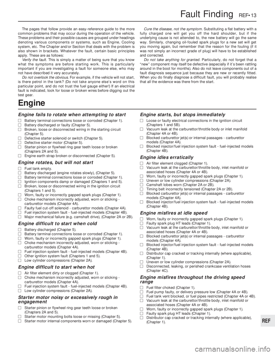
The pages that follow provide an easy-reference guide to the more
common problems that may occur during the operation of the vehicle.
These problems and their possible causes are grouped under headings
denoting various components or systems, such as Engine, Cooling
system, etc. The Chapter and/or Section that deals with the problem is
also shown in brackets. Whatever the fault, certain basic principles
apply. These are as follows:
Verify the fault. This is simply a matter of being sure that you know
what the symptoms are before starting work. This is particularly
important if you are investigating a fault for someone else, who may
not have described it very accurately.
Do not overlook the obvious. For example, if the vehicle will not start,
is there petrol in the tank? (Do not take anyone else’s word on this
particular point, and do not trust the fuel gauge either!) If an electrical
fault is indicated, look for loose or broken wires before digging out the
test gear.Cure the disease, not the symptom. Substituting a flat battery with a
fully charged one will get you off the hard shoulder, but if the
underlying cause is not attended to, the new battery will go the same
way. Similarly, changing oil-fouled spark plugs for a new set will get
you moving again, but remember that the reason for the fouling (if it
was not simply an incorrect grade of plug) will have to be established
and corrected.
Do not take anything for granted. Particularly, do not forget that a
“new” component may itself be defective (especially if it’s been rattling
around in the boot for months). Also do not leave components out of a
fault diagnosis sequence just because they are new or recently fitted.
When you do finally diagnose a difficult fault, you will probably realise
that all the evidence was there from the start.
Engine fails to rotate when attempting to start
MBattery terminal connections loose or corroded (Chapter 1).
MBattery discharged or faulty (Chapter 5).
MBroken, loose or disconnected wiring in the starting circuit
(Chapter 5).
MDefective starter solenoid or switch (Chapter 5).
MDefective starter motor (Chapter 5).
MStarter pinion or flywheel ring gear teeth loose or broken
(Chapters 2A and 5).
MEngine earth strap broken or disconnected (Chapter 5).
Engine rotates, but will not start
MFuel tank empty.
MBattery discharged (engine rotates slowly), (Chapter 5).
MBattery terminal connections loose or corroded (Chapter 1).
MIgnition components damp or damaged (Chapters 1 and 5).
MBroken, loose or disconnected wiring in the ignition circuit
(Chapters 1 and 5).
MWorn, faulty or incorrectly gapped spark plugs (Chapter 1).
MChoke mechanism incorrectly adjusted, worn or sticking -
carburettor models (Chapter 4A).
MFaulty fuel cut-off solenoid - carburettor models (Chapter 4A).
MFuel injection system fault - fuel-injected models (Chapter 4B).
MMajor mechanical failure (e.g. camshaft drive), (Chapter 2A or 2B).
Engine difficult to start when cold
MBattery discharged (Chapter 5).
MBattery terminal connections loose or corroded (Chapter 1).
MWorn, faulty or incorrectly gapped spark plugs (Chapter 1).
MChoke mechanism incorrectly adjusted, worn or sticking -
carburettor models (Chapter 4A).
MFuel injection system fault - fuel-injected models (Chapter 4B).
MOther ignition system fault (Chapters 1 and 5).
MLow cylinder compressions (Chapter 2A).
Engine difficult to start when hot
MAir filter element dirty or clogged (Chapter 1).
MChoke mechanism incorrectly adjusted, worn or sticking -
carburettor models (Chapter 4A).
MFuel injection system fault - fuel-injected models (Chapter 4B).
MLow cylinder compressions (Chapter 2A).
Starter motor noisy or excessively rough in
engagement
MStarter pinion or flywheel ring gear teeth loose or broken
(Chapters 2A and 5).
MStarter motor mounting bolts loose or missing (Chapter 5).
MStarter motor internal components worn or damaged (Chapter 5).
Engine starts, but stops immediately
MLoose or faulty electrical connections in the ignition circuit
(Chapters 1 and 5B).
MVacuum leak at the carburettor/throttle body or inlet manifold
(Chapter 4A or 4B).
MBlocked carburettor jet(s) or internal passages - carburettor
models (Chapter 4A).
MBlocked injector/fuel injection system fault - fuel-injected models
(Chapter 4B).
Engine idles erratically
MAir filter element clogged (Chapter 1).
MVacuum leak at the carburettor/throttle body, inlet manifold or
associated hoses (Chapter 4A or 4B).
MWorn, faulty or incorrectly gapped spark plugs (Chapter 1).
MUneven or low cylinder compressions (Chapter 2A).
MCamshaft lobes worn (Chapter 2A or 2B).
MTiming belt incorrectly tensioned (Chapter 2A or 2B).
MBlocked carburettor jet(s) or internal passages - carburettor
models (Chapter 4A).
MBlocked injector/fuel injection system fault - fuel-injected models
(Chapter 4B).
Engine misfires at idle speed
MWorn, faulty or incorrectly gapped spark plugs (Chapter 1).
MFaulty spark plug HT leads (Chapter 1).
MVacuum leak at the carburettor/throttle body, inlet manifold or
associated hoses (Chapter 4A or 4B).
MBlocked carburettor jet(s) or internal passages - carburettor
models (Chapter 4A).
MBlocked injector/fuel injection system fault - fuel-injected models
(Chapter 4B).
MDistributor cap cracked or tracking internally (where applicable),
(Chapter 1).
MUneven or low cylinder compressions (Chapter 2A).
MDisconnected, leaking, or perished crankcase ventilation hoses
(Chapter 4C).
Engine misfires throughout the driving speed
range
MFuel filter choked (Chapter 1).
MFuel pump faulty, or delivery pressure low (Chapter 4A or 4B).
MFuel tank vent blocked, or fuel pipes restricted (Chapter 4A or 4B).
MVacuum leak at the carburettor/throttle body, inlet manifold or
associated hoses (Chapter 4A or 4B).
MWorn, faulty or incorrectly gapped spark plugs (Chapter 1).
MFaulty spark plug HT leads (Chapter 1).
MDistributor cap cracked or tracking internally (where applicable),
(Chapter 1).
Fault Finding REF•13
REF
Engine
Page 253 of 525
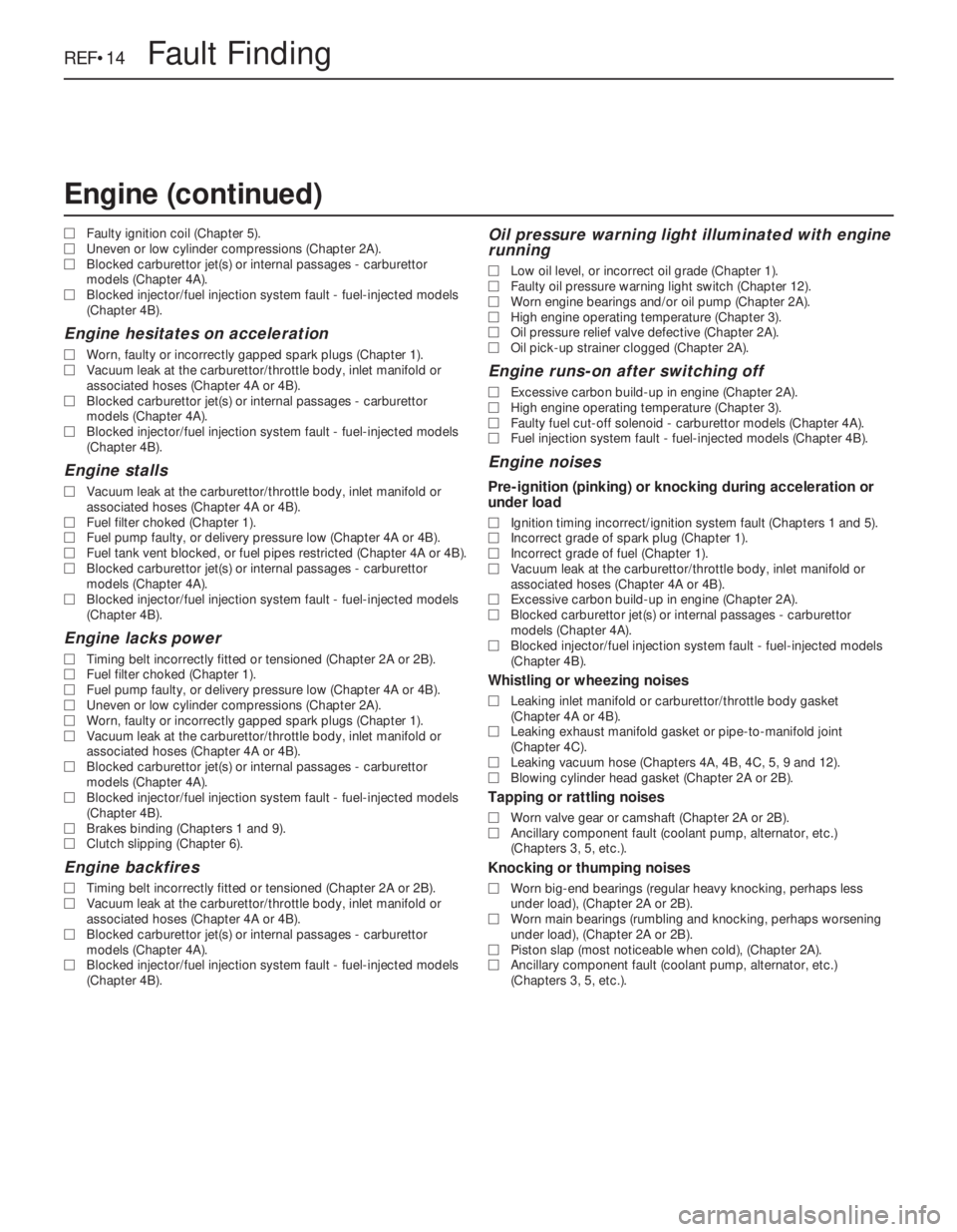
MFaulty ignition coil (Chapter 5).
MUneven or low cylinder compressions (Chapter 2A).
MBlocked carburettor jet(s) or internal passages - carburettor
models (Chapter 4A).
MBlocked injector/fuel injection system fault - fuel-injected models
(Chapter 4B).
Engine hesitates on acceleration
MWorn, faulty or incorrectly gapped spark plugs (Chapter 1).
MVacuum leak at the carburettor/throttle body, inlet manifold or
associated hoses (Chapter 4A or 4B).
MBlocked carburettor jet(s) or internal passages - carburettor
models (Chapter 4A).
MBlocked injector/fuel injection system fault - fuel-injected models
(Chapter 4B).
Engine stalls
MVacuum leak at the carburettor/throttle body, inlet manifold or
associated hoses (Chapter 4A or 4B).
MFuel filter choked (Chapter 1).
MFuel pump faulty, or delivery pressure low (Chapter 4A or 4B).
MFuel tank vent blocked, or fuel pipes restricted (Chapter 4A or 4B).
MBlocked carburettor jet(s) or internal passages - carburettor
models (Chapter 4A).
MBlocked injector/fuel injection system fault - fuel-injected models
(Chapter 4B).
Engine lacks power
MTiming belt incorrectly fitted or tensioned (Chapter 2A or 2B).
MFuel filter choked (Chapter 1).
MFuel pump faulty, or delivery pressure low (Chapter 4A or 4B).
MUneven or low cylinder compressions (Chapter 2A).
MWorn, faulty or incorrectly gapped spark plugs (Chapter 1).
MVacuum leak at the carburettor/throttle body, inlet manifold or
associated hoses (Chapter 4A or 4B).
MBlocked carburettor jet(s) or internal passages - carburettor
models (Chapter 4A).
MBlocked injector/fuel injection system fault - fuel-injected models
(Chapter 4B).
MBrakes binding (Chapters 1 and 9).
MClutch slipping (Chapter 6).
Engine backfires
MTiming belt incorrectly fitted or tensioned (Chapter 2A or 2B).
MVacuum leak at the carburettor/throttle body, inlet manifold or
associated hoses (Chapter 4A or 4B).
MBlocked carburettor jet(s) or internal passages - carburettor
models (Chapter 4A).
MBlocked injector/fuel injection system fault - fuel-injected models
(Chapter 4B).
Oil pressure warning light illuminated with engine
running
MLow oil level, or incorrect oil grade (Chapter 1).
MFaulty oil pressure warning light switch (Chapter 12).
MWorn engine bearings and/or oil pump (Chapter 2A).
MHigh engine operating temperature (Chapter 3).
MOil pressure relief valve defective (Chapter 2A).
MOil pick-up strainer clogged (Chapter 2A).
Engine runs-on after switching off
MExcessive carbon build-up in engine (Chapter 2A).
MHigh engine operating temperature (Chapter 3).
MFaulty fuel cut-off solenoid - carburettor models (Chapter 4A).
MFuel injection system fault - fuel-injected models (Chapter 4B).
Engine noises
Pre-ignition (pinking) or knocking during acceleration or
under load
MIgnition timing incorrect/ignition system fault (Chapters 1 and 5).
MIncorrect grade of spark plug (Chapter 1).
MIncorrect grade of fuel (Chapter 1).
MVacuum leak at the carburettor/throttle body, inlet manifold or
associated hoses (Chapter 4A or 4B).
MExcessive carbon build-up in engine (Chapter 2A).
MBlocked carburettor jet(s) or internal passages - carburettor
models (Chapter 4A).
MBlocked injector/fuel injection system fault - fuel-injected models
(Chapter 4B).
Whistling or wheezing noises
MLeaking inlet manifold or carburettor/throttle body gasket
(Chapter 4A or 4B).
MLeaking exhaust manifold gasket or pipe-to-manifold joint
(Chapter 4C).
MLeaking vacuum hose (Chapters 4A, 4B, 4C, 5, 9 and 12).
MBlowing cylinder head gasket (Chapter 2A or 2B).
Tapping or rattling noises
MWorn valve gear or camshaft (Chapter 2A or 2B).
MAncillary component fault (coolant pump, alternator, etc.)
(Chapters 3, 5, etc.).
Knocking or thumping noises
MWorn big-end bearings (regular heavy knocking, perhaps less
under load), (Chapter 2A or 2B).
MWorn main bearings (rumbling and knocking, perhaps worsening
under load), (Chapter 2A or 2B).
MPiston slap (most noticeable when cold), (Chapter 2A).
MAncillary component fault (coolant pump, alternator, etc.)
(Chapters 3, 5, etc.).
REF•14Fault Finding
Engine (continued)
Page 254 of 525
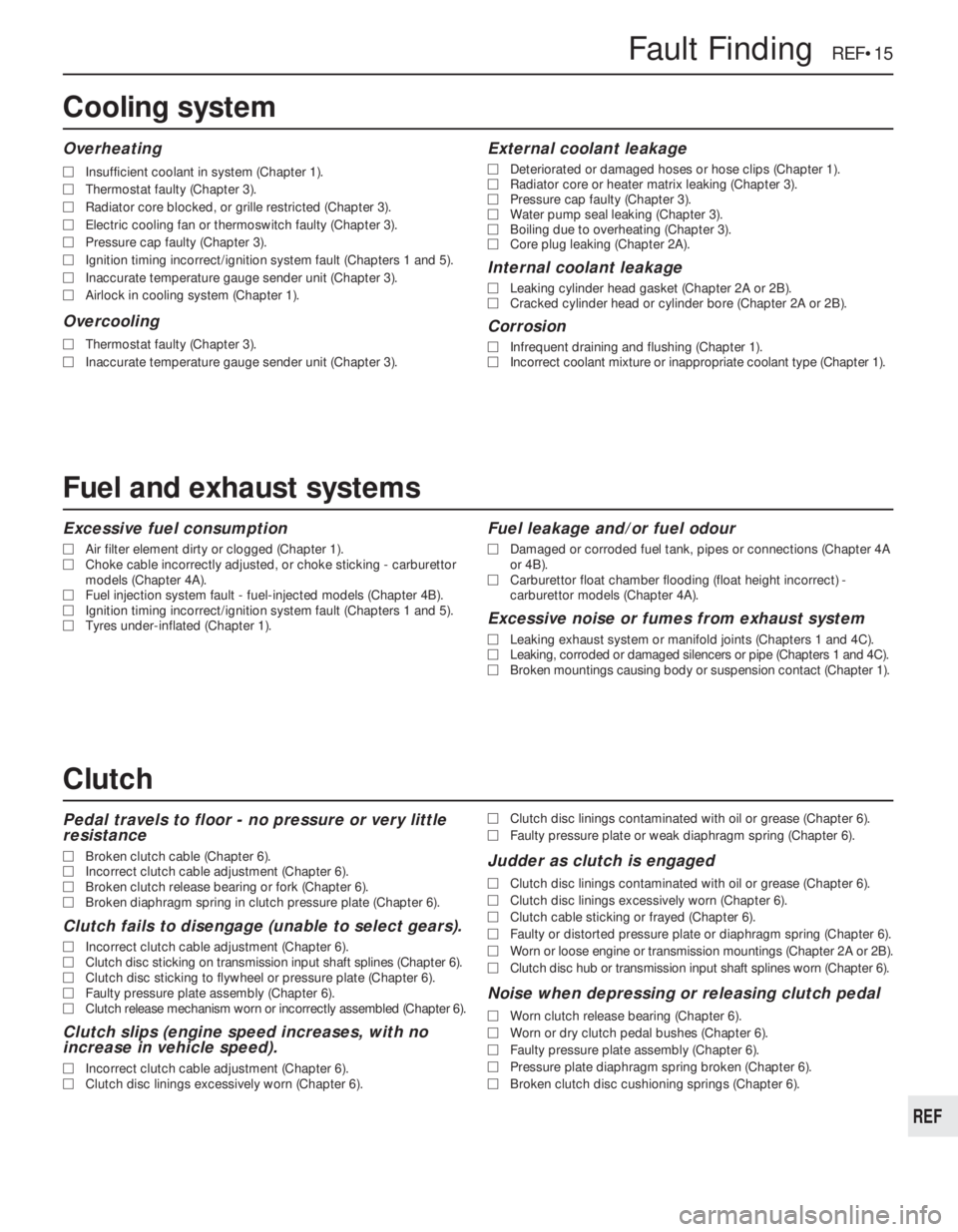
Excessive fuel consumption
MAir filter element dirty or clogged (Chapter 1).
MChoke cable incorrectly adjusted, or choke sticking - carburettor
models (Chapter 4A).
MFuel injection system fault - fuel-injected models (Chapter 4B).
MIgnition timing incorrect/ignition system fault (Chapters 1 and 5).
MTyres under-inflated (Chapter 1).
Fuel leakage and/or fuel odour
MDamaged or corroded fuel tank, pipes or connections (Chapter 4A
or 4B).
MCarburettor float chamber flooding (float height incorrect) -
carburettor models (Chapter 4A).
Excessive noise or fumes from exhaust system
MLeaking exhaust system or manifold joints (Chapters 1 and 4C).
MLeaking, corroded or damaged silencers or pipe (Chapters 1 and 4C).
MBroken mountings causing body or suspension contact (Chapter 1).
Pedal travels to floor - no pressure or very little
resistance
MBroken clutch cable (Chapter 6).
MIncorrect clutch cable adjustment (Chapter 6).
MBroken clutch release bearing or fork (Chapter 6).
MBroken diaphragm spring in clutch pressure plate (Chapter 6).
Clutch fails to disengage (unable to select gears).
MIncorrect clutch cable adjustment (Chapter 6).
MClutch disc sticking on transmission input shaft splines (Chapter 6).
MClutch disc sticking to flywheel or pressure plate (Chapter 6).
MFaulty pressure plate assembly (Chapter 6).
MClutch release mechanism worn or incorrectly assembled (Chapter 6).
Clutch slips (engine speed increases, with no
increase in vehicle speed).
MIncorrect clutch cable adjustment (Chapter 6).
MClutch disc linings excessively worn (Chapter 6).MClutch disc linings contaminated with oil or grease (Chapter 6).
MFaulty pressure plate or weak diaphragm spring (Chapter 6).
Judder as clutch is engaged
MClutch disc linings contaminated with oil or grease (Chapter 6).
MClutch disc linings excessively worn (Chapter 6).
MClutch cable sticking or frayed (Chapter 6).
MFaulty or distorted pressure plate or diaphragm spring (Chapter 6).
MWorn or loose engine or transmission mountings (Chapter 2A or 2B).
MClutch disc hub or transmission input shaft splines worn (Chapter 6).
Noise when depressing or releasing clutch pedal
MWorn clutch release bearing (Chapter 6).
MWorn or dry clutch pedal bushes (Chapter 6).
MFaulty pressure plate assembly (Chapter 6).
MPressure plate diaphragm spring broken (Chapter 6).
MBroken clutch disc cushioning springs (Chapter 6).
Fault Finding REF•15
REF
Overheating
MInsufficient coolant in system (Chapter 1).
MThermostat faulty (Chapter 3).
MRadiator core blocked, or grille restricted (Chapter 3).
MElectric cooling fan or thermoswitch faulty (Chapter 3).
MPressure cap faulty (Chapter 3).
MIgnition timing incorrect/ignition system fault (Chapters 1 and 5).
MInaccurate temperature gauge sender unit (Chapter 3).
MAirlock in cooling system (Chapter 1).
Overcooling
MThermostat faulty (Chapter 3).
MInaccurate temperature gauge sender unit (Chapter 3).
External coolant leakage
MDeteriorated or damaged hoses or hose clips (Chapter 1).
MRadiator core or heater matrix leaking (Chapter 3).
MPressure cap faulty (Chapter 3).
MWater pump seal leaking (Chapter 3).
MBoiling due to overheating (Chapter 3).
MCore plug leaking (Chapter 2A).
Internal coolant leakage
MLeaking cylinder head gasket (Chapter 2A or 2B).
MCracked cylinder head or cylinder bore (Chapter 2A or 2B).
Corrosion
MInfrequent draining and flushing (Chapter 1).
MIncorrect coolant mixture or inappropriate coolant type (Chapter 1).
Cooling system
Clutch
Fuel and exhaust systems
Page 260 of 525
Glossary of Technical Terms REF•21
REF
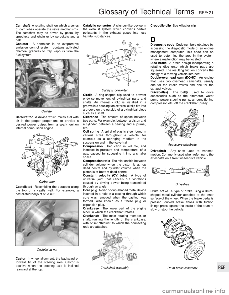
CamshaftA rotating shaft on which a series
of cam lobes operate the valve mechanisms.
The camshaft may be driven by gears, by
sprockets and chain or by sprockets and a
belt.
CanisterA container in an evaporative
emission control system; contains activated
charcoal granules to trap vapours from the
fuel system.
CarburettorA device which mixes fuel with
air in the proper proportions to provide a
desired power output from a spark ignition
internal combustion engine.
CastellatedResembling the parapets along
the top of a castle wall. For example, a
castellated balljoint stud nut.
CastorIn wheel alignment, the backward or
forward tilt of the steering axis. Castor is
positive when the steering axis is inclined
rearward at the top.Catalytic converterA silencer-like device in
the exhaust system which converts certain
pollutants in the exhaust gases into less
harmful substances.
CirclipA ring-shaped clip used to prevent
endwise movement of cylindrical parts and
shafts. An internal circlip is installed in a
groove in a housing; an external circlip fits into
a groove on the outside of a cylindrical piece
such as a shaft.
ClearanceThe amount of space between
two parts. For example, between a piston and
a cylinder, between a bearing and a journal,
etc.
Coil springA spiral of elastic steel found in
various sizes throughout a vehicle, for
example as a springing medium in the
suspension and in the valve train.
CompressionReduction in volume, and
increase in pressure and temperature, of a
gas, caused by squeezing it into a smaller
space.
Compression ratioThe relationship between
cylinder volume when the piston is at top
dead centre and cylinder volume when the
piston is at bottom dead centre.
Constant velocity (CV) jointA type of
universal joint that cancels out vibrations
caused by driving power being transmitted
through an angle.
Core plugA disc or cup-shaped metal device
inserted in a hole in a casting through which
core was removed when the casting was
formed. Also known as a freeze plug or
expansion plug.
CrankcaseThe lower part of the engine
block in which the crankshaft rotates.
CrankshaftThe main rotating member, or
shaft, running the length of the crankcase,
with offset “throws” to which the connecting
rods are attached.Crocodile clipSee Alligator clip
DDiagnostic codeCode numbers obtained by
accessing the diagnostic mode of an engine
management computer. This code can be
used to determine the area in the system
where a malfunction may be located.
Disc brakeA brake design incorporating a
rotating disc onto which brake pads are
squeezed. The resulting friction converts the
energy of a moving vehicle into heat.
Double-overhead cam (DOHC)An engine
that uses two overhead camshafts, usually
one for the intake valves and one for the
exhaust valves.
Drivebelt(s)The belt(s) used to drive
accessories such as the alternator, water
pump, power steering pump, air conditioning
compressor, etc. off the crankshaft pulley.
DriveshaftAny shaft used to transmit
motion. Commonly used when referring to the
axleshafts on a front wheel drive vehicle.
Drum brakeA type of brake using a drum-
shaped metal cylinder attached to the inner
surface of the wheel. When the brake pedal is
pressed, curved brake shoes with friction
linings press against the inside of the drum to
slow or stop the vehicle.
Castellated nut
Catalytic converter
Crankshaft assembly
Carburettor
Canister
Drum brake assembly
Accessory drivebelts
Driveshaft
Page 261 of 525
REF•22Glossary of Technical Terms
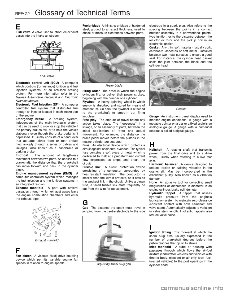
EEGR valveA valve used to introduce exhaust
gases into the intake air stream.
Electronic control unit (ECU)A computer
which controls (for instance) ignition and fuel
injection systems, or an anti-lock braking
system. For more information refer to the
Haynes Automotive Electrical and Electronic
Systems Manual.
Electronic Fuel Injection (EFI)A computer
controlled fuel system that distributes fuel
through an injector located in each intake port
of the engine.
Emergency brakeA braking system,
independent of the main hydraulic system,
that can be used to slow or stop the vehicle if
the primary brakes fail, or to hold the vehicle
stationary even though the brake pedal isn’t
depressed. It usually consists of a hand lever
that actuates either front or rear brakes
mechanically through a series of cables and
linkages. Also known as a handbrake or
parking brake.
EndfloatThe amount of lengthwise
movement between two parts. As applied to a
crankshaft, the distance that the crankshaft
can move forward and back in the cylinder
block.
Engine management system (EMS)A
computer controlled system which manages
the fuel injection and the ignition systems in
an integrated fashion.
Exhaust manifoldA part with several
passages through which exhaust gases leave
the engine combustion chambers and enter
the exhaust pipe.
FFan clutchA viscous (fluid) drive coupling
device which permits variable engine fan
speeds in relation to engine speeds.Feeler bladeA thin strip or blade of hardened
steel, ground to an exact thickness, used to
check or measure clearances between parts.
Firing orderThe order in which the engine
cylinders fire, or deliver their power strokes,
beginning with the number one cylinder.
Flywheel A heavy spinning wheel in which
energy is absorbed and stored by means of
momentum. On cars, the flywheel is attached
to the crankshaft to smooth out firing
impulses.
Free playThe amount of travel before any
action takes place. The “looseness” in a
linkage, or an assembly of parts, between the
initial application of force and actual
movement. For example, the distance the
brake pedal moves before the pistons in the
master cylinder are actuated.
FuseAn electrical device which protects a
circuit against accidental overload. The typical
fuse contains a soft piece of metal which is
calibrated to melt at a predetermined current
flow (expressed as amps) and break the
circuit.
Fusible linkA circuit protection device
consisting of a conductor surrounded by
heat-resistant insulation. The conductor is
smaller than the wire it protects, so it acts as
the weakest link in the circuit. Unlike a blown
fuse, a failed fusible link must frequently be
cut from the wire for replacement.
GGapThe distance the spark must travel in
jumping from the centre electrode to the sideelectrode in a spark plug. Also refers to the
spacing between the points in a contact
breaker assembly in a conventional points-
type ignition, or to the distance between the
reluctor or rotor and the pickup coil in an
electronic ignition.
GasketAny thin, soft material - usually cork,
cardboard, asbestos or soft metal - installed
between two metal surfaces to ensure a good
seal. For instance, the cylinder head gasket
seals the joint between the block and the
cylinder head.
GaugeAn instrument panel display used to
monitor engine conditions. A gauge with a
movable pointer on a dial or a fixed scale is an
analogue gauge. A gauge with a numerical
readout is called a digital gauge.
HHalfshaftA rotating shaft that transmits
power from the final drive unit to a drive
wheel, usually when referring to a live rear
axle.
Harmonic balancerA device designed to
reduce torsion or twisting vibration in the
crankshaft. May be incorporated in the
crankshaft pulley. Also known as a vibration
damper.
HoneAn abrasive tool for correcting small
irregularities or differences in diameter in an
engine cylinder, brake cylinder, etc.
Hydraulic tappetA tappet that utilises
hydraulic pressure from the engine’s
lubrication system to maintain zero clearance
(constant contact with both camshaft and
valve stem). Automatically adjusts to variation
in valve stem length. Hydraulic tappets also
reduce valve noise.
IIgnition timingThe moment at which the
spark plug fires, usually expressed in the
number of crankshaft degrees before the
piston reaches the top of its stroke.
Inlet manifoldA tube or housing with
passages through which flows the air-fuel
mixture (carburettor vehicles and vehicles with
throttle body injection) or air only (port fuel-
injected vehicles) to the port openings in the
cylinder head.
Exhaust manifold
Feeler blade
Adjusting spark plug gap
Gasket
EGR valve
Page 264 of 525
AABS components- 9•2, 9•16
Accelerator cable- 4A•5, 4B•9
Accelerator pedal- 4A•5
Acknowledgements- 0•4
Aerial- 12•17
Air cleaner- 1•3, 1•13, 4A•3, 4B•4
Air box- 4B•5
Air pump/cut off valve- 4C•2
Air temp control- 4B•5
Air vents- 3•8
Airbag- 12•19
Airflow meters- 4B•12
Alternator- 5•5
Alternator V-belt check- 1•12
Anti theft alarm- 12•19
Anti-roll bars- 10•8, 10•13, 10•17
Antifreeze mixture- 0•12, 0•17, 1•2, 3•3
ATF- 0•17, 1•2, 1•11, 7B•3
Automatic choke unit- 4A•9
Automatic transmission- 7B•1 et seq
cooler pipes and hoses - 7B•5
ECU - 7B•5
fault diagnosis - REF•12, REF•16
fluid - 0•17, 1•2, 1•11, 7B•3
kickdown switch - 7B•3
removal and refitting - 7B•6
selector control cable - 7B•4
speed sensors - 7B•6
starter inhibitor switch - 7B•3
temperature sensor - 7B•5
BBattery- 0•6, 0•15, 5•5
Bearings (engine)- 2A•31
Bleeding the brakes- 9•3
Bleeding the power steering- 10•22
Blower motor- 3•7
Body damage- 11•2
Body electrical systems - 12•1 et seq
Bodywork and fittings- 11•1 et seq
Bonnet- 11•4
Bonnet lock/release cable- 11•4
Boot lid- 11•4
Boot lid lock- 11•5
Bores- 2A•33
Brake checks- 1•12,
Braking system- 9•1 et seq
ABS components - 9•2, 9•16
backplate - 9•12
bleeding the brakes - 9•3
brake caliper - 9•8
brake disc - 9•10
brake drum - 9•11
brake fluid pipes and hoses - 9•18
brake lamp switch - 12•5
brake pads - 9•4
brake pedal - 9•21
brake shoes - 9•6
disc shield - 9•13
fault diagnosis - REF•12, REF•17
fluid - 0•13, 0•17handbrake adjustment - 9•18
handbrake cables - 9•19
handbrake lever - 9•20
master cylinder - 9•13
pressure valves - 9•18
vacuum servo unit - 9•15
wheel cylinder - 9•11
Bulbs- 12•2, 12•7, 12•11
Bumpers- 11•11
CCables:
bonnet release - 11•4
clutch - 6•2
handbrake - 9•19
selector automatic transmission - 7B•4
speedometer - 12•18
throttle - 4A•5, 4B•9
Caliper (brake)- 9•8
Camber- 10•1, 10•24
Camshaft- 2A•19, 2B•6
Camshaft housing- 2A•18
Camshaft oil seals- 2A•18
Capacities- 1•2
Carbon canister- 4C•4
Carburettor- 4A•5, 4A•11
Carpets- 11•2
Castor- 10•1, 10•24
Catalytic converter- 4C•3
Central door locking- 12•16
Centre console- 11•18
Cigarette lighter- 12•5
Clock- 12•6
Clutch- 6•1 et seq
cable - 6•2
fault diagnosis - REF•12, REF•15
pedal - 6•3
release bearing - 6•6
removal, inspection and refitting - 6•3
Coil- 5•9
Coil spring (rear)- 10•12, 10•15
Compression test- 2A•8
Computer components- 12•7
Connecting rods- 2A•29
Contents- 0•2
Control units- 4B•16, 7B•5
Conversion factors- REF•2
Coolant- 0•12, 0•17, 1•2, 3•3
Cooling, heating and ventilation systems-
3•1 et seq
blower motor - 3•7
coolant level sensor - 3•5
coolant pump - 3•4
cooling fan - 3•5
draining - 3•2
expansion tank - 3•5
fan switch - 3•6
fault diagnosis - REF•12, REF•15
filling - 3•2
flushing - 3•2
heater control panel - 3•6
heater matrix - 3•7
radiator - 3•3temperature gauge sender - 3•6
thermostat - 3•4
vents - 3•8
Courtesy lamp switch- 12•5
Crankcase ventilation system- 2A•7
Crankshaft- 2A•31
Crankshaft oil seals- 2A•26, 2B•6, 2B•9
Cylinder bores- 2A•33
Cylinder head- 2A•19, 2A•22, 2B•7DDents- 11•2
Depressurising fuel system- 4B•5
Differential bearing oil seal- 7A•3
Dimensions and weights- REF•1
Disc (brake)- 9•10
Distributor- 5•10
Door- 11•6
handle - 11•7
inner trim panel - 11•6
lock key battery - 1•13
mirror - 11•11
Driveshafts- 8•1 et seq
fault diagnosis - REF•12, REF•16
gaiter - 8•4
joint renewal - 8•4
Drum (brake)- 9•11
EEarth fault finding- 12•2
ECU’s - 4B•16, 7B•5
EGR components- 4C•2
Electric windows- 12•15
Electrical fault finding- 12•2
Electrical system (body)- 12•1 et seq
Electrical system- 0•14, 5•2
Electrical system fault diagnosis- REF•12,
REF•18
Electronic control units- 4B•16, 7B•5
Engine:
bearings - 2A•31
camshaft - 2A•19, 2B•6
camshaft housing - 2A•18
camshaft oil seals - 2A•18, 2B•6
codes - 2A•1, 2B•1
compartment - 0•10, 1•5
compression test - 2A•8
connecting rods - 2A•29
crankcase ventilation - 2A•7
crankshaft - 2A•31
crankshaft oil seals - 2A•26, 2B•6, 2B•9
cylinder bores - 2A•33
cylinder head - 2A•19, 2A•22, 2B•7
dismantling - 2A•12
DOHC - 2B•1 et seq
electrical systems - 5•1 et seq
fault diagnosis - REF•12, REF•13
flexplate (automatic transmission) - 2A•26
flywheel - 2A•26
main and big-end bearings - 2A•31
mountings (engine/transmission) - 2A•12,
2B•3
Index REF•25
REF
Note:References throughout this index are in the form - “Chapter number” • “page number”
Page 265 of 525
oil and filter renewal - 0•17, 1•2, 1•9
oil cooler - 2B•10
oil level - 0•12
oil pump - 2A•28, 2B•9
piston rings - 2A•30
piston/connecting rod - 2A•29
removal - 2A•8, 2B•3
SOHC - 2A•1 et seq
sump - 2A•27, 2B•9
timing belt - 2A•13, 2B•3, 2B•6
undershield - 11•13
valve lifters - 2A•24, 2B•9
valves - 2A•5, 2B•2
Environmental considerations- REF•4
Exhaust manifold- 4C•5
Exhaust system check- 1•11, 4C•5
Expansion tank- 3•5
FFan (radiator)- 3•5
Fault diagnosis- REF•12 et seq
automatic transmission - REF•12, REF•16
braking system - REF•12, REF•17
clutch - REF•12, REF•15
cooling system - REF•12, REF•15
driveshafts - REF•12, REF•16
electrical system - REF•12, REF•18
engine - REF•12, REF•13
fuel and exhaust systems - REF•12, REF•15
manual transmission - REF•12, REF•16
steering - REF•12, REF•17
suspension - REF•12, REF•17
Flexplate (automatic transmission)- 2A•26
Flushing (cooling system)- 3•2
Flywheel- 2A•26
Foglamp- 12•11
Fuel and exhaust (carburettor) systems-
4A•1 et seq
Fuel and exhaust (fuel injection) systems-
4B•1 et seq
Fuel and exhaust systems - emissions-
4C•1 et seq
Fuel and exhaust systems:
accelerator cable - 4A•5
accelerator pedal - 4A•5
air box - 4B•5
air cleaner - 1•3, 1•13, 4A•3, 4B•4
air pump/cut off valve - 4C•2
air temperature control - 4B•5
airflow meters - 4B•12
automatic choke - 4A•9
carbon canister - 4C•4
carburettor - 4A•5, 4A•11
catalytic converter - 4C•3
control unit - 4B•16
depressurising fuel system - 4B•5
EGR components - 4C•2
exhaust manifold - 4C•5
exhaust system check - 1•11, 4C•5
fault diagnosis - REF•12, REF•15
filler cap - 11•13
fuel filters - 1•3, 1•14, 4B•6
fuel flow damper - 4B•8
fuel injector(s) - 4B•13
fuel level sender unit - 4A•4, 4B•8
fuel pressure regulator - 4B•10
fuel pump - 4A•3, 4B•6fuel tank - 4A•4, 4B•7
fuel vapour separator - 4A•4
idle speed/mixture adjustment - 4A•7,
4A•12, 4B•9, 4B•11
inlet manifold - 4A•12, 4B•17
knock sensor - 4B•17
lambda sensor - 4C•4
manifolds - 4A•12, 4B•17, 4C•5
mixture (CO) - 4A•7, 4A•12, 4B•9
oxygen sensor - 4C•4
Pierburg 2E3 - 4A•5
potentiometer - 4B•12, 4B•16
throttle cable - 4A•5
throttle pedal - 4A•5
Fuses- 12•1, 12•3
GGear selector linkage- 7A•2
Gearbox - see Manual or Automatic
transmission
Gearbox oil- 0•17, 1•2, 1•15
Gearchange lever- 7A•3
Glass- 11•9
Glossary of technical terms- REF•20
Glove compartment- 11•18
HHandbrake adjustment- 9•18
Handbrake cables- 9•19
Handbrake lever- 9•20
Handles (door)- 11•7
Hazard warning switch- 12•4
Headlamp alignment- 12•10
Headlamp unit- 12•9
Headlining- 11•19
Heater blower motor switch- 12•4
Heater control panel- 3•6
Heater matrix- 3•7
Heating systems- 3•1 et seq
Horn- 12•8
Hose and fluid leak check- 0•9, 1•9
Hoses brake- 9•18
IIdle speed/mixture/adjustment- 4A•7,
4A•12, 4B•9, 4B•11
Ignition coil- 5•9
Ignition switch- 12•3
Ignition system- 5•2
Igniton timing- 5•2, 5•13
Indicator lamps- 12•11
Indicator switch- 12•4
Injector(s)- 4B•13
Inlet manifold- 4A•12, 4B•17
Input shaft (clutch) oil seal- 7A•4
Instrument panel- 12•6
Interior lamps- 12•8
Interior trim panels- 11•14
Introduction to the Vauxhall Cavalier- 0•4
JJacking and vehicle support- REF•5
Jump starting- 0•7
KKickdown switch - 7B•3
Knock sensor- 4B•17
LLambda sensor- 4C•4
Lamps- 12•8, 12•9
Leaks- 0•9, 1•9
Light switch- 12•4
Locks bonnet- 11•4
Locks door- 11•8
Locks tailgate- 11•6
Lubricants and fluids- 0•17
MMain and big-end bearings- 2A•31
Maintenance - see Routine maintenance
Maintenance schedule- 1•4
Manifolds- 4A•12, 4B•17, 4C•5
Manual transmission- 7A•1 et seq
differential bearing oil seals - 7A•3
fault diagnosis - REF•12, REF•16
gear selector linkage - 7A•2
gearbox oil - 0•17, 1•2, 1•15
gearchange lever - 7A•3
input shaft (clutch) oil seal - 7A•4
overhaul -7A•5
removal and refitting - 7A•4
reversing lamp switch - 7A•6
speedometer drive - 7A•6
Master cylinder (brake)- 9•13
Mirrors- 11•11
Mixture (CO)- 4A•7, 4B•9
MOT test checks- REF•8
Mountings (engine/transmission)- 2A•12,
2B•3
NNumber plate lamp- 12•11
OOil change- 0•17, 1•2, 1•9
Oil cooler- 2B•10
Oil filter- 1•2, 1•9
Oil pressure warning lamp switch- 12•5
Oil pump- 2A•28, 2B•9
Oil seals:
differential bearing - 7A•3
general - REF •4
camshaft - 2A•18, 2B•6
crankshaft - 2A•26, 2B•6, 2B•9
Oils- 0•17, 1•2
Open-circuit, finding - 12•2
Oxygen sensor- 4C•4
PPads (brake)- 9•4
Paintwork damage- 11•2
Parts- REF•3
Pedals
brake - 9•21
clutch - 6•3
throttle - 4A•5
REF•26Index
Page 266 of 525
Pierburg 2E3 carburettor- 4A•5
Piston rings- 2A•30
Piston/connecting rod- 2A•29
Plastic components- 11•3
Potentiometer- 4B•12, 4B•16
Power steering fluid - 0•14, 0•17, 1•2, 1•12
Power steering pump- 10•22
Power steering system bleeding- 10•22
Punctures- 0•8
RRadiator- 3•3
Radiator cooling fan- 3•5
Radiator grille- 11•12
Radio/cassette anti theft system- REF•5
Radio/cassette player- 12•18
Rear hub- 10•10, 10•15
Rear lamps- 12•11
Rear suspension assembly- 10•15
Relays- 12•3
Release bearing (clutch)- 6•6
Repair procedures- REF •4
Respraying- 11•2
Reversing lamp switch- 7A•6
Road test- 1•13
Roll bars- 10•8, 10•13, 10•17
Routine maintenance - 1•1 et seq
SSafety first!- 0•5
Scratches- 11•2
Seat belts- 11•21
Seats- 11•20, 11•22
Seats heated- 12•6
Selector cable (automatics)- 7B•4
Selector lever- 7B•4
Sender unit fuel level- 4A•4, 4B•8
Sender units (temperature gauge)- 3•6
Servicing - see Routine maintenance
Servo unit (braking system)- 9•15
Shock absorber- 10•11
Shoes (brake)- 9•6
Short-circuit finding- 12•2
Spark plugs- 1•3, 1•14, 1•16
Speakers- 12•17
Speedometer cable- 12•18
Speedometer drive- 7A•6
Starter inhibitor switch- 7B•3
Starter motor- 5•8
Starting problems- 0•6
Steering wheel alignment- 10•1, 10•24
Steering- 10•1 et seq
camber - 10•1 10•24
castor - 10•1, 10•24
column - 10•18
damper - 10•21
fault diagnosis - REF•12, REF•17gear - 10•21
power steering system bleeding - 10•22
power steering fluid - 0•17, 1•2
power steering pump - 10•22
shaft rubber coupling - 10•18
tie-rod end - 10•23
toe setting - 10•1, 10•24
wheel - 10•17
wheel bearing - 10•4, 10•9, 10•14
wheel with airbag - 12•20
Stub axle- 10•13
Subframe- 10•5
Sump- 2A•27, 2B•9
Sunroof- 11•13
Sunroof motor- 12•18
Sunroof switch- 12•5
Suspension- 10•1 et seq
anti-roll bars - 10•8, 10•13, 10•17
assembly (rear) - 10•15
coil spring (rear) - 10•12, 10•15
fault diagnosis - REF•12, REF•17
level control system - 10•14
lower arm (front) - 10•7
rear hub - 10•10, 10•15
shock absorber - 10•11
strut (front) - 10•6
stub axle - 10•13
sub frame - 10•5
trailing arms - 10•12, 10•16
wheel bearing - 10•4, 10•9, 10•14
Suspension/steering checks- 1•10
Switches:
brake lamp - 12•5
cooling fan - 3•6
courtesy lamp - 12•5
electric door mirror - 12•5
handbrake warning lamp - 12•5
hazard warning - 12•4
heater blower motor - 12•4
ignition - 12•3
indicator - 12•4
kickdown - 7B•3
lights - 12•4
luggage compartment - 12•5
oil pressure warning lamp - 12•5
push button - 12•4
reversing lamp - 7A•6
starter inhibitor - 7B•3
sunroof - 12•5
TTailgate- 11•5
Temperature gauge sender- 3•6
Temperature sensor (automatics)- 7B•5
Thermostat- 3•4
Throttle cable- 4A•5, 4B•9
Throttle pedal- 4A•5Tie-rod end- 10•23
Timing- 5•2, 5•13
Timing belt- 1•16, 2A•13, 2B•3, 2B•6
Toe setting- 10•1, 10•24
Tools and working facilities- REF•4, REF•6,
REF•7
Towing- 0•9
Trim panel (door)- 11•6
Tyre checks- 0•16, 0•17
Tyre pressures- 0•17
UUnderbody- 11•1
Underbody views- 1•7
Underbonnet views- 0•10, 1•5
Upholstery and carpets- 11•2
VVacuum servo unit (braking system)- 9•15
Valve lifters- 2A•24, 2B•9
Valves- 2A•5, 2B•2
Vehicle identification numbers- REF•3
Ventilation system- 3•1 et seq
Vents- 3•8
WWasher fluid- 0•13, 1•2
Washers- 12•13, 12•15
Water pump- 3•4
Weekly checks- 0•10et seq
Wheelalignment- 10•1, 10•24
Wheel arch liners- 11•12
Wheel bearing- 10•4, 10•9, 10•14
Wheel changing- 0•8
Wheel cylinder- 9•11
Window glass- 11•9
Window regulator- 11•10
Windscreen- 11•9, 11•12
Wiper blades- 0•15, 12•13
Wiper motors- 12•14
Wiring diagrams- 12•22 et seq
Index REF•27
REF