service OPEL CALIBRA 1988 Service Repair Manual
[x] Cancel search | Manufacturer: OPEL, Model Year: 1988, Model line: CALIBRA, Model: OPEL CALIBRA 1988Pages: 525, PDF Size: 58.26 MB
Page 16 of 525
1General information and
precautions
The electrical system is of 12-volt negative
earth type. Power for the lights and all
electrical accessories is supplied by a
lead/acid type battery, which is charged by
the alternator.
This Chapter covers repair and service
procedures for the various electrical
components not associated with engine.
Information on the battery, alternator and
starter motor can be found in Chapter 5.
It should be noted that, before working on
any component in the electrical system, the
battery negative terminal should first be
disconnected, to prevent the possibility of
electrical short-circuits and/or fires.
Whenever the occasion arises, carefully
check the routing of the wiring harness,
ensuring that it is correctly secured by the
clips or ties provided so that it cannot chafe
against other components. Carefully check
points such as the clutch cable bracket,
clutch housing and harness support bracket,
the inlet manifold, the horn mounting bracket,
the starter motor terminals, and the rear
bumper and number plate lamp.
If evidence is found of the harness having
chafed against other components, repair the
damage and ensure that the harness is
secured or protected so that the problem
cannot occur again.
2Electrical fault-finding -
general information
Note:Refer to the precautions given in “Safety
first!” (at the beginning of this manual) and to
Section 1 of this Chapter before starting work.
The following tests relate to testing of the main
electrical circuits, and should not be used to
test delicate electronic circuits (such as anti-
lock braking systems), particularly where an
electronic control module is used.
A typical electrical circuit consists of an
electrical component, any switches, relays,
motors, fuses, fusible links or circuit breakers
related to that component, and the wiring and
connectors that link the component to boththe battery and the chassis. To help to
pinpoint a problem in an electrical circuit,
wiring diagrams are included at the end of this
Chapter.
Before attempting to diagnose an electrical
fault, first study the appropriate wiring
diagram, to obtain a complete understanding
of the components included in the particular
circuit concerned. The possible sources of a
fault can be narrowed down by noting
whether other components related to the
circuit are operating properly. If several
components or circuits fail at one time, the
problem is likely to be related to a shared fuse
or earth connection.
Electrical problems usually stem from
simple causes, such as loose or corroded
connections, a faulty earth connection, a
blown fuse, a melted fusible link, or a faulty
relay (refer to Section 3 for details of testing
relays). Visually inspect the condition of all
fuses, wires and connections in a problem
circuit before testing the components. Use
the wiring diagrams to determine which
terminal connections will need to be checked,
to pinpoint the trouble-spot.
The basic tools required for electrical fault-
finding include the following:
a)a circuit tester or voltmeter (a 12-volt bulb
with a set of test leads can also be used
for certain tests).
b)a self-powered test light (sometimes
known as a continuity tester).
c)an ohmmeter (to measure resistance).
d)a battery.
e)a set of test leads.
f)a jumper wire, preferably with a circuit
breaker or fuse incorporated, which can
be used to bypass suspect wires or
electrical components.
Before attempting to locate a problem with
test instruments, use the wiring diagram to
determine where to make the connections.
To find the source of an intermittent wiring
fault (usually due to a poor or dirty
connection, or damaged wiring insulation), a
“wiggle” test can be performed on the wiring.
This involves wiggling the wiring by hand, to
see if the fault occurs as the wiring is moved.
It should be possible to narrow down the
source of the fault to a particular section of
wiring. This method of testing can be used in
conjunction with any of the tests described in
the following sub-Sections.
Apart from problems due to poor
connections, two basic types of fault can
occur in an electrical circuit - open-circuit, or
short-circuit.
Open-circuit faults are caused by a break
somewhere in the circuit, which prevents
current from flowing. An open-circuit fault will
prevent a component from working, but will
not cause the relevant circuit fuse to blow.
Short-circuit faults are caused by a “short”
somewhere in the circuit, which allows the
current flowing in the circuit to “escape” along
an alternative route, usually to earth. Short-
circuit faults are normally caused by abreakdown in wiring insulation, which allows a
feed wire to touch either another wire, or an
earthed component such as the bodyshell. A
short-circuit fault will normally cause the
relevant circuit fuse to blow.
Finding an open-circuit
To check for an open-circuit, connect one
lead of a circuit tester or voltmeter to either
the negative battery terminal or a known good
earth.
Connect the other lead to a connector in
the circuit being tested, preferably nearest to
the battery or fuse.
Switch on the circuit, remembering that
some circuits are live only when the ignition
switch is moved to a particular position.
If voltage is present (indicated either by the
tester bulb lighting or a voltmeter reading, as
applicable), this means that the section of the
circuit between the relevant connector and
the battery is problem-free.
Continue to check the remainder of the
circuit in the same fashion.
When a point is reached at which no
voltage is present, the problem must lie
between that point and the previous test point
with voltage. Most problems can be traced to
a broken, corroded or loose connection.
Finding a short-circuit
To check for a short-circuit, first disconnect
the load(s) from the circuit (loads are the
components that draw current from a circuit,
such as bulbs, motors, heating elements, etc.).
Remove the relevant fuse from the circuit,
and connect a circuit tester or voltmeter to the
fuse connections.
Switch on the circuit, remembering that
some circuits are live only when the ignition
switch is moved to a particular position.
If voltage is present (indicated either by the
tester bulb lighting or a voltmeter reading, as
applicable), this means that there is a short-
circuit.
If no voltage is present, but the fuse still
blows with the load(s) connected, this indicates
an internal fault in the load(s).
Finding an earth fault
The battery negative terminal is connected
to “earth” (the metal of the
engine/transmission and the car body), and
most systems are wired so that they only
receive a positive feed. The current returning
through the metal of the car body. This means
that the component mounting and the body
form part of that circuit. Loose or corroded
mountings can therefore cause a range of
electrical faults, ranging from total failure of a
circuit, to a puzzling partial fault. In particular,
lights may shine dimly (especially when
another circuit sharing the same earth point is
in operation). Motors (e.g. wiper motors or the
radiator cooling fan motor) may run slowly,
and the operation of one circuit may have an
affect on another. Note that on many vehicles,
earth straps are used between certain
components, such as the engine/transmission
and the body, usually where there is no metal-
12•2Body electrical systems
Warning: Before carrying out
any work on the electrical
system, read through the
precautions given in “Safety
first!” at the beginning of this manual, and
in Chapter 5.
Caution:If the radio/cassette player fitted
to the vehicle is one with an anti-theft
security code, as the standard unit is, refer
to “Radio/cassette player anti-theft system
- precaution”in the Reference Section of
this manual before disconnecting the
battery.
Page 93 of 525
8Alternator drivebelt -
removal, refitting and adjusting
2
V-belt type (not-ribbed)
Removal
1Disconnect the air inlet trunking from the air
cleaner, and the air box or throttle body, as
applicable, and remove it for improved
access.
2Correct tensioning of the drivebelt will
ensure that it has a long life. Beware,
however, of overtightening, as this can cause
excessive wear in the alternator.
3The belt should be inspected regularly, and
if it is found to be worn, frayed or cracked, it
should be renewed as a precaution against
breakage in service. It is advisable to carry a
spare drivebelt of the correct type in the
vehicle always.
4On models with power steering, the
alternator drivebelt also drives the power
steering pump.
5To remove the belt, on 1.8 and 2.0 litre
models first remove the power steering pump
drivebelt, as described in Chapter 10.
6Loosen the two alternator mounting nuts
and bolts sufficiently to allow the alternator to
be pivoted in towards the engine.
7Slide the belt from the pulleys.
Refitting
8Ensure that the correct type of belt is used,
if it is being renewed. Fit the belt around the
pulleys. Take up the slack in the belt byswinging the alternator away from the engine
and lightly tightening the mounting nuts and
bolts.
Adjusting
9Although special tools are available for
measuring the belt tension, a good
approximation can be achieved if the belt is
tensioned so that there is approximately 13.0
mm (0.5 in) of free movement under firm
thumb pressure at the mid-point of the
longest run between pulleys.
10With the mounting bolts just holding the
unit, lever the alternator away from the engine
using a wooden lever at the mounting bracket
end until the correct tension is achieved. Then
tighten the mounting nuts and bolts. On no
account lever at the free end of the alternator,
as serious internal damage could be caused.11Where applicable, refit and tension the
power steering pump drivebelt, as described
in Chapter 10.
12Refit the air inlet trunking.
13When a new belt has been fitted, it will
probably stretch slightly when it is first run,
and the tension should be rechecked and if
necessary adjusted after approximately 250
miles (400 km).
Ribbed V-belt type
General
14Later models equipped with power
steering are fitted with a ribbed V-belt type
drivebelt in conjunction with an automatic
tensioning roller. Once the belt is installed, no
further adjustment is necessary as the correct
tension is maintained by the automatic
tensioning roller. Removal and refitting
procedures are as follows.
Removal
15For improved access, remove the air
cleaner assembly and air inlet trunking.
16If the original drivebelt is to be refitted, mark
the rotational direction on the belt with chalk.
17Using a spanner or socket on the
automatic tensioning roller hexagon, turn the
tensioning roller clockwise (as viewed from the
right-hand side of the car) and hold it in this
position. With the drivebelt tension released,
slip the drivebelt off the pulleys, then allow the
tensioner to return to its original position.
18Support the engine under the sump with a
jack and interposed block of wood.
19From under the car, unbolt the right-hand
engine mounting block from the body.
20Lower the engine support jack just
sufficiently to allow the drivebelt to be
withdrawn from between the mounting block
and the body.
Refitting
21Slip the new drivebelt between the
mounting block and body then raise the
engine, by means of the jack, to its original
position.
22Clean the threads of the mounting block
retaining bolts, apply locking fluid, and refit
the bolts. Tighten the bolts to the specified
torque (see Chapter 2A).
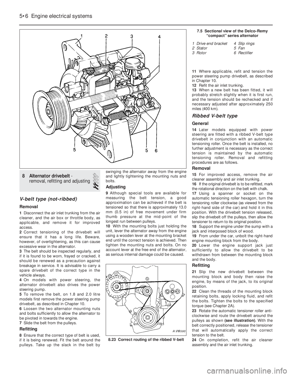
23Rotate the automatic tensioner roller anti-
clockwise and route the drivebelt around the
pulleys as shown (see illustration). With the
belt correctly positioned, release the tensioner
that will automatically apply the correct
tension to the belt.
24On completion, refit the air cleaner
assembly and the air inlet trunking.
5•6Engine electrical systems
7.5 Sectional view of the Delco-Remy
“compact” series alternator
1 Drive end bracket
2 Stator
3 Rotor4 Slip rings
5 Fan
6 Rectifier
8.23 Correct routing of the ribbed V-belt
Page 94 of 525
9Alternator-removal and
refitting
3
Note: Refer to Section 3 before proceeding
Except ‘compact’ series
alternators
Removal
1Disconnect the battery leads.
2Disconnect the air trunking from the air
cleaner, and the air box or throttle body, as
applicable, and remove it for improved
access.
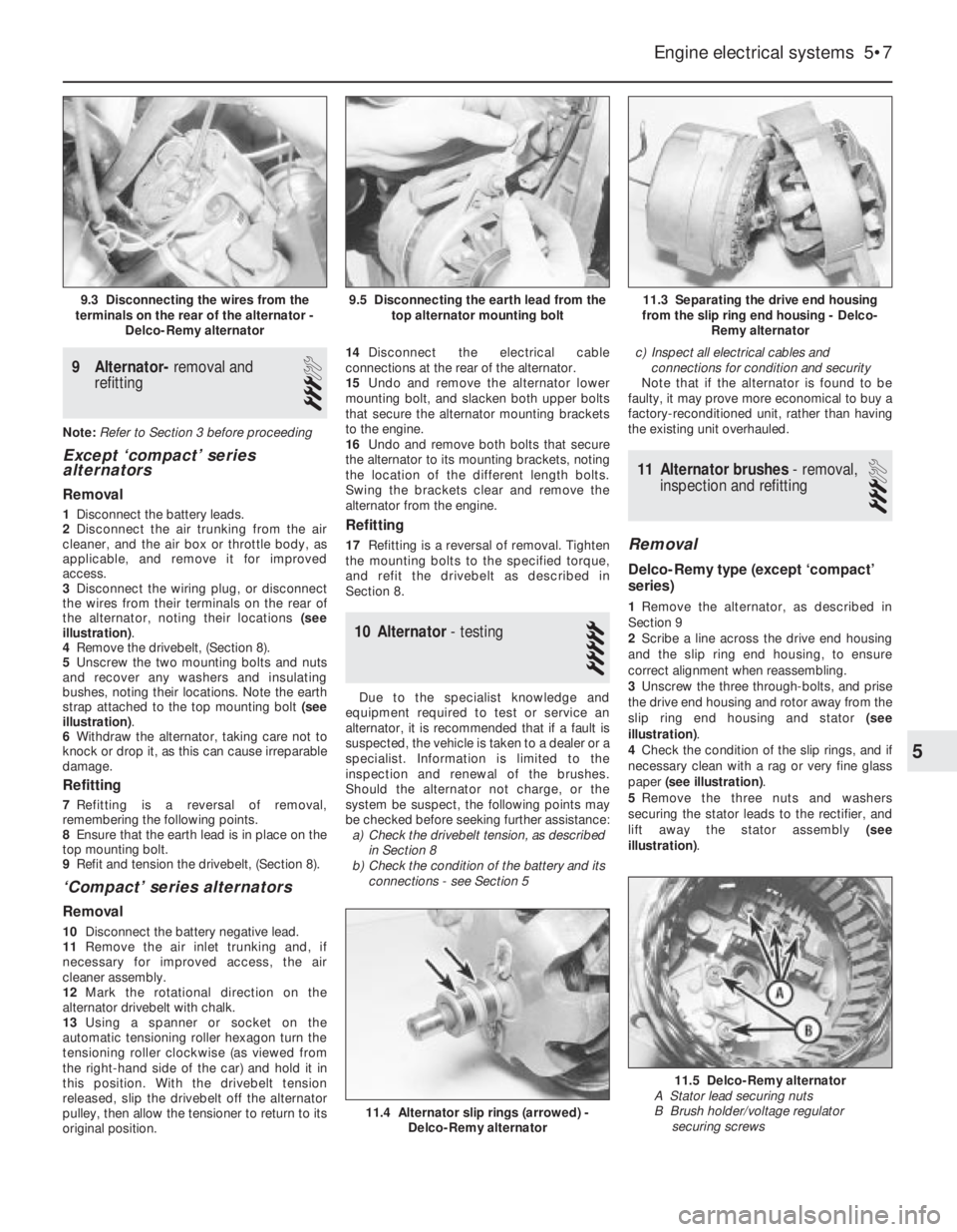
3Disconnect the wiring plug, or disconnect
the wires from their terminals on the rear of
the alternator, noting their locations (see
illustration).
4Remove the drivebelt, (Section 8).
5Unscrew the two mounting bolts and nuts
and recover any washers and insulating
bushes, noting their locations. Note the earth
strap attached to the top mounting bolt (see
illustration).
6Withdraw the alternator, taking care not to
knock or drop it, as this can cause irreparable
damage.
Refitting
7Refitting is a reversal of removal,
remembering the following points.
8Ensure that the earth lead is in place on the
top mounting bolt.
9Refit and tension the drivebelt, (Section 8).
‘Compact’ series alternators
Removal
10Disconnect the battery negative lead.
11Remove the air inlet trunking and, if
necessary for improved access, the air
cleaner assembly.
12Mark the rotational direction on the
alternator drivebelt with chalk.
13Using a spanner or socket on the
automatic tensioning roller hexagon turn the
tensioning roller clockwise (as viewed from
the right-hand side of the car) and hold it in
this position. With the drivebelt tension
released, slip the drivebelt off the alternator
pulley, then allow the tensioner to return to its
original position.14Disconnect the electrical cable
connections at the rear of the alternator.
15Undo and remove the alternator lower
mounting bolt, and slacken both upper bolts
that secure the alternator mounting brackets
to the engine.
16Undo and remove both bolts that secure
the alternator to its mounting brackets, noting
the location of the different length bolts.
Swing the brackets clear and remove the
alternator from the engine.
Refitting
17Refitting is a reversal of removal. Tighten
the mounting bolts to the specified torque,
and refit the drivebelt as described in
Section 8.
10Alternator -testing
5
Due to the specialist knowledge and
equipment required to test or service an
alternator, it is recommended that if a fault is
suspected, the vehicle is taken to a dealer or a
specialist. Information is limited to the
inspection and renewal of the brushes.
Should the alternator not charge, or the
system be suspect, the following points may
be checked before seeking further assistance:
a)Check the drivebelt tension, as described
in Section 8
b)Check the condition of the battery and its
connections -see Section 5c)Inspect all electrical cables and
connections for condition and security
Note that if the alternator is found to be
faulty, it may prove more economical to buy a
factory-reconditioned unit, rather than having
the existing unit overhauled.
11Alternator brushes -removal,
inspection and refitting
3
Removal
Delco-Remy type (except ‘compact’
series)
1Remove the alternator, as described in
Section 9
2Scribe a line across the drive end housing
and the slip ring end housing, to ensure
correct alignment when reassembling.
3Unscrew the three through-bolts, and prise
the drive end housing and rotor away from the
slip ring end housing and stator (see
illustration).
4Check the condition of the slip rings, and if
necessary clean with a rag or very fine glass
paper (see illustration).
5Remove the three nuts and washers
securing the stator leads to the rectifier, and
lift away the stator assembly (see
illustration).
Engine electrical systems 5•7
11.3 Separating the drive end housing
from the slip ring end housing - Delco-
Remy alternator
11.4 Alternator slip rings (arrowed) -
Delco-Remy alternator
11.5 Delco-Remy alternator
A Stator lead securing nuts
B Brush holder/voltage regulator
securing screws
9.5 Disconnecting the earth lead from the
top alternator mounting bolt9.3 Disconnecting the wires from the
terminals on the rear of the alternator -
Delco-Remy alternator
5
Page 107 of 525
6Bonnet - removal and refitting
2
Removal
1Open the bonnet, and support it in the fully
open position.
2On models fitted with an underbonnet lamp,
disconnect the battery negative lead, then
prise the lamp from the bonnet and disconnect
the wiring. If the bonnet is to be refitted, to aid
routing of the wiring on refitting, tie a length of
string to the end of the wiring. Then withdraw
the wiring through the bonnet and untie the
string, leaving it in position in the bonnet.
3Similarly, disconnect the windscreen
washer fluid hose from the connector in the
bonnet, but tie the string to the connector, to
prevent it from slipping into an inaccessible
position in the bonnet.
4Mark the position of the hinges on the
bonnet.
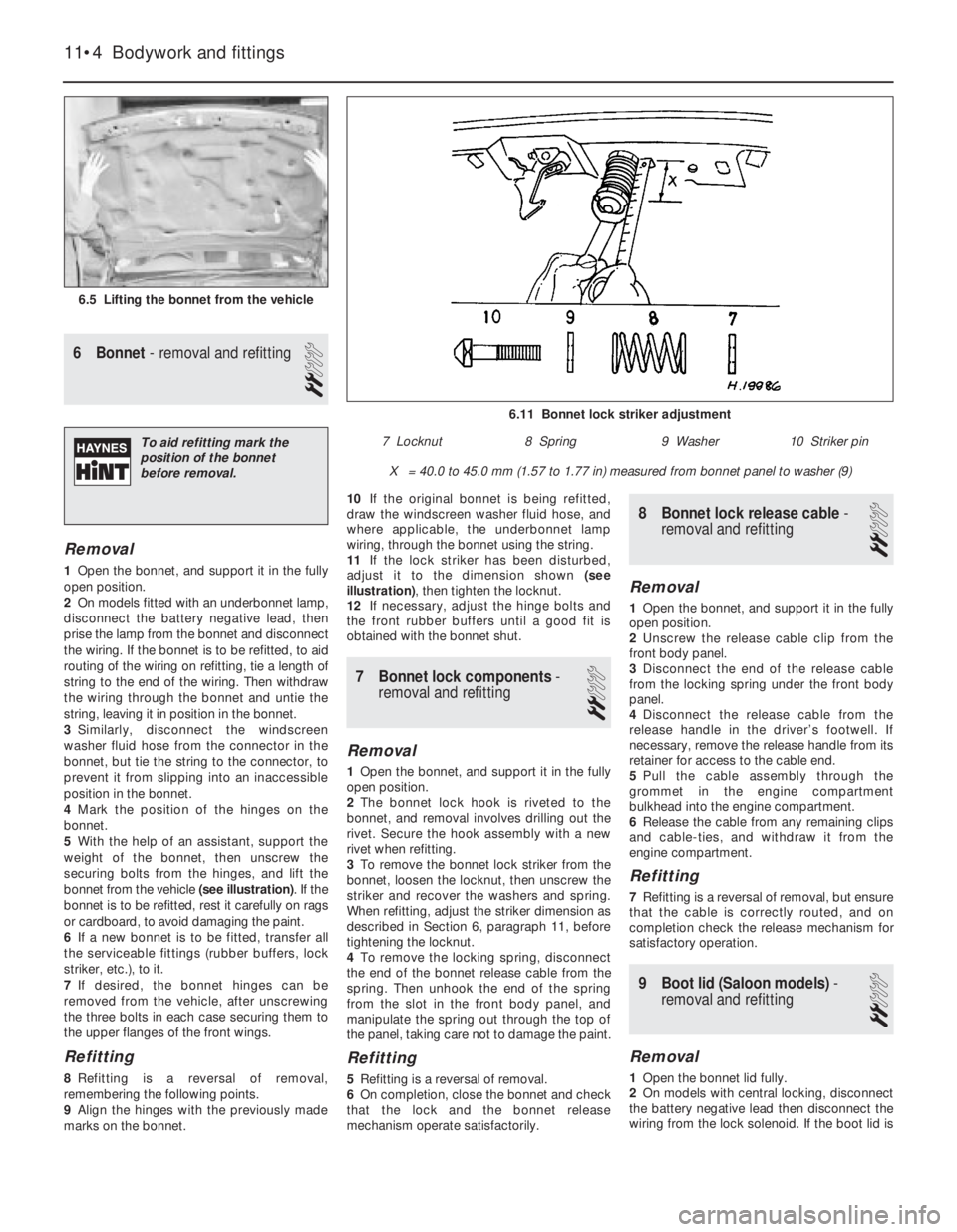
5With the help of an assistant, support the
weight of the bonnet, then unscrew the
securing bolts from the hinges, and lift the
bonnet from the vehicle (see illustration). If the
bonnet is to be refitted, rest it carefully on rags
or cardboard, to avoid damaging the paint.
6If a new bonnet is to be fitted, transfer all
the serviceable fittings (rubber buffers, lock
striker, etc.), to it.
7If desired, the bonnet hinges can be
removed from the vehicle, after unscrewing
the three bolts in each case securing them to
the upper flanges of the front wings.
Refitting
8Refitting is a reversal of removal,
remembering the following points.
9Align the hinges with the previously made
marks on the bonnet.10If the original bonnet is being refitted,
draw the windscreen washer fluid hose, and
where applicable, the underbonnet lamp
wiring, through the bonnet using the string.
11If the lock striker has been disturbed,
adjust it to the dimension shown (see
illustration), then tighten the locknut.
12If necessary, adjust the hinge bolts and
the front rubber buffers until a good fit is
obtained with the bonnet shut.
7Bonnet lock components -
removal and refitting
2
Removal
1Open the bonnet, and support it in the fully
open position.
2The bonnet lock hook is riveted to the
bonnet, and removal involves drilling out the
rivet. Secure the hook assembly with a new
rivet when refitting.
3To remove the bonnet lock striker from the
bonnet, loosen the locknut, then unscrew the
striker and recover the washers and spring.
When refitting, adjust the striker dimension as
described in Section 6, paragraph 11, before
tightening the locknut.
4To remove the locking spring, disconnect
the end of the bonnet release cable from the
spring. Then unhook the end of the spring
from the slot in the front body panel, and
manipulate the spring out through the top of
the panel, taking care not to damage the paint.
Refitting
5Refitting is a reversal of removal.
6On completion, close the bonnet and check
that the lock and the bonnet release
mechanism operate satisfactorily.
8Bonnet lock release cable -
removal and refitting
2
Removal
1Open the bonnet, and support it in the fully
open position.
2Unscrew the release cable clip from the
front body panel.
3Disconnect the end of the release cable
from the locking spring under the front body
panel.
4Disconnect the release cable from the
release handle in the driver’s footwell. If
necessary, remove the release handle from its
retainer for access to the cable end.
5Pull the cable assembly through the
grommet in the engine compartment
bulkhead into the engine compartment.
6Release the cable from any remaining clips
and cable-ties, and withdraw it from the
engine compartment.
Refitting
7Refitting is a reversal of removal, but ensure
that the cable is correctly routed, and on
completion check the release mechanism for
satisfactory operation.
9Boot lid (Saloon models) -
removal and refitting
2
Removal
1Open the bonnet lid fully.
2On models with central locking, disconnect
the battery negative lead then disconnect the
wiring from the lock solenoid. If the boot lid is
11•4Bodywork and fittings
6.5 Lifting the bonnet from the vehicle
6.11 Bonnet lock striker adjustment
X = 40.0 to 45.0 mm (1.57 to 1.77 in) measured from bonnet panel to washer (9)
7 Locknut8 Spring9 Washer10 Striker pinTo aid refitting mark the
position of the bonnet
before removal.
Page 108 of 525
to be refitted, tie a length of string to the end
of the wiring. Then feed the wiring through the
boot lid and untie the string, leaving it in
position in the boot lid to assist refitting.
3Mark the position of the hinges on the boot
lid.
4With the help of an assistant, support the
weight of the boot lid, then unscrew the
securing bolts from the hinges, and lift the
boot lid from the vehicle. If the boot lid is to be
refitted, rest it carefully on rags or cardboard,
to avoid damaging the paint.
5If a new boot lid is to be fitted, transfer all
the serviceable fittings (rubber buffers, lock
mechanism, etc.), to it.
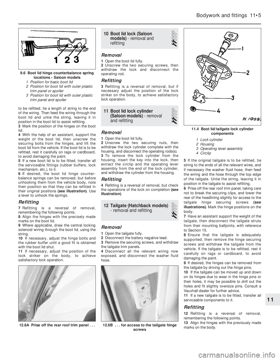
6If desired, the boot lid hinge counter-
balance springs can be removed, but before
unhooking them from the vehicle body, note
their position so that they can be refitted in
their original positions (see illustration). Use
a lever to unhook the springs.
Refitting
7Refitting is a reversal of removal,
remembering the following points.
8Align the hinges with the precisely made
marks on the boot lid.
9Where applicable, draw the central locking
solenoid wiring through the boot lid, using the
string.
10If necessary, adjust the hinge bolts and
the rubber buffer until a good fit is obtained
with the boot lid shut.
11If necessary, adjust the position of the
lock striker on the body, to achieve
satisfactory lock operation.
10Boot lid lock (Saloon
models) - removal and
refitting
2
Removal
1Open the boot lid fully.
2Unscrew the two securing screws, then
withdraw the lock and disconnect the
operating rod.
Refitting
3Refitting is a reversal of removal, but if
necessary adjust the position of the lock
striker on the body, to achieve satisfactory
lock operation.
11Boot lid lock cylinder
(Saloon models) - removal
and refitting
2
Removal
1Open the boot lid fully.
2Unscrew the two securing nuts, then
withdraw the lock cylinder complete with the
housing, and disconnect the operating rods(s).
3To remove the lock cylinder from the
housing, insert the key into the lock, then
extract the circlip and the operating lever
assembly from the end of the lock cylinder,
and withdraw the cylinder from the housing.
Refitting
4Refitting is a reversal of removal, but check
the operations of the lock on completion (see
illustration).
12Tailgate (Hatchback models)
-removal and refitting
2
Removal
1Open the tailgate fully.
2Disconnect the battery negative lead.
3Remove the securing screws, and withdraw
the tailgate trim panels.
4Disconnect all the relevant wiring now
exposed, and disconnect the washer fluid
hose.5If the original tailgate is to be refitted, tie
string to the ends of all the relevant wires, and
if necessary the washer fluid hose, then feed
the wiring and the hose through the top edge
of the tailgate. Untie the string, leaving it in
position in the tailgate to assist refitting.
6Prise off the rear roof trim panel, taking care
not to break the securing clips, and lower the
rear of the headlining slightly for access to the
tailgate hinge securing screws (see
illustrations). Mark the hinge positions on the
body.
7Have an assistant support the weight of the
tailgate, then disconnect the tailgate struts
from their mounting balljoints, with reference
to Section 15.
8Ensure that the tailgate is adequately
supported, then remove the hinge securing
screws and withdraw the tailgate from the
vehicle. If the tailgate is to be refitted, rest it
carefully on rags or cardboard, to avoid
damaging the paint.
9If desired, the hinges can be removed from
the tailgate by driving out the hinge pins.
10If the tailgate can be moved up and down
on its hinges due to wear in the hinge pins or
their holes, it may be possible to drill out the
holes and fit slightly oversize pins. Consult a
Vauxhall dealer for further advice.
11If a new tailgate is to be fitted, transfer all
serviceable components to it.
Refitting
12Refitting is a reversal of removal,
remembering the following points.
13Align the hinges with the previously made
marks on the body.
Bodywork and fittings 11•5
12.6B . . . for access to the tailgate hinge
screws12.6A Prise off the rear roof trim panel . . .
11.4 Boot lid/tailgate lock cylinder
components
1 Lock cylinder
2 Housing
3 Operating lever assembly
4 Circlip
9.6 Boot lid hinge counterbalance spring
locations - Saloon models
1 Position for basic boot lid
2 Position for boot lid with outer plastic
trim panel or spoiler
3 Position for boot lid with outer plastic
trim panel and spoiler
11
Page 128 of 525
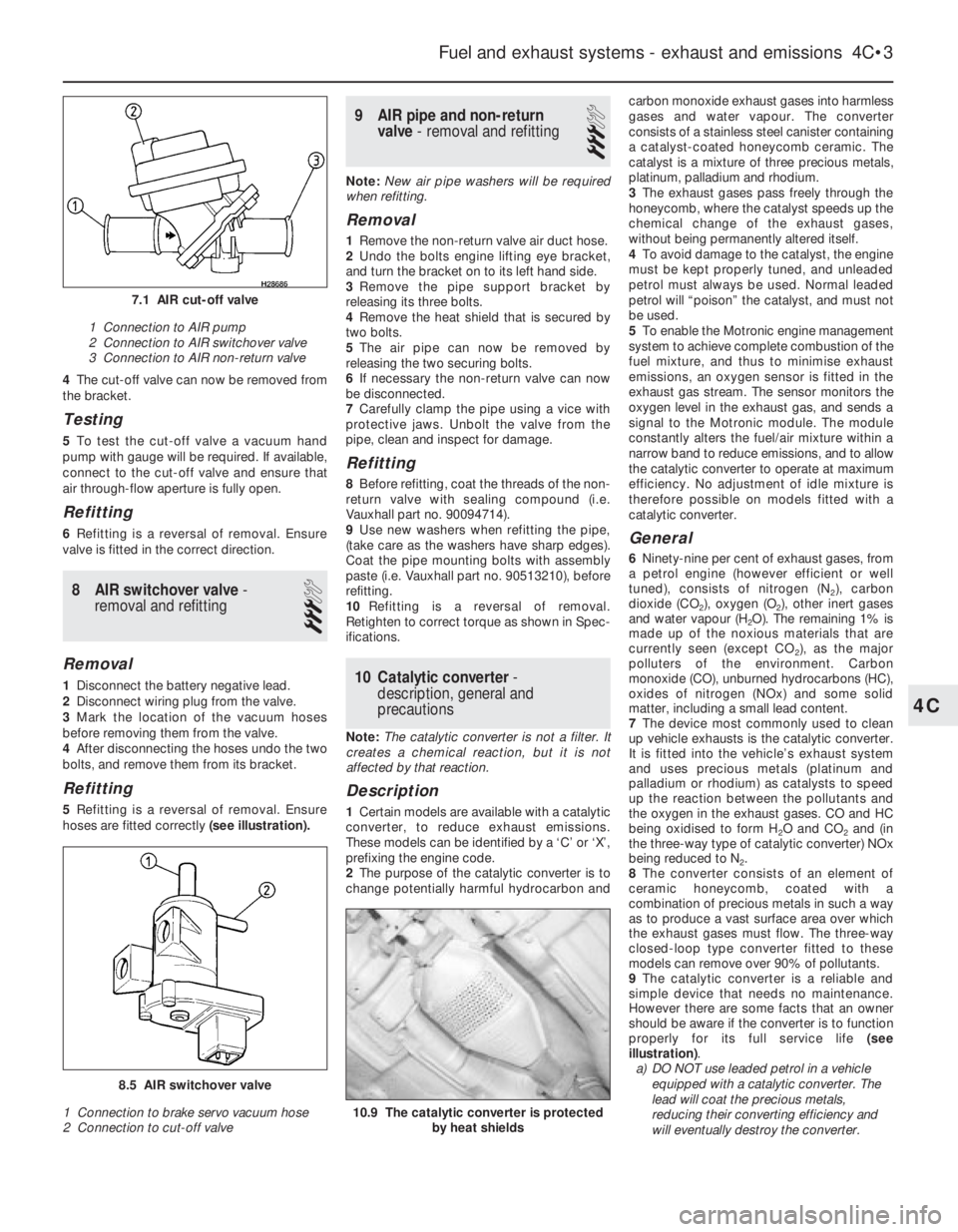
4The cut-off valve can now be removed from
the bracket.
Testing
5To test the cut-off valve a vacuum hand
pump with gauge will be required. If available,
connect to the cut-off valve and ensure that
air through-flow aperture is fully open.
Refitting
6Refitting is a reversal of removal. Ensure
valve is fitted in the correct direction.
8AIR switchover valve -
removal and refitting
3
Removal
1Disconnect the battery negative lead.
2Disconnect wiring plug from the valve.
3Mark the location of the vacuum hoses
before removing them from the valve.
4After disconnecting the hoses undo the two
bolts, and remove them from its bracket.
Refitting
5Refitting is a reversal of removal. Ensure
hoses are fitted correctly (see illustration).
9AIR pipe and non-return
valve - removal and refitting
3
Note:New air pipe washers will be required
when refitting.
Removal
1Remove the non-return valve air duct hose.
2Undo the bolts engine lifting eye bracket,
and turn the bracket on to its left hand side.
3Remove the pipe support bracket by
releasing its three bolts.
4Remove the heat shield that is secured by
two bolts.
5The air pipe can now be removed by
releasing the two securing bolts.
6If necessary the non-return valve can now
be disconnected.
7Carefully clamp the pipe using a vice with
protective jaws. Unbolt the valve from the
pipe, clean and inspect for damage.
Refitting
8Before refitting, coat the threads of the non-
return valve with sealing compound (i.e.
Vauxhall part no. 90094714).
9Use new washers when refitting the pipe,
(take care as the washers have sharp edges).
Coat the pipe mounting bolts with assembly
paste (i.e. Vauxhall part no. 90513210), before
refitting.
10Refitting is a reversal of removal.
Retighten to correct torque as shown in Spec-
ifications.
10Catalytic converter -
description, general and
precautions
Note: The catalytic converter is not a filter. It
creates a chemical reaction, but it is not
affected by that reaction.
Description
1Certain models are available with a catalytic
converter, to reduce exhaust emissions.
These models can be identified by a ‘C’ or ‘X’,
prefixing the engine code.
2The purpose of the catalytic converter is to
change potentially harmful hydrocarbon andcarbon monoxide exhaust gases into harmless
gases and water vapour. The converter
consists of a stainless steel canister containing
a catalyst-coated honeycomb ceramic. The
catalyst is a mixture of three precious metals,
platinum, palladium and rhodium.
3The exhaust gases pass freely through the
honeycomb, where the catalyst speeds up the
chemical change of the exhaust gases,
without being permanently altered itself.
4To avoid damage to the catalyst, the engine
must be kept properly tuned, and unleaded
petrol must always be used. Normal leaded
petrol will “poison” the catalyst, and must not
be used.
5To enable the Motronic engine management
system to achieve complete combustion of the
fuel mixture, and thus to minimise exhaust
emissions, an oxygen sensor is fitted in the
exhaust gas stream. The sensor monitors the
oxygen level in the exhaust gas, and sends a
signal to the Motronic module. The module
constantly alters the fuel/air mixture within a
narrow band to reduce emissions, and to allow
the catalytic converter to operate at maximum
efficiency. No adjustment of idle mixture is
therefore possible on models fitted with a
catalytic converter.
General
6Ninety-nine per cent of exhaust gases, from
a petrol engine (however efficient or well
tuned), consists of nitrogen (N
2), carbon
dioxide (CO
2), oxygen (O2), other inert gases
and water vapour (H
2O). The remaining 1% is
made up of the noxious materials that are
currently seen (except CO
2), as the major
polluters of the environment. Carbon
monoxide (CO), unburned hydrocarbons (HC),
oxides of nitrogen (NOx) and some solid
matter, including a small lead content.
7The device most commonly used to clean
up vehicle exhausts is the catalytic converter.
It is fitted into the vehicle’s exhaust system
and uses precious metals (platinum and
palladium or rhodium) as catalysts to speed
up the reaction between the pollutants and
the oxygen in the exhaust gases. CO and HC
being oxidised to form H
2O and CO2and (in
the three-way type of catalytic converter) NOx
being reduced to N
2.
8The converter consists of an element of
ceramic honeycomb, coated with a
combination of precious metals in such a way
as to produce a vast surface area over which
the exhaust gases must flow. The three-way
closed-loop type converter fitted to these
models can remove over 90% of pollutants.
9The catalytic converter is a reliable and
simple device that needs no maintenance.
However there are some facts that an owner
should be aware if the converter is to function
properly for its full service life (see
illustration).
a)DO NOT use leaded petrol in a vehicle
equipped with a catalytic converter. The
lead will coat the precious metals,
reducing their converting efficiency and
will eventually destroy the converter.
Fuel and exhaust systems - exhaust and emissions 4C•3
10.9 The catalytic converter is protected
by heat shields
8.5 AIR switchover valve
1 Connection to brake servo vacuum hose
2 Connection to cut-off valve
7.1 AIR cut-off valve
1 Connection to AIR pump
2 Connection to AIR switchover valve
3 Connection to AIR non-return valve
4C
Page 129 of 525
b)Always keep the ignition and fuel systems
well maintained according to the
manufacturers schedule (see “Routine
maintenance” and the relevant Chapter).
In particular, ensure that the air cleaner
filter element, the fuel filter and the spark
plugs are renewed at the correct intervals.
If the inlet air/fuel mixture is allowed to
become too rich due to neglect, the
unburned surplus will enter and burn in
the catalytic converter, overheating the
element and eventually destroying the
converter.
c)If the engine develops a misfire, do not
drive the vehicle at all (or at least as little
as possible) until the fault is cured. The
misfire will allow unburned fuel to enter
the converter, which will result in its
overheating, as noted above.
d)The engine control indicator (the outline
of an engine with a lightning symbol
superimposed), will light when the ignition
is switched on and the engine is started,
then it will go out. While it may light briefly
while the engine is running, it should go
out again immediately and stays unlit. If it
lights and stays on while the engine is
running, seek the advice of a Vauxhall
dealer as soon as possible. A fault has
occurred in the fuel injection/ignition
system that, apart from increasing fuel
consumption and impairing the engine’s
performance, may damage the catalytic
converter.
e)DO NOT push or tow-start the vehicle.
This will soak the catalytic converter in
unburned fuel causing it to overheat when
the engine does start see (b) above.
f)DO NOT switch off the ignition at high
engine speeds. If the ignition is switched
off at anything above idle speed,
unburned fuel will enter the (very hot)
catalytic converter, with the possible risk
of its igniting on the element and
damaging the converter.
g)DO NOT use fuel or engine oil additives.
These may contain substances harmful to
the catalytic converter.
h)DO NOT continue to use the vehicle if the
engine burns oil to the extent of leaving a
visible trail of blue smoke. The unburned
carbon deposits will clog the converter
passages and reduce its efficiency; in
severe cases the element will overheat.
i)Remember that the catalytic converter
operates at very high temperatures hence
the heat shields on the vehicle’s under-
body and the casing will become hot
enough to ignite combustible materials
that brush against it. DO NOT, therefore,
park the vehicle in dry undergrowth, over
long grass or over piles of dead leaves.
j)Remember that the catalytic converter is
FRAGlLE. Do not strike it with tools during
servicing work. Take great care when
working on the exhaust system. Ensure
that the converter is well clear of any
jacks or other lifting gear used to raise thevehicle. Do not drive the vehicle over
rough ground, road humps, etc., in such a
way as to ground the exhaust system.
k)In some cases, particularly when the
vehicle is new and/or is used for
stop/start driving, a sulphurous smell (like
that of rotten eggs) may be noticed from
the exhaust. This is common to many
catalytic converter-equipped vehicles and
seems to be due to the small amount of
sulphur found in some petrol’s reacting
with hydrogen in the exhaust to produce
hydrogen sulphide (CS) gas. While this
gas is toxic, it is not produced in sufficient
amounts to be a problem. Once the
vehicle has covered a few thousand miles
the problem should disappear. In the
meanwhile a change of driving style or of
the brand of petrol may effect a solution.
l)The catalytic converter, used on a
well-maintained and well-driven vehicle,
should last for between 50 000 and 100
000 miles. From this point on, careful
checks should be made at all specified
service intervals of the CO level to ensure
that the converter is still operating
efficiently. If the converter is no longer
effective it must be renewed.
11Carbon canister - removal
and refitting
3
Removal
1Apply the handbrake, then jack up the front
of the vehicle, and support securely on axle
stands placed under the body side members
(see “Jacking and Vehicle Support”).
2Remove the front right hand wheel and
wheel arch liner.
3Note the hose and pipe connections to the
canister, or label them, to ensure that they are
reconnected to their original unions, then
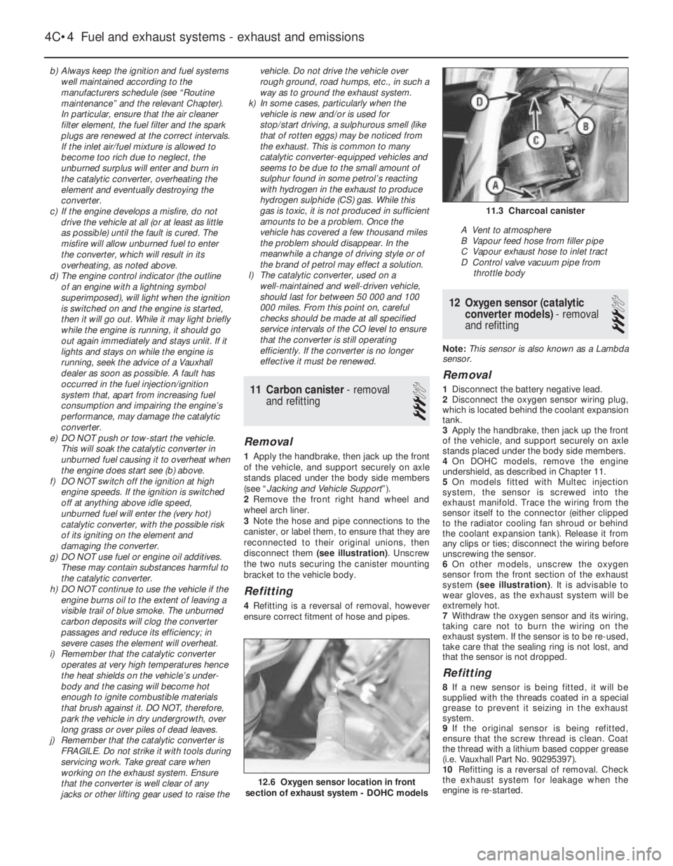
disconnect them (see illustration). Unscrew
the two nuts securing the canister mounting
bracket to the vehicle body.
Refitting
4Refitting is a reversal of removal, however
ensure correct fitment of hose and pipes.
12Oxygen sensor (catalytic
converter models) - removal
and refitting
3
Note: This sensor is also known as a Lambda
sensor.
Removal
1Disconnect the battery negative lead.
2Disconnect the oxygen sensor wiring plug,
which is located behind the coolant expansion
tank.
3Apply the handbrake, then jack up the front
of the vehicle, and support securely on axle
stands placed under the body side members.
4On DOHC models, remove the engine
undershield, as described in Chapter 11.
5On models fitted with Multec injection
system, the sensor is screwed into the
exhaust manifold. Trace the wiring from the
sensor itself to the connector (either clipped
to the radiator cooling fan shroud or behind
the coolant expansion tank). Release it from
any clips or ties; disconnect the wiring before
unscrewing the sensor.
6On other models, unscrew the oxygen
sensor from the front section of the exhaust
system (see illustration). It is advisable to
wear gloves, as the exhaust system will be
extremely hot.
7Withdraw the oxygen sensor and its wiring,
taking care not to burn the wiring on the
exhaust system. If the sensor is to be re-used,
take care that the sealing ring is not lost, and
that the sensor is not dropped.
Refitting
8If a new sensor is being fitted, it will be
supplied with the threads coated in a special
grease to prevent it seizing in the exhaust
system.
9If the original sensor is being refitted,
ensure that the screw thread is clean. Coat
the thread with a lithium based copper grease
(i.e. Vauxhall Part No. 90295397).
10Refitting is a reversal of removal. Check
the exhaust system for leakage when the
engine is re-started.
4C•4Fuel and exhaust systems - exhaust and emissions
12.6 Oxygen sensor location in front
section of exhaust system - DOHC models
11.3 Charcoal canister
A Vent to atmosphere
B Vapour feed hose from filler pipe
C Vapour exhaust hose to inlet tract
D Control valve vacuum pipe from
throttle body
Page 138 of 525
18If both brake assemblies are dismantled
at the same time, take care not to mix up the
components. Note that the left-hand and
right-hand adjuster components are marked.
The threaded rod is marked “L” or “R”, and
the other “handed” components are colour-
coded black for the left-hand side, and silver
for the right-hand side.
19Dismantle and clean the adjuster strut.
Apply a smear of silicone-based grease to the
adjuster threads.
20Examine the return springs. If they are
distorted, or if they have seen extensiveservice, renewal is advisable. Weak springs
may cause the brakes to bind.
21If a new handbrake operating lever was
not supplied with the new shoes (where
applicable), transfer the lever from the old
shoes. The lever may be secured with a pin
and circlip, or by a rivet, which will have to be
drilled out.
22If the components are to be refitted as an
assembly, assemble the new shoes, springs
and adjuster components. Expand the
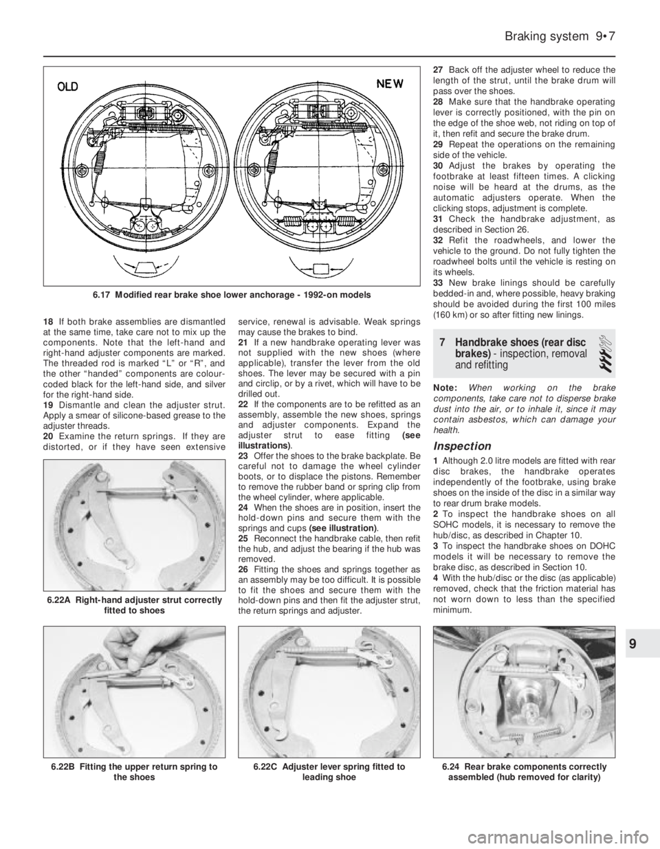
adjuster strut to ease fitting (see
illustrations).
23Offer the shoes to the brake backplate. Be
careful not to damage the wheel cylinder
boots, or to displace the pistons. Remember
to remove the rubber band or spring clip from
the wheel cylinder, where applicable.
24When the shoes are in position, insert the
hold-down pins and secure them with the
springs and cups (see illustration).
25Reconnect the handbrake cable, then refit
the hub, and adjust the bearing if the hub was
removed.
26Fitting the shoes and springs together as
an assembly may be too difficult. It is possible
to fit the shoes and secure them with the
hold-down pins and then fit the adjuster strut,
the return springs and adjuster.27Back off the adjuster wheel to reduce the
length of the strut, until the brake drum will
pass over the shoes.
28Make sure that the handbrake operating
lever is correctly positioned, with the pin on
the edge of the shoe web, not riding on top of
it, then refit and secure the brake drum.
29Repeat the operations on the remaining
side of the vehicle.
30Adjust the brakes by operating the
footbrake at least fifteen times. A clicking
noise will be heard at the drums, as the
automatic adjusters operate. When the
clicking stops, adjustment is complete.
31Check the handbrake adjustment, as
described in Section 26.
32Refit the roadwheels, and lower the
vehicle to the ground. Do not fully tighten the
roadwheel bolts until the vehicle is resting on
its wheels.
33New brake linings should be carefully
bedded-in and, where possible, heavy braking
should be avoided during the first 100 miles
(160 km) or so after fitting new linings.
7Handbrake shoes (rear disc
brakes) - inspection, removal
and refitting
3
Note: When working on the brake
components, take care not to disperse brake
dust into the air, or to inhale it, since it may
contain asbestos, which can damage your
health.
Inspection
1Although 2.0 litre models are fitted with rear
disc brakes, the handbrake operates
independently of the footbrake, using brake
shoes on the inside of the disc in a similar way
to rear drum brake models.
2To inspect the handbrake shoes on all
SOHC models, it is necessary to remove the
hub/disc, as described in Chapter 10.
3To inspect the handbrake shoes on DOHC
models it will be necessary to remove the
brake disc, as described in Section 10.
4With the hub/disc or the disc (as applicable)
removed, check that the friction material has
not worn down to less than the specified
minimum.
Braking system 9•7
6.22A Right-hand adjuster strut correctly
fitted to shoes
6.24 Rear brake components correctly
assembled (hub removed for clarity)6.22C Adjuster lever spring fitted to
leading shoe6.22B Fitting the upper return spring to
the shoes
6.17 Modified rear brake shoe lower anchorage - 1992-on models
9
Page 174 of 525
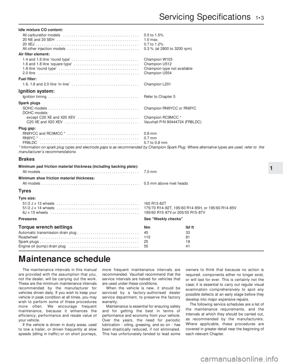
Idle mixture CO content:
All carburettor models . . . . . . . . . . . . . . . . . . . . . . . . . . . . . . . . . . . .0.5 to 1.5%
20 NE and 20 SEH . . . . . . . . . . . . . . . . . . . . . . . . . . . . . . . . . . . . . . .1.0 max.
20 XEJ . . . . . . . . . . . . . . . . . . . . . . . . . . . . . . . . . . . . . . . . . . . . . . . . .0.7 to 1.2%
All other injection models . . . . . . . . . . . . . . . . . . . . . . . . . . . . . . . . . .0.3 % (at 2800 to 3200 rpm)
Air filter element:
1.4 and 1.6 litre ‘round type’ . . . . . . . . . . . . . . . . . . . . . . . . . . . . . . . .Champion W103
1.6 and 1.8 litre ‘square type’ . . . . . . . . . . . . . . . . . . . . . . . . . . . . . . .Champion U512
1.8 litre ‘round type’ . . . . . . . . . . . . . . . . . . . . . . . . . . . . . . . . . . . . . .Champion type not available
2.0 litre . . . . . . . . . . . . . . . . . . . . . . . . . . . . . . . . . . . . . . . . . . . . . . . .Champion U554
Fuel filter:
1.6, 1.8 and 2.0 litre ‘in-line’ . . . . . . . . . . . . . . . . . . . . . . . . . . . . . . . .Champion L201
Ignition system:
Ignition timing . . . . . . . . . . . . . . . . . . . . . . . . . . . . . . . . . . . . . . . . . . .Refer to Chapter 5
Spark plugs
SOHC models . . . . . . . . . . . . . . . . . . . . . . . . . . . . . . . . . . . . . . . . . . .Champion RN9YCC or RN9YC
DOHC models:
except C20 XE and X20 XEV . . . . . . . . . . . . . . . . . . . . . . . . . . . . .Champion RC9MCC *
C20 XE and X20 XEV . . . . . . . . . . . . . . . . . . . . . . . . . . . . . . . . . . .Vauxhall P/N 90444724 (FR8LDC)
Plug gap:
RN9YCC and RC9MCC * . . . . . . . . . . . . . . . . . . . . . . . . . . . . . . . . . .0.8 mm
RN9YC * . . . . . . . . . . . . . . . . . . . . . . . . . . . . . . . . . . . . . . . . . . . . . . .0.7 mm
FR8LDC . . . . . . . . . . . . . . . . . . . . . . . . . . . . . . . . . . . . . . . . . . . . . . .0.7 to 0.8 mm
* Information on spark plug types and electrode gaps is as recommended by Champion Spark Plug. Where alternative types are used, refer to the
manufacturer’s recommendations
Brakes
Minimum pad friction material thickness (including backing plate):
All models . . . . . . . . . . . . . . . . . . . . . . . . . . . . . . . . . . . . . . . . . . . . . .7.0 mm
Minimum shoe friction material thickness:
All models . . . . . . . . . . . . . . . . . . . . . . . . . . . . . . . . . . . . . . . . . . . . . .0.5 mm above rivet heads
Tyres
Tyre size:
51/2 J x 13 wheels . . . . . . . . . . . . . . . . . . . . . . . . . . . . . . . . . . . . . . .165 R13-82T
51/2 J x 14 wheels . . . . . . . . . . . . . . . . . . . . . . . . . . . . . . . . . . . . . . .175/70 R14-82T, 195/60 R14-85H, or 195/60 R14-85V
6J x 15 wheels . . . . . . . . . . . . . . . . . . . . . . . . . . . . . . . . . . . . . . . . . .195/60 R15-87V or 205/55 R15-87V
PressuresSee “Weekly checks”
Torque wrench settingsNmlbf ft
Automatic transmission drain plug . . . . . . . . . . . . . . . . . . . . . . . . . . . . .4533
Roadwheel . . . . . . . . . . . . . . . . . . . . . . . . . . . . . . . . . . . . . . . . . . . . . . .11081
Spark plugs . . . . . . . . . . . . . . . . . . . . . . . . . . . . . . . . . . . . . . . . . . . . . . .2518
Engine oil (sump) drain plug . . . . . . . . . . . . . . . . . . . . . . . . . . . . . . . . .5541
Servicing Specifications 1•3
1
The maintenance intervals in this manual
are provided with the assumption that you,
not the dealer, will be carrying out the work.
These are the minimum maintenance intervals
recommended by the manufacturer for
vehicles driven daily. If you wish to keep your
vehicle in peak condition at all times, you may
wish to perform some of these procedures
more often. We encourage frequent
maintenance, because it enhances the
efficiency, performance and resale value of
your vehicle.
If the vehicle is driven in dusty areas, used
to tow a trailer, or driven frequently at slow
speeds (idling in traffic) or on short journeys,more frequent maintenance intervals are
recommended. Vauxhall recommend that the
service intervals are halved for vehicles that
are used under these conditions.
When the vehicle is new, it should be
serviced by a factory-authorised dealer
service department, to preserve the factory
warranty.
Maintenance is essential for ensuring safety
and for getting the best in terms of
performance and economy from your vehicle.
Over the years, the need for periodic
lubrication -oiling, greasing, and so on -has
been drastically reduced, if not eliminated.
This has unfortunately tended to lead someowners to think that because no action is
required, components either no longer exist,
or will last for ever. This is certainly not the
case; it is essential to carry out regular visual
examination comprehensively to spot any
possible defects at an early stage before they
develop into major expensive repairs.
The following service schedules are a list of
the maintenance requirements, and the
intervals at which they should be carried out,
as recommended by the manufacturers.
Where applicable, these procedures are
covered in greater detail near the beginning of
each relevant Chapter.
Maintenance schedule
Page 175 of 525
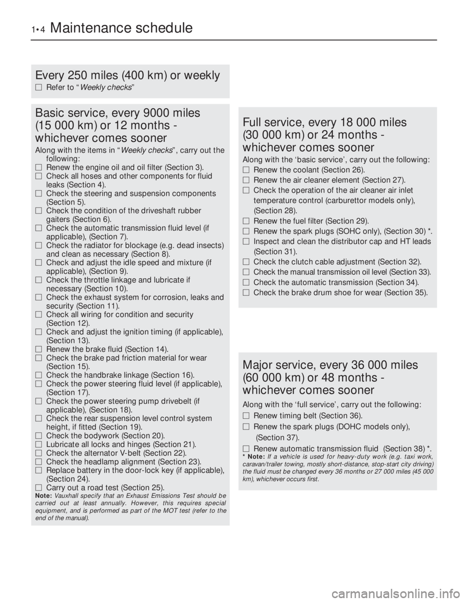
1•4Maintenance schedule
Every 250 miles (400 km) or weekly
MRefer to “Weekly checks”
Basic service, every 9000 miles
(15 000 km) or 12 months -
whichever comes sooner
Along with the items in “Weekly checks”, carry out the
following:
MRenew the engine oil and oil filter (Section 3).
MCheck all hoses and other components for fluid
leaks (Section 4).
MCheck the steering and suspension components
(Section 5).
MCheck the condition of the driveshaft rubber
gaiters (Section 6).
MCheck the automatic transmission fluid level (if
applicable), (Section 7).
MCheck the radiator for blockage (e.g. dead insects)
and clean as necessary (Section 8).
MCheck and adjust the idle speed and mixture (if
applicable), (Section 9).
MCheck the throttle linkage and lubricate if
necessary (Section 10).
MCheck the exhaust system for corrosion, leaks and
security (Section 11).
MCheck all wiring for condition and security
(Section 12).
MCheck and adjust the ignition timing (if applicable),
(Section 13).
MRenew the brake fluid (Section 14).
MCheck the brake pad friction material for wear
(Section 15).
MCheck the handbrake linkage (Section 16).
MCheck the power steering fluid level (if applicable),
(Section 17).
MCheck the power steering pump drivebelt (if
applicable), (Section 18).
MCheck the rear suspension level control system
height, if fitted (Section 19).
MCheck the bodywork (Section 20).
MLubricate all locks and hinges (Section 21).
MCheck the alternator V-belt (Section 22).
MCheck the headlamp alignment (Section 23).
MReplace battery in the door-lock key (if applicable),
(Section 24).
MCarry out a road test (Section 25).
Note: Vauxhall specify that an Exhaust Emissions Test should be
carried out at least annually. However, this requires special
equipment, and is performed as part of the MOT test (refer to the
end of the manual).
Full service, every 18 000 miles
(30 000 km) or 24 months -
whichever comes sooner
Along with the ‘basic service’, carry out the following:
MRenew the coolant (Section 26).
MRenew the air cleaner element (Section 27).
MCheck the operation of the air cleaner air inlet
temperature control (carburettor models only),
(Section 28).
MRenew the fuel filter (Section 29).
MRenew the spark plugs (SOHC only), (Section 30) *.
MInspect and clean the distributor cap and HT leads
(Section 31).
MCheck the clutch cable adjustment (Section 32).
MCheck the manual transmission oil level (Section 33).
MCheck the automatic transmission (Section 34).
MCheck the brake drum shoe for wear (Section 35).
Major service, every 36 000 miles
(60 000 km) or 48 months -
whichever comes sooner
Along with the ‘full service’, carry out the following:
MRenew timing belt (Section 36).
MRenew the spark plugs (DOHC models only),
(Section 37).
MRenew automatic transmission fluid (Section 38) *.
* Note: If a vehicle is used for heavy-duty work (e.g. taxi work,
caravan/trailer towing, mostly short-distance, stop-start city driving)
the fluid must be changed every 36 months or 27 000 miles (45 000
km), whichever occurs first.