brake light OPEL CASCADA 2014 Manual user
[x] Cancel search | Manufacturer: OPEL, Model Year: 2014, Model line: CASCADA, Model: OPEL CASCADA 2014Pages: 247, PDF Size: 7.45 MB
Page 13 of 247

In brief11
1Power windows .....................31
2 Exterior mirrors .....................28
3 Cruise control .....................151
Speed limiter ....................... 153
Forward collision alert .........154
4 Side air vents ...................... 131
5 Turn and lane-change
signals, headlight flash,
low beam and high beam,
high beam assist .................117
Exit lighting ......................... 121
Parking lights ...................... 118
Buttons for Driver
Information Centre ................94
6 Instruments .......................... 83
7 Steering wheel controls .......76
8 Driver Information Centre ...... 94
9 Windscreen wiper,
windscreen washer
system, headlight washer
system ................................... 78
10 Sport mode ........................ 149
Central locking system ..........21Hazard warning flashers ....117
Control indicator for airbag
deactivation .......................... 88
Control indicator for front
passenger seat belt .............88
Tour mode .......................... 149
11 Info-Display .......................... 98
12 Anti-theft alarm system
status LED ........................... 26
13 Centre air vents .................. 131
14 Glovebox, lockable ...............68
15 Traction Control system .....147
Electronic Stability Control . 148
Parking assist systems .......157
Lane departure warning .....170
Eco button for stop-start
system ................................. 136
16 Climate control system ........ 123
17 AUX input, USB input ..........10
18 Power outlet .......................... 8219Soft top operation switch .....34
Central window switch .........31
20 Selector lever, manual
transmission ....................... 144
Automatic transmission ......141
21 Parking brake, manual or
electric operation ................145
22 Ignition switch with
steering wheel lock ............134
23 Horn ..................................... 77
Driver airbag ........................ 60
24 Bonnet release lever ..........182
25 Storage compartment ..........69
Fuse box ............................ 199
26 Steering wheel adjustment ..76
27 Light switch ........................ 110
Headlight range
adjustment ......................... 113
Front fog lights ...................118
Rear fog light ...................... 118
Instrument illumination .......119
Page 19 of 247
![OPEL CASCADA 2014 Manual user In brief17
Automatic transmissionP=parkR=reverseN=neutralD=drive
Manual mode: move selector lever
from D to the left.
<=higher gear]=lower gear
The selector lever can only be moved
out of P when the OPEL CASCADA 2014 Manual user In brief17
Automatic transmissionP=parkR=reverseN=neutralD=drive
Manual mode: move selector lever
from D to the left.
<=higher gear]=lower gear
The selector lever can only be moved
out of P when the](/img/37/18792/w960_18792-18.png)
In brief17
Automatic transmissionP=parkR=reverseN=neutralD=drive
Manual mode: move selector lever
from D to the left.
<=higher gear]=lower gear
The selector lever can only be moved
out of P when the ignition is on and
the brake pedal is applied. To engage
P or R, press the release button.
Automatic transmission 3 141.
Starting off
Check before starting off ■ Tyre pressure and condition 3 203,
3 236.
■ Engine oil level and fluid levels 3 182.
■ All windows, mirrors, exterior lighting and number plates are free
from dirt, snow and ice and are
operational.
■ Proper position of mirrors, seats and seat belts 3 28, 3 46,
3 55.
■ Soft top must be completely opened or closed 3 34.
■ Brake function at low speed, particularly if the brakes are wet.Starting the engine
■ Turn key to position 1
■ move the steering wheel slightly to release the steering wheel lock
■ operate clutch and brake
■ automatic transmission in P or N
■ do not operate accelerator pedal
■ diesel engines: turn the key to position 2 for preheating and wait
until control indicator !
extinguishes
■ turn key to position 3 and release
Starting the engine 3 135.
Page 91 of 247
Instruments and controls89
Illuminates for approx. 60 seconds
after the ignition is switched on. The
front passenger airbag is activated.
* illuminates yellow.
The front passenger airbag is
deactivated 3 61.9 Danger
Risk of fatal injury for a child using
a child restraint system together
with activated front passenger
airbag.
Risk of fatal injury for an adult
person with deactivated front
passenger airbag.
Charging system
p illuminates red.
Illuminates when the ignition is
switched on and extinguishes shortly
after the engine starts.
Illuminates when the engine is
running
Stop, switch off engine. Vehicle
battery is not charging. Engine
cooling may be interrupted. The
brake servo unit may cease to be
effective. Seek the assistance of a
workshop.
Malfunction indicator light
Z illuminates or flashes yellow.
Illuminates when the ignition is
switched on and extinguishes shortly
after the engine starts.
Illuminates when the engine isrunning
Fault in the emission control system. The permitted emission limits may be
exceeded. Seek the assistance of a
workshop immediately.Flashes when the engine is
running
Fault that could lead to catalytic
converter damage. Ease up on the
accelerator until the flashing stops.
Seek the assistance of a workshop
immediately.
Brake and clutch system Brake and clutch fluid level
R illuminates red.
The brake and clutch fluid level is too low 3 185.9 Warning
Stop. Do not continue your
journey. Consult a workshop.
Illuminates after the ignition is
switched on if the manual parking
brake is applied 3 145.
Operate pedal
- illuminates or flashes yellow.
Page 103 of 247
Instruments and controls101
Messages in the Driver
Information Centre (DIC)
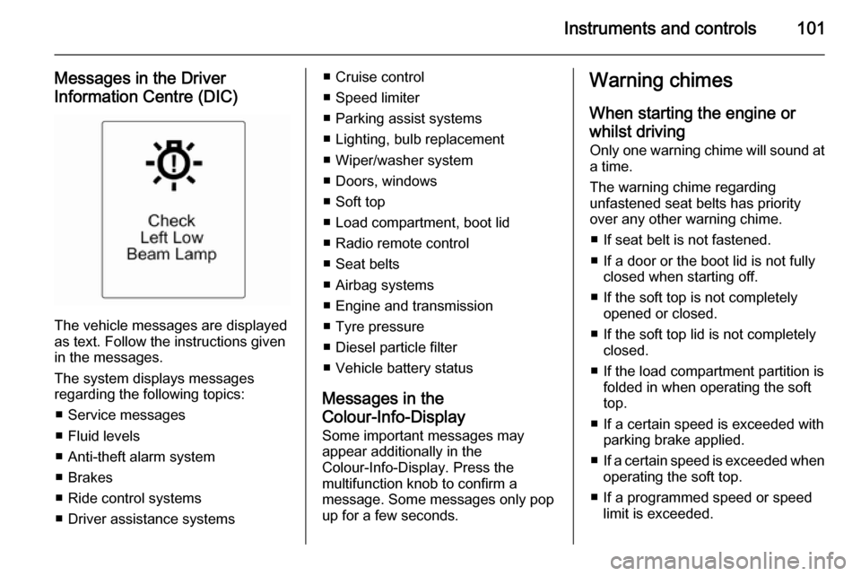
The vehicle messages are displayed
as text. Follow the instructions given
in the messages.
The system displays messages
regarding the following topics:
■ Service messages
■ Fluid levels
■ Anti-theft alarm system
■ Brakes
■ Ride control systems
■ Driver assistance systems
■ Cruise control
■ Speed limiter
■ Parking assist systems
■ Lighting, bulb replacement
■ Wiper/washer system
■ Doors, windows
■ Soft top
■ Load compartment, boot lid
■ Radio remote control
■ Seat belts
■ Airbag systems
■ Engine and transmission
■ Tyre pressure
■ Diesel particle filter
■ Vehicle battery status
Messages in the
Colour-Info-Display
Some important messages may
appear additionally in the
Colour-Info-Display. Press the
multifunction knob to confirm a
message. Some messages only pop
up for a few seconds.Warning chimes
When starting the engine or
whilst driving Only one warning chime will sound at
a time.
The warning chime regarding
unfastened seat belts has priority
over any other warning chime.
■ If seat belt is not fastened.
■ If a door or the boot lid is not fully closed when starting off.
■ If the soft top is not completely opened or closed.
■ If the soft top lid is not completely closed.
■ If the load compartment partition is folded in when operating the soft
top.
■ If a certain speed is exceeded with parking brake applied.
■ If a certain speed is exceeded when
operating the soft top.
■ If a programmed speed or speed limit is exceeded.
Page 138 of 247
136Driving and operating
Possible reasons for a non-starting
engine:
■ Clutch pedal not operated (manual transmission)
■ Brake pedal not operated or selector lever not in P or N
(automatic transmission)
■ Timeout occurred
Turbo engine warm-up Upon start-up, engine available
torque may be limited for a short time, especially when the engine
temperature is cold. The limitation is
to allow the lubrication system to fully
protect the engine.
Overrun cut-off The fuel supply is automatically cut off
during overrun, i.e. when the vehicle
is driven with a gear engaged but accelerator is released.Stop-start system
The stop-start system helps to save
fuel and to reduce the exhaust
emissions. When conditions allow, it
switches off the engine as soon as the
vehicle is at a low speed or at a
standstill, e.g. at a traffic light or in a
traffic jam. It starts the engine
automatically as soon as the clutch is depressed. A vehicle battery sensor
ensures that an Autostop is only performed if the vehicle battery is
sufficiently charged for a restart.
Activation The stop-start system is available as
soon as the engine is started, the
vehicle starts-off and the conditions
as stated below in this section are
fulfilled.Deactivation
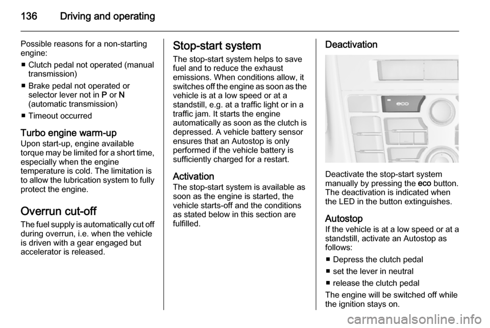
Deactivate the stop-start system
manually by pressing the eco button.
The deactivation is indicated when
the LED in the button extinguishes.
Autostop
If the vehicle is at a low speed or at a
standstill, activate an Autostop as
follows:
■ Depress the clutch pedal
■ set the lever in neutral
■ release the clutch pedal
The engine will be switched off while
the ignition stays on.
Page 147 of 247
Driving and operating145
ABS starts to regulate brake pressureas soon as a wheel shows a tendency to lock. The vehicle remains
steerable, even during hard braking.
ABS control is made apparent
through a pulse in the brake pedal
and the noise of the regulation
process.
For optimum braking, keep the brake
pedal fully depressed throughout the
braking process, despite the fact that
the pedal is pulsating. Do not reduce
the pressure on the pedal.
After starting off the system performs
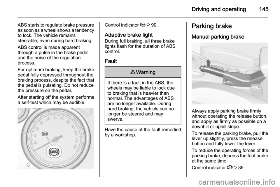
a self-test which may be audible.Control indicator u 3 90.
Adaptive brake light
During full braking, all three brake
lights flash for the duration of ABS
control.
Fault9 Warning
If there is a fault in the ABS, the
wheels may be liable to lock due
to braking that is heavier than
normal. The advantages of ABS are no longer available. During
hard braking, the vehicle can no longer be steered and may
swerve.
Have the cause of the fault remedied
by a workshop.
Parking brake
Manual parking brake
Always apply parking brake firmly
without operating the release button,
and apply as firmly as possible on a
downhill or uphill slope.
To release the parking brake, pull the lever up slightly, press the release
button and fully lower the lever.
To reduce the operating forces of the
parking brake, depress the foot brake
at the same time.
Control indicator R 3 89.
Page 173 of 247

Driving and operating171
Criteria for the detection of an
unintended lane change are:
■ no operation of turn signals
■ no brake pedal operation
■ no active accelerator operation or speeding-up
■ no active steering
If the driver is performing these
actions, no warning will be issued.
Activation
The lane departure warning system isactivated by pressing the ) button.
The illuminated LED in the button
indicates that the system is switched
on. When the control indicator ) in
the instrument cluster illuminates
green, the system is ready to operate.
The system is only operable at
vehicle speeds above 56 km/h and if
lane markings are available.
When the system recognises an
unintended lane change, the control
indicator ) changes to yellow and
flashes. Simultaneously a chime
sound is activated.
Deactivation
The system is deactivated by
pressing ) button, the LED in the
button extinguishes.
At speeds below 56 km/h the system is inoperable.
Fault
The lane departure warning system
may not operate properly when:
■ the windscreen is not clean
■ there are adverse environmental conditions like heavy rain, snow,
direct sunlight or shadows
The system can not operate when no
lane marking is detected.
Page 176 of 247

174Driving and operating
Fuel filler cap
Only use genuine fuel filler caps.
Diesel-engined vehicles have special fuel filler caps.
Fuel consumption - CO 2-
Emissions
The fuel consumption (combined) is
within a range of 7.2 to 5.2 l/100 km.
The CO 2 emission (combined) is
within a range of 169 to 138 g/km.
For the values specific to your
vehicle, refer to the EEC Certificate of Conformity provided with your vehicle
or other national registration
documents.
General information The official fuel consumption and
specific CO 2 emission figures quoted
relate to the EU base model with
standard equipment.
Fuel consumption data and CO 2
emission data are determined
according to regulation
R (EC) No. 715/2007 (in the latestapplicable version), taking into
consideration the vehicle weight in
running order, as specified by the
regulation.
The figures are provided only for the purpose of comparison between different vehicle variants and mustnot be taken as a guarantee for the
actual fuel consumption of a
particular vehicle. Additional
equipment may result in slightly
higher results than the stated
consumption and CO 2 figures.
Furthermore, fuel consumption is dependent on personal driving style
as well as road and traffic conditions.Trailer hitch
General information
Only use towing equipment that has
been approved for your vehicle.
Entrust retrofitting of towing
equipment to a workshop. It may be
necessary to make changes that
affect the cooling system, heat
shields or other equipment.
The bulb outage detection function for
trailer brake light cannot detect a
partial bulb outage, e.g. in case of 4 x
5 Watt bulbs, the function only detects lamp outage when only a single
5 Watt lamp remains or none remain.
Fitting of towing equipment could
cover the opening of the towing eye.
If this is the case use the coupling ball
bar for towing. Always keep the
coupling ball bar in the vehicle.
Page 177 of 247

Driving and operating175Driving characteristics and
towing tips Before attaching a trailer, lubricate
the coupling ball. However, do not do
so if a stabiliser, which acts on the coupling ball, is being used to reduce snaking movements.
For trailers with low driving stability
and caravan trailers with a permitted
gross vehicle weight of more than
1400 kg the use of a stabiliser is
strongly recommended when driving
above 80 km/h.
If the trailer starts snaking, drive more
slowly, do not attempt to correct the
steering and brake sharply if
necessary.
When driving downhill, drive in the
same gear as if driving uphill and
drive at a similar speed.
Adjust tyre pressure to the value
specified for full load 3 236.Trailer towing
Trailer loads
The permissible trailer loads are
vehicle and engine-dependent
maximum values which must not be
exceeded. The actual trailer load is
the difference between the actual
gross weight of the trailer and the
actual coupling socket load with the
trailer coupled.
The permissible trailer loads are
specified in the vehicle documents. In general, they are valid for gradients
up to max. 12 %.
The permitted trailer load applies up to the specified incline and up to an
altitude of 1000 metres above sea
level. Since engine power decreases
as altitude increases due to the air
becoming thinner, therefore reducing
climbing ability, the permissible gross
train weight also decreases by 10 %
for every 1000 metres of additional
altitude. The gross train weight does
not have to be reduced when driving
on roads with slight inclines (less than
8 %, e.g. motorways).The permissible gross train weight
must not be exceeded. This weight is
specified on the identification plate
3 226.
Vertical coupling load
The vertical coupling load is the load
exerted by the trailer on the coupling
ball. It can be varied by changing the
weight distribution when loading the
trailer.
The maximum permissible vertical
coupling load (75 kg) is specified on
the towing equipment identification
plate and in the vehicle documents.
Always aim for the maximum load,
especially in the case of heavy
trailers. The vertical coupling load
should never fall below 25 kg.
Page 194 of 247
192Vehicle care
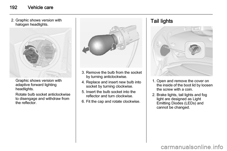
2. Graphic shows version withhalogen headlights.
Graphic shows version with
adaptive forward lighting
headlights.
Rotate bulb socket anticlockwise
to disengage and withdraw from
the reflector.
3. Remove the bulb from the socket by turning anticlockwise.
4. Replace and insert new bulb into socket by turning clockwise.
5. Insert the bulb socket into the reflector and turn clockwise.
6. Fit the cap and rotate clockwise.
Tail lights
1. Open and remove the cover on the inside of the boot lid by loosen
the screw with a coin.
2. Brake lights, tail lights and fog light are designed as Light
Emitting Diodes (LEDs) and
cannot be changed.