tyre pressure OPEL CASCADA 2014 Owner's Manual
[x] Cancel search | Manufacturer: OPEL, Model Year: 2014, Model line: CASCADA, Model: OPEL CASCADA 2014Pages: 247, PDF Size: 7.45 MB
Page 19 of 247
![OPEL CASCADA 2014 Owners Manual In brief17
Automatic transmissionP=parkR=reverseN=neutralD=drive
Manual mode: move selector lever
from D to the left.
<=higher gear]=lower gear
The selector lever can only be moved
out of P when the OPEL CASCADA 2014 Owners Manual In brief17
Automatic transmissionP=parkR=reverseN=neutralD=drive
Manual mode: move selector lever
from D to the left.
<=higher gear]=lower gear
The selector lever can only be moved
out of P when the](/img/37/18792/w960_18792-18.png)
In brief17
Automatic transmissionP=parkR=reverseN=neutralD=drive
Manual mode: move selector lever
from D to the left.
<=higher gear]=lower gear
The selector lever can only be moved
out of P when the ignition is on and
the brake pedal is applied. To engage
P or R, press the release button.
Automatic transmission 3 141.
Starting off
Check before starting off ■ Tyre pressure and condition 3 203,
3 236.
■ Engine oil level and fluid levels 3 182.
■ All windows, mirrors, exterior lighting and number plates are free
from dirt, snow and ice and are
operational.
■ Proper position of mirrors, seats and seat belts 3 28, 3 46,
3 55.
■ Soft top must be completely opened or closed 3 34.
■ Brake function at low speed, particularly if the brakes are wet.Starting the engine
■ Turn key to position 1
■ move the steering wheel slightly to release the steering wheel lock
■ operate clutch and brake
■ automatic transmission in P or N
■ do not operate accelerator pedal
■ diesel engines: turn the key to position 2 for preheating and wait
until control indicator !
extinguishes
■ turn key to position 3 and release
Starting the engine 3 135.
Page 94 of 247
92Instruments and controls
The diesel particle filter requires
cleaning.
Continue driving until %
extinguishes. If possible, do not allow engine speed to drop below
2000 rpm.
Illuminates
The diesel particle filter is full. Start cleaning process as soon as
possible.
Flashes The maximum filling level of the filter
is reached. Start cleaning process
immediately to avoid damage to the
engine.
Diesel particle filter 3 139, Stop-start
system 3 136.
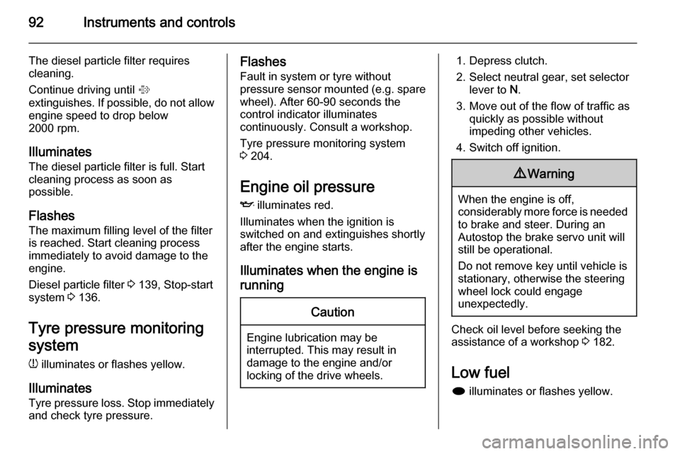
Tyre pressure monitoring system
w illuminates or flashes yellow.
Illuminates
Tyre pressure loss. Stop immediately
and check tyre pressure.Flashes
Fault in system or tyre withoutpressure sensor mounted (e.g. spare
wheel). After 60-90 seconds the
control indicator illuminates
continuously. Consult a workshop.
Tyre pressure monitoring system
3 204.
Engine oil pressure
I illuminates red.
Illuminates when the ignition is
switched on and extinguishes shortly
after the engine starts.
Illuminates when the engine is runningCaution
Engine lubrication may be
interrupted. This may result in
damage to the engine and/or
locking of the drive wheels.
1. Depress clutch.
2. Select neutral gear, set selector lever to N.
3. Move out of the flow of traffic as quickly as possible without
impeding other vehicles.
4. Switch off ignition.9 Warning
When the engine is off,
considerably more force is needed
to brake and steer. During an
Autostop the brake servo unit will still be operational.
Do not remove key until vehicle is stationary, otherwise the steeringwheel lock could engage
unexpectedly.
Check oil level before seeking the
assistance of a workshop 3 182.
Low fuel
i illuminates or flashes yellow.
Page 97 of 247
Instruments and controls95
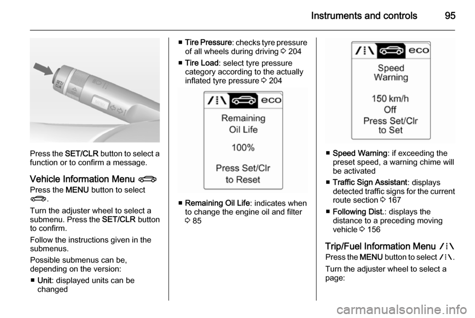
Press the SET/CLR button to select a
function or to confirm a message.
Vehicle Information Menu X
Press the MENU button to select
X .
Turn the adjuster wheel to select a
submenu. Press the SET/CLR button
to confirm.
Follow the instructions given in the
submenus.
Possible submenus can be,
depending on the version:
■ Unit : displayed units can be
changed
■ Tire Pressure : checks tyre pressure
of all wheels during driving 3 204
■ Tire Load : select tyre pressure
category according to the actually
inflated tyre pressure 3 204
■ Remaining Oil Life : indicates when
to change the engine oil and filter
3 85
■ Speed Warning : if exceeding the
preset speed, a warning chime will
be activated
■ Traffic Sign Assistant : displays
detected traffic signs for the current
route section 3 167
■ Following Dist. : displays the
distance to a preceding moving
vehicle 3 156
Trip/Fuel Information Menu W
Press the MENU button to select W.
Turn the adjuster wheel to select a
page:
Page 103 of 247
Instruments and controls101
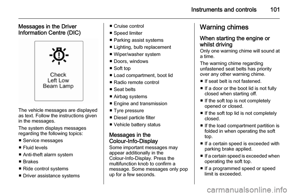
Messages in the Driver
Information Centre (DIC)
The vehicle messages are displayed
as text. Follow the instructions given
in the messages.
The system displays messages
regarding the following topics:
■ Service messages
■ Fluid levels
■ Anti-theft alarm system
■ Brakes
■ Ride control systems
■ Driver assistance systems
■ Cruise control
■ Speed limiter
■ Parking assist systems
■ Lighting, bulb replacement
■ Wiper/washer system
■ Doors, windows
■ Soft top
■ Load compartment, boot lid
■ Radio remote control
■ Seat belts
■ Airbag systems
■ Engine and transmission
■ Tyre pressure
■ Diesel particle filter
■ Vehicle battery status
Messages in the
Colour-Info-Display
Some important messages may
appear additionally in the
Colour-Info-Display. Press the
multifunction knob to confirm a
message. Some messages only pop
up for a few seconds.Warning chimes
When starting the engine or
whilst driving Only one warning chime will sound at
a time.
The warning chime regarding
unfastened seat belts has priority
over any other warning chime.
■ If seat belt is not fastened.
■ If a door or the boot lid is not fully closed when starting off.
■ If the soft top is not completely opened or closed.
■ If the soft top lid is not completely closed.
■ If the load compartment partition is folded in when operating the soft
top.
■ If a certain speed is exceeded with parking brake applied.
■ If a certain speed is exceeded when
operating the soft top.
■ If a programmed speed or speed limit is exceeded.
Page 149 of 247

Driving and operating147
Control indicator m flashes: electric
parking brake is not fully applied or released. When continuously
flashing, release electric parking
brake and retry applying.
Brake assist If the brake pedal is depressed
quickly and forcefully, maximum
brake force is automatically applied
(full braking).
Maintain steady pressure on the
brake pedal for as long as full braking
is required. Maximum brake force is
automatically reduced when the
brake pedal is released.
Hill start assist The system helps prevent unintendedmovement when driving away on
inclines.
When releasing the foot brake after
stopping on an incline, the brakes
remain on for a further two seconds.
The brakes release automatically as
soon as the vehicle begins to
accelerate.The hill start assist is not active during
an Autostop.Ride control systems
Traction Control system
The Traction Control system (TC) is a
component of the Electronic Stability
Control (ESC) 3 148.
TC improves driving stability when
necessary, regardless of the type of
road surface or tyre grip, by
preventing the drive wheels from
spinning.
As soon as the drive wheels starts to spin, engine output is reduced and
the wheel spinning the most is braked
individually. This considerably
improves the driving stability of the
vehicle on slippery road surfaces.
Page 177 of 247

Driving and operating175Driving characteristics and
towing tips Before attaching a trailer, lubricate
the coupling ball. However, do not do
so if a stabiliser, which acts on the coupling ball, is being used to reduce snaking movements.
For trailers with low driving stability
and caravan trailers with a permitted
gross vehicle weight of more than
1400 kg the use of a stabiliser is
strongly recommended when driving
above 80 km/h.
If the trailer starts snaking, drive more
slowly, do not attempt to correct the
steering and brake sharply if
necessary.
When driving downhill, drive in the
same gear as if driving uphill and
drive at a similar speed.
Adjust tyre pressure to the value
specified for full load 3 236.Trailer towing
Trailer loads
The permissible trailer loads are
vehicle and engine-dependent
maximum values which must not be
exceeded. The actual trailer load is
the difference between the actual
gross weight of the trailer and the
actual coupling socket load with the
trailer coupled.
The permissible trailer loads are
specified in the vehicle documents. In general, they are valid for gradients
up to max. 12 %.
The permitted trailer load applies up to the specified incline and up to an
altitude of 1000 metres above sea
level. Since engine power decreases
as altitude increases due to the air
becoming thinner, therefore reducing
climbing ability, the permissible gross
train weight also decreases by 10 %
for every 1000 metres of additional
altitude. The gross train weight does
not have to be reduced when driving
on roads with slight inclines (less than
8 %, e.g. motorways).The permissible gross train weight
must not be exceeded. This weight is
specified on the identification plate
3 226.
Vertical coupling load
The vertical coupling load is the load
exerted by the trailer on the coupling
ball. It can be varied by changing the
weight distribution when loading the
trailer.
The maximum permissible vertical
coupling load (75 kg) is specified on
the towing equipment identification
plate and in the vehicle documents.
Always aim for the maximum load,
especially in the case of heavy
trailers. The vertical coupling load
should never fall below 25 kg.
Page 182 of 247
180Vehicle careVehicle careGeneral Information...................180
Vehicle checks ........................... 181
Bulb replacement .......................188
Electrical system ........................196
Vehicle tools .............................. 201
Wheels and tyres .......................202
Jump starting ............................. 216
Towing ....................................... 218
Appearance care .......................220General Information
Accessories and vehicle
modifications
We recommend the use of genuine parts and accessories and factory
approved parts specific for your
vehicle type. We cannot assess or
guarantee reliability of other products
- even if they have a regulatory or
otherwise granted approval.
Do not make any modifications to the electrical system, e.g. changes of
electronic control units (chip tuning).Caution
When transporting the vehicle on
a train or on a recovery vehicle, the
mud flaps might be damaged.
Vehicle storage
Storage for a long period of time
If the vehicle is to be stored for several months:
■ Wash the vehicle. Wax painted parts of the vehicle. Exterior care
3 220.
■ Have the wax in the engine compartment and underbody
checked.
■ Clean and preserve the rubber seals.
■ Fill up fuel tank completely.
■ Change the engine oil.
■ Drain the washer fluid reservoir.
■ Check the coolant antifreeze and corrosion protection.
■ Adjust tyre pressure to the value specified for full load.
■ Park the vehicle in a dry, well ventilated place. Engage first orreverse gear or set selector lever to P . Prevent the vehicle from rolling.
■ Do not apply the parking brake.
Page 183 of 247

Vehicle care181
■ Open the bonnet, close all doorsand lock the vehicle.
■ Close the soft top.
■ Cover the soft top to reduce environment influences.
■ Disconnect the clamp from the negative terminal of the vehicle
battery. Beware that all systems are
not functional, e.g. anti-theft alarm
system.
Putting back into operation
When the vehicle is to be put back into
operation:
■ Connect the clamp to the negative terminal of the vehicle battery.
Activate the electronics of the
power windows.
■ Check tyre pressure.
■ Fill up the washer fluid reservoir.
■ Check the engine oil level.
■ Check the coolant level.
■ Fit the number plate if necessary.End-of-life vehicle
recovery
Information on end-of-life vehicle
recovery centres and the recycling of
end-of-life vehicles is available on our website, where legally required. Only
entrust this work to an authorised
recycling centre.Vehicle checks
Performing work9 Warning
Only perform engine compartment
checks when the ignition is off.
The cooling fan may start
operating even if the ignition is off.
Page 205 of 247
Vehicle care203
Use tyre size 225/55 R17 only as
winter tyres.
On vehicles with Diesel engines, no
steel rims and only special, vehicle-
approved alloy wheels are permitted.
In accordance with country-specific
regulations, affix the speed sticker in
the driver's field of view.
Tyre designationsE.g. 235/55 R 17 99 V235=Tyre width, mm55=Cross-section ratio (tyre
height to tyre width), %R=Belt type: RadialRF=Type: RunFlat17=Wheel diameter, inches99=Load index e.g. 99 is
equivalent to 775 kgV=Speed code letter
Speed code letter:
Q=up to 160 km/hS=up to 180 km/hT=up to 190 km/hH=up to 210 km/hV=up to 240 km/hW=up to 270 km/hTyre pressure
Check the pressure of cold tyres at least every 14 days and before any
long journey. Do not forget the spare
wheel. This also applies to vehicles
with tyre pressure monitoring system.
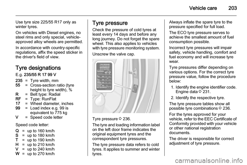
Unscrew the valve cap.
Tyre pressure 3 236.
The tyre and loading information label on the left door frame indicates the
original equipment tyres and the
correspondent tyre pressures.
The tyre pressure data refers to cold
tyres. It applies to summer and winter
tyres.
Always inflate the spare tyre to the
pressure specified for full load.
The ECO tyre pressure serves to
achieve the smallest amount of fuel
consumption possible.
Incorrect tyre pressures will impair
safety, vehicle handling, comfort and fuel economy and will increase tyre
wear.
Tyre pressures differ depending on
various options. For the correct tyre pressure value, follow the procedure
below:
1. Identify the engine identifier code.
Engine data 3 231.
2. Identify the respective tyre.
The tyre pressure tables show all possible tyre combinations 3 236.
For the tyres approved for your
vehicle, refer to the EEC Certificate of
Conformity provided with your vehicle or other national registration
documents.
The driver is responsible for correct
adjustment of tyre pressure.
Page 206 of 247

204Vehicle care9Warning
If the pressure is too low, this can
result in considerable tyre warm-
up and internal damage, leading to tread separation and even to tyre
blow-out at high speeds.
If the tyre pressure must be reduced
or increased on a vehicle with tyre
pressure monitoring system, switch
off ignition. After adjusting tyre
pressure switch on ignition and select the relevant setting on the page Tyre
load on the Driver Information Centre,
3 94.
Tyre pressure monitoring
system The tyre pressure monitoring system
checks the pressure of all four wheels once a minute when vehicle speed
exceeds a certain limit.
Caution
Tyre pressure monitoring system
warns just about low tyre pressure condition and does not replace
regular tyre maintenance by the
driver.
All wheels must be equipped with
pressure sensors and the tyres must
have the prescribed pressure.
The current tyre pressures can be
shown in the Vehicle Information
Menu in the Driver Information
Centre.
The menu can be selected by the buttons on the turn signal lever.
Press the MENU button to select the
Vehicle Information Menu X.