lock OPEL CASCADA 2017 Manual user
[x] Cancel search | Manufacturer: OPEL, Model Year: 2017, Model line: CASCADA, Model: OPEL CASCADA 2017Pages: 263, PDF Size: 7.76 MB
Page 202 of 263

200Vehicle careFront turn signal lights
1. Rotate cap (1) anticlockwise andremove it.
2. The illustration shows versionwith halogen headlights.
The illustration shows version
with adaptive forward lighting
headlights.
Rotate bulb socket anticlockwise
to disengage and withdraw from
the reflector.
3. Remove the bulb from the socket by turning anticlockwise.
4. Replace and insert new bulb into socket by turning clockwise.
5. Insert the bulb socket into the reflector and turn clockwise.
6. Fit the cap and rotate clockwise.
Page 203 of 263

Vehicle care201Tail lights
1. Open and remove the cover onthe inside of the boot lid by loosen
the screw with a coin.
2. Brake lights, tail lights and fog light are designed as Light
Emitting Diodes (LEDs) and
cannot be changed.
Remove bulb holder by turning
anticlockwise.
Turn signal lights ( 1)
Reversing lights ( 2)
3. Remove and replace bulb
4. Insert bulb holder into tail light
assembly and turn clockwise.
5. Close the cover by inserting thefastener clips first. Lock the cover
by turning the screw clockwise
with a coin.
Additional lights in the boot lid
frame
1. Open the boot lid.
Page 204 of 263

202Vehicle care
2. Release cover in side trim paneland remove.
3. Remove bulb holder by turninganticlockwise.
Turn signal lights ( 1)
Tail lights ( 2)
4. Remove and replace bulb.
5. Insert the bulb holder into housing
and turn clockwise.
6. Attach the side trim cover.
Side turn signal lights
To replace bulb, remove lamp
housing:
1. Slide lamp to its left side and remove with its right end.
Page 205 of 263

Vehicle care203
2. Turn bulb holder anticlockwiseand remove from housing.
3. Pull bulb from bulb holder andreplace it.
4. Insert bulb holder and turnclockwise.
5. Insert left end of the lamp, slide to
the left and insert right end.
Number plate light
1. Insert screwdriver in recess of the
cover, press to the side and
release spring.
2. Remove lamp downwards, taking care not to pull on the cable.
3. Remove bulb holder from lamphousing by turning anticlockwise.
4. Pull bulb from bulb holder and replace it.
Page 206 of 263

204Vehicle care5. Insert bulb holder into lamphousing and turn clockwise.
6. Insert lamp into bumper and let engage.
Interior lights Courtesy light, reading lights
Have bulbs replaced by a workshop.
Load compartment light
Have bulbs replaced by a workshop.
Instrument panel illumination
Have bulbs replaced by a workshop.Electrical system
Fuses Data on the replacement fuse mustmatch the data on the defective fuse.
There are three fuse boxes in the vehicle:
● In the front left of the engine compartment,
● In left-hand drive vehicles, in the interior behind the storage
compartment, or, in right-hand
drive vehicles, behind the
glovebox,
● Behind a cover on the left side of
the load compartment.
Before replacing a fuse, turn off the
respective switch and the ignition.
A blown fuse can be recognized by its melted wire. Do not replace the fuse
until the cause of the fault has been
remedied.
Some functions are protected by
several fuses.
Fuses may also be inserted without existence of a function.
Fuse extractor
A fuse extractor may be located in the
fuse box in the engine compartment.
Page 209 of 263

Vehicle care207No.Circuit51–52Auxiliary heater, diesel engine53Transmission control module,
Engine control module54Vacuum pump, instrument
panel cluster, heating ventila‐
tion, air conditioning system
After having changed defective fuses,
close the fuse box cover and press
until it engages.
If the fuse box cover is not closed
correctly, malfunctions may occur.
Instrument panel fuse box
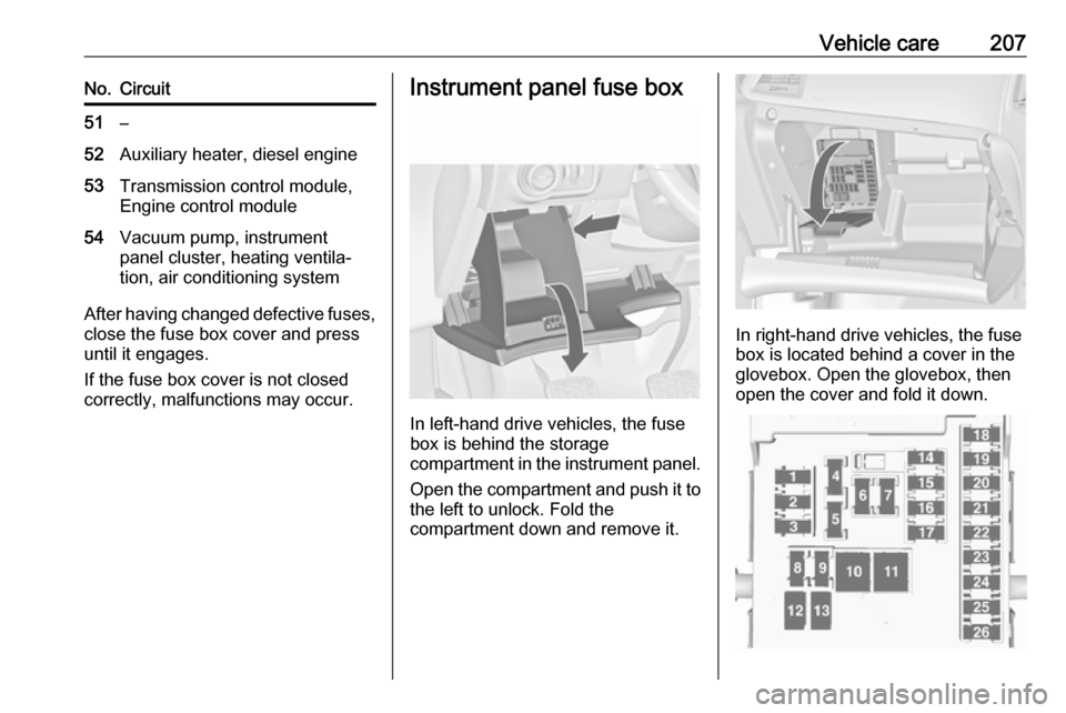
In left-hand drive vehicles, the fuse
box is behind the storage
compartment in the instrument panel.
Open the compartment and push it to the left to unlock. Fold the
compartment down and remove it.
In right-hand drive vehicles, the fuse
box is located behind a cover in the
glovebox. Open the glovebox, then
open the cover and fold it down.
Page 210 of 263

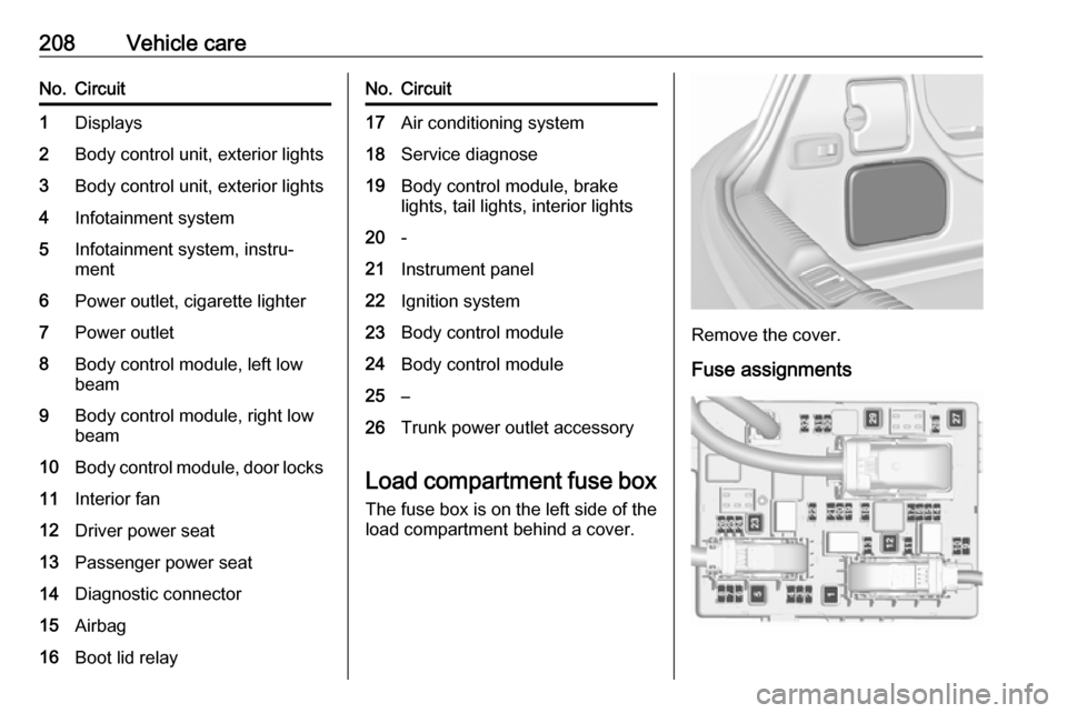
208Vehicle careNo.Circuit1Displays2Body control unit, exterior lights3Body control unit, exterior lights4Infotainment system5Infotainment system, instru‐
ment6Power outlet, cigarette lighter7Power outlet8Body control module, left low
beam9Body control module, right low
beam10Body control module, door locks11Interior fan12Driver power seat13Passenger power seat14Diagnostic connector15Airbag16Boot lid relayNo.Circuit17Air conditioning system18Service diagnose19Body control module, brake
lights, tail lights, interior lights20-21Instrument panel22Ignition system23Body control module24Body control module25–26Trunk power outlet accessory
Load compartment fuse box
The fuse box is on the left side of the
load compartment behind a cover.
Remove the cover.
Fuse assignments
Page 219 of 263

Vehicle care2179Warning
Use of unsuitable tyres or wheels
may lead to accidents and will
invalidate the vehicle type
approval.
Wheel covers
Wheel covers and tyres that are
factory approved for the respective
vehicle and comply with all of the
relevant wheel and tyre combination
requirements must be used.
If the wheel covers and tyres used are
not factory approved, the tyres must
not have a rim protection ridge.
Wheel covers must not impair brake
cooling.
9 Warning
Use of unsuitable tyres or wheel
covers could lead to sudden
pressure loss and thereby
accidents.
Vehicles with steel wheels: When
using locking wheel nuts, do not
attach wheel covers.
Tyre chains
Use tyre chains only on front wheels.
Always use fine mesh chains that add no more than 10 mm to the tyre tread
and the inboard sides (including chain
lock).
9 Warning
Damage may lead to tyre blowout.
Tyre chains are permitted on tyres of
sizes 225/55 R17 and 245/45 R18.
The use of tyre chains is not permitted on the temporary spare wheel.
Tyre repair kit
Minor damage to the tyre tread can be
repaired with the tyre repair kit.
Do not remove foreign bodies from
the tyres.
Tyre damage exceeding 4 mm or that
is at tyre's sidewall cannot be repaired with the tyre repair kit.9 Warning
Do not drive faster than 80 km/h.
Do not use for a lengthy period.
Steering and handling may be
affected.
If you have a flat tyre:
Apply the parking brake and engage
first gear, reverse gear or P.
Page 224 of 263

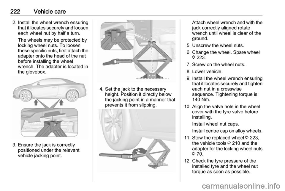
222Vehicle care2. Install the wheel wrench ensuringthat it locates securely and loosen
each wheel nut by half a turn.
The wheels may be protected by
locking wheel nuts. To loosen
these specific nuts, first attach the adapter onto the head of the nut
before installing the wheel
wrench. The adapter is located in
the glovebox.
3. Ensure the jack is correctly positioned under the relevant
vehicle jacking point.
4. Set the jack to the necessary height. Position it directly below
the jacking point in a manner that
prevents it from slipping.
Attach wheel wrench and with the
jack correctly aligned rotate
wrench until wheel is clear of the
ground.
5. Unscrew the wheel nuts. 6. Change the wheel. Spare wheel 3 223.
7. Screw on the wheel nuts.
8. Lower vehicle.
9. Install the wheel wrench ensuring that it locates securely and tighten
each nut in a crosswise
sequence. Tightening torque is
140 Nm.
10. Align the valve hole in the wheel cover with the tyre valve before
installing.
Install wheel nut caps.
Install centre cap on alloy wheels.
11. Stow the replaced wheel 3 223,
the vehicle tools 3 210 and the
adapter for the locking wheel nuts
3 70.
12. Check the tyre pressure of the installed tyre and the wheel nut
torque as soon as possible.
Page 227 of 263

Vehicle care225
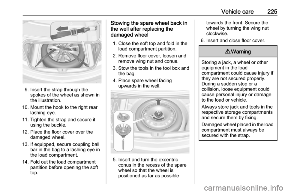
9. Insert the strap through thespokes of the wheel as shown in
the illustration.
10. Mount the hook to the right rear lashing eye.
11. Tighten the strap and secure it using the buckle.
12. Place the floor cover over the damaged wheel.
13. If equipped, secure coupling ball bar in the bag to a lashing eye in
the load compartment.
14. Fold out the load compartment partition before opening the soft
top.
Stowing the spare wheel back in
the well after replacing the
damaged wheel
1. Close the soft top and fold in the load compartment partition.
2. Remove floor cover, loosen and remove wing nut and conus.
3. Stow the tools in the tool box and the bag.
4. Place spare wheel facing upwards in the well.
5. Insert and turn the excentric conus in the recess of the spare
wheel so that the wheel is
positioned as far as possible
towards the front. Secure the
wheel by turning the wing nut
clockwise.
6. Insert and close floor cover.9 Warning
Storing a jack, a wheel or other
equipment in the load
compartment could cause injury if they are not secured properly.
During a sudden stop or a
collision, loose equipment could cause personal injury or damage
to the load or vehicle.
Always store jack and tools in the
respective storage compartments
and secure them by fixing.
Damaged wheel placed in the load compartment must always be
secured with the strap.