glove box OPEL CASCADA 2017 Manual user
[x] Cancel search | Manufacturer: OPEL, Model Year: 2017, Model line: CASCADA, Model: OPEL CASCADA 2017Pages: 263, PDF Size: 7.76 MB
Page 13 of 263

In brief111Power windows .....................33
2 Exterior mirrors .....................31
3 Cruise control .....................158
Speed limiter ....................... 160
Forward collision alert .........161
4 Side air vents ...................... 134
5 Turn and lane-change
signals, headlight flash,
low beam and high beam,
high beam assist .................121
Exit lighting ......................... 124
Parking lights ...................... 122
Buttons for Driver
Information Centre ................95
6 Instruments .......................... 85
7 Steering wheel controls .......79
8 Driver Information Centre ...... 95
9 Windscreen wiper,
windscreen washer
system, headlight washer
system ................................... 80
10 Sport mode ........................ 156
Central locking system ..........23Hazard warning flashers ....120
Control indicator for airbag deactivation .......................... 90
Control indicator for front
passenger seat belt .............89
Tour mode .......................... 156
11 Info-Display ........................ 100
12 Anti-theft alarm system
status LED ........................... 28
13 Centre air vents .................. 134
14 Glovebox, lockable ...............70
15 Traction Control system
(TC) ..................................... 154
Electronic Stability Control (ESC) .................................. 155
Parking assist systems .......164
Lane departure warning .....178
Eco button for stop-start
system ................................. 139
16 Climate control system ........ 126
17 AUX input, USB input ..........10
18 Power outlet .......................... 8419Soft top operation switch .....36
Central window switch .........33
20 Selector lever, transmission
21 Parking brake, manual or
electric operation ................152
22 Ignition switch with
steering wheel lock ............138
23 Horn ..................................... 80
Driver airbag ........................ 62
24 Bonnet release lever ..........190
25 Storage compartment ..........71
Fuse box ............................ 207
26 Steering wheel adjustment ..79
27 Light switch ........................ 113
Rear fog light ...................... 121
Instrument illumination .......122
Headlight range
adjustment ......................... 116
Front fog lights ...................121
Page 15 of 263

In brief131Power windows .....................33
2 Exterior mirrors .....................31
3 Cruise control .....................158
Speed limiter ....................... 160
Forward collision alert .........161
4 Side air vents ...................... 134
5 Turn and lane-change
signals, headlight flash,
low beam and high beam,
high beam assist .................121
Exit lighting ......................... 124
Parking lights ...................... 122
Buttons for Driver
Information Centre ................95
6 Instruments .......................... 85
7 Steering wheel controls .......79
8 Driver Information Centre ...... 95
9 Windscreen wiper,
windscreen washer
system, headlight washer
system ................................... 80
10 Sport mode ........................ 156
Central locking system ..........23Hazard warning flashers ....120
Control indicator for airbag deactivation .......................... 90
Control indicator for front
passenger seat belt .............89
Tour mode .......................... 156
11 Info-Display ........................ 100
12 Anti-theft alarm system
status LED ........................... 28
13 Centre air vents .................. 134
14 Glovebox, lockable ...............70
Fuse box ............................. 207
15 Traction Control system
(TC) ..................................... 154
Electronic Stability Control (ESC) .................................. 155
Parking assist systems .......164
Lane departure warning .....178
Eco button for stop-start
system ................................. 139
16 Climate control system ........ 126
17 AUX input, USB input ..........10
18 Power outlet .......................... 8419Soft top operation switch .....36
Central window switch .........33
20 Selector lever, transmission
21 Parking brake, manual or
electric operation ................152
22 Ignition switch with
steering wheel lock ............138
23 Horn ..................................... 80
Driver airbag ........................ 62
24 Bonnet release lever ..........190
25 Storage compartment ..........71
Fuse box ............................ 207
26 Steering wheel adjustment ..79
27 Light switch ........................ 113
Rear fog light ...................... 121
Instrument illumination .......122
Headlight range
adjustment ......................... 116
Front fog lights ...................121
Page 42 of 263

40Keys, doors and windowsCaution
We strongly advise performingmanual closing of the soft top with two persons.
Manual operation of the soft top is permitted only for closing.
Read the following description
completely before starting to
operate.
Do not perform the manual closing with the vehicle parked on
downhill gradient or inclines.
Remove the large wind deflector
before starting to operate.
After closing, have the soft top
repaired by a workshop.
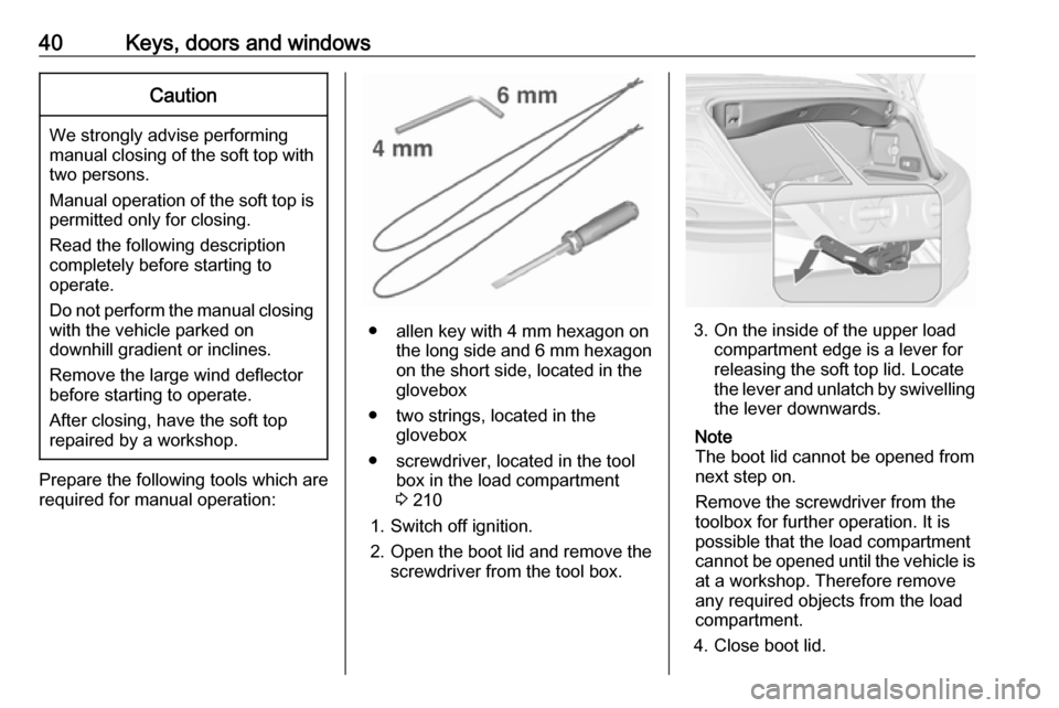
Prepare the following tools which are
required for manual operation:
● allen key with 4 mm hexagon on the long side and 6 mm hexagon
on the short side, located in the
glovebox
● two strings, located in the glovebox
● screwdriver, located in the tool box in the load compartment
3 210
1. Switch off ignition.
2. Open the boot lid and remove the
screwdriver from the tool box.3. On the inside of the upper load
compartment edge is a lever for
releasing the soft top lid. Locate
the lever and unlatch by swivelling the lever downwards.
Note
The boot lid cannot be opened from
next step on.
Remove the screwdriver from the
toolbox for further operation. It is
possible that the load compartment
cannot be opened until the vehicle is
at a workshop. Therefore remove
any required objects from the load
compartment.
4. Close boot lid.
Page 72 of 263

70StorageStorageStorage compartments................70
Glovebox ................................... 70
Cupholders ................................ 71
Front storage ............................. 71
Armrest storage .........................72
Centre console storage .............72
Load compartment .......................73
Rear storage .............................. 75
Rear floor storage cover ............75
Lashing eyes ............................. 76
Warning triangle ........................76
First aid kit ................................. 76
Loading information .....................77Storage compartments9Warning
Do not store heavy or sharp
objects in the storage
compartments. Otherwise, the
storage compartment lid could
open and vehicle occupants could be injured by objects being thrown
around in the event of hard
braking, a sudden change in
direction or an accident.
Glovebox
The glovebox features a pen holder,
a credit card holder, a coin holder and
an adapter for the locking wheel nuts.
Close glovebox whilst driving. It can
be locked with the vehicle key.
Page 74 of 263

72StorageArmrest storage
Storage under the front armrest
Press button to fold up the armrest.
The armrest must be in rearmost
position.
Centre console storage
Front console Depending on the version, a storage
compartment is located under a
cover.
Slide cover backwards.
Press button to remove the frame of
the cupholder. The frame can be
stowed in the glovebox.
A further storage compartment is
located under the intermediate shelf.
Fold up the intermediate shelf and fix it in the vertical position. The frame of
the cupholder can be reintegrated to
stow bottles.
Rear console
Pull out the drawer.
Caution
Do not use for ashes or for other
glowing items.
Page 206 of 263

204Vehicle care5. Insert bulb holder into lamphousing and turn clockwise.
6. Insert lamp into bumper and let engage.
Interior lights Courtesy light, reading lights
Have bulbs replaced by a workshop.
Load compartment light
Have bulbs replaced by a workshop.
Instrument panel illumination
Have bulbs replaced by a workshop.Electrical system
Fuses Data on the replacement fuse mustmatch the data on the defective fuse.
There are three fuse boxes in the vehicle:
● In the front left of the engine compartment,
● In left-hand drive vehicles, in the interior behind the storage
compartment, or, in right-hand
drive vehicles, behind the
glovebox,
● Behind a cover on the left side of
the load compartment.
Before replacing a fuse, turn off the
respective switch and the ignition.
A blown fuse can be recognized by its melted wire. Do not replace the fuse
until the cause of the fault has been
remedied.
Some functions are protected by
several fuses.
Fuses may also be inserted without existence of a function.
Fuse extractor
A fuse extractor may be located in the
fuse box in the engine compartment.
Page 209 of 263

Vehicle care207No.Circuit51–52Auxiliary heater, diesel engine53Transmission control module,
Engine control module54Vacuum pump, instrument
panel cluster, heating ventila‐
tion, air conditioning system
After having changed defective fuses,
close the fuse box cover and press
until it engages.
If the fuse box cover is not closed
correctly, malfunctions may occur.
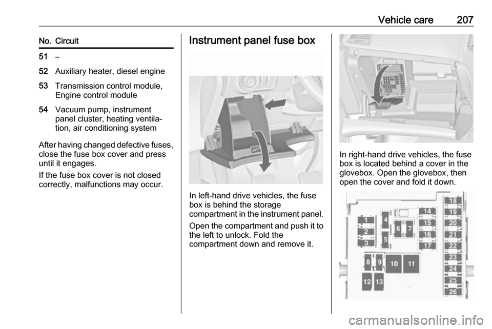
Instrument panel fuse box
In left-hand drive vehicles, the fuse
box is behind the storage
compartment in the instrument panel.
Open the compartment and push it to the left to unlock. Fold the
compartment down and remove it.
In right-hand drive vehicles, the fuse
box is located behind a cover in the
glovebox. Open the glovebox, then
open the cover and fold it down.
Page 224 of 263

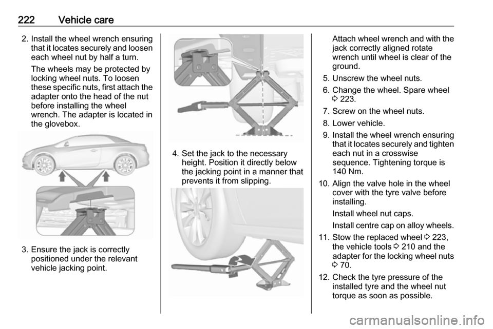
222Vehicle care2. Install the wheel wrench ensuringthat it locates securely and loosen
each wheel nut by half a turn.
The wheels may be protected by
locking wheel nuts. To loosen
these specific nuts, first attach the adapter onto the head of the nut
before installing the wheel
wrench. The adapter is located in
the glovebox.
3. Ensure the jack is correctly positioned under the relevant
vehicle jacking point.
4. Set the jack to the necessary height. Position it directly below
the jacking point in a manner that
prevents it from slipping.
Attach wheel wrench and with the
jack correctly aligned rotate
wrench until wheel is clear of the
ground.
5. Unscrew the wheel nuts. 6. Change the wheel. Spare wheel 3 223.
7. Screw on the wheel nuts.
8. Lower vehicle.
9. Install the wheel wrench ensuring that it locates securely and tighten
each nut in a crosswise
sequence. Tightening torque is
140 Nm.
10. Align the valve hole in the wheel cover with the tyre valve before
installing.
Install wheel nut caps.
Install centre cap on alloy wheels.
11. Stow the replaced wheel 3 223,
the vehicle tools 3 210 and the
adapter for the locking wheel nuts
3 70.
12. Check the tyre pressure of the installed tyre and the wheel nut
torque as soon as possible.
Page 259 of 263

257Clock............................................. 82
Code ........................................... 102
Collision damage repair ..............252
Control indicators.......................... 88
Control of the vehicle .................137
Controls ........................................ 79
Convex shape .............................. 31
Coolant and antifreeze ...............234
Cruise control ...................... 95, 158
Cupholders .................................. 71
Curve lighting.............................. 117
D Danger, Warnings and Cautions ...4
Daytime running lights ...............117
Declaration of conformity ............249
DEF ............................................ 144
Diesel exhaust fluid ....................144
Diesel fuel system bleeding .......195
Diesel particle filter ...............93, 143
Door open .................................... 95
Doors ............................................ 26
Driver assistance systems ..........158
Driver Information Centre .............95
Driving characteristics and towing tips .............................. 183
Driving hints ................................ 137
E Electric adjustment ......................31
Electrical system......................... 204Electric parking brake ...........91, 152
Electric parking brake fault ...........91
Electronic climate control system 129
Electronic driving programmes ..149
Electronic Stability Control.......... 155
Electronic Stability Control and Traction Control system ............92
Electronic Stability Control off....... 92 End-of-life vehicle recovery .......190
Engine compartment fuse box ...205
Engine coolant ........................... 192
Engine coolant temperature gauge ....................................... 87
Engine data ............................... 241
Engine exhaust .......................... 143
Engine identification ...................237
Engine oil ................... 191, 234, 238
Engine oil pressure ......................93
Entry lighting .............................. 124
Event data recorders ..................254
Exit lighting ................................ 124
Exterior care .............................. 230
Exterior light ................................. 94
Exterior lighting ....................14, 113
Exterior mirrors ............................. 31
F
Fault ........................................... 150
First aid ......................................... 76
First aid kit ................................... 76Fixed air vents ........................... 134
Fog light ....................................... 95
Fog lights ................................... 199
Folding mirrors ............................. 31
Following distance indication ......163
Forward collision alert................. 161
Front airbag system .....................62
Front fog lights ........................... 121
Front seats.................................... 49
Front storage ................................ 71
Front turn signal lights ...............200
Fuel............................................. 179
Fuel consumption - CO 2-
Emissions ............................... 182
Fuel for diesel engines ..............180
Fuel for petrol engines ...............179
Fuel gauge ................................... 86
Fuses ......................................... 204
G Gauges ......................................... 85
General information ...................183
Glovebox ..................................... 70
Graphic-Info-Display, Colour- Info-Display ............................ 100
Ground clearance .......................137
H Halogen headlights ....................196
Hand brake ......................... 151, 152
Hazard warning flashers ............120