lock OPEL COMBO D 2018 Manual user
[x] Cancel search | Manufacturer: OPEL, Model Year: 2018, Model line: COMBO D, Model: OPEL COMBO D 2018Pages: 203, PDF Size: 4.97 MB
Page 44 of 203
42Seats, restraints
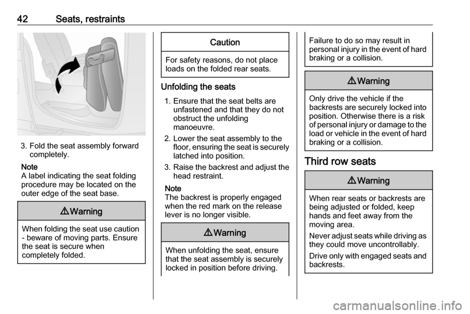
3. Fold the seat assembly forwardcompletely.
Note
A label indicating the seat folding
procedure may be located on the
outer edge of the seat base.
9 Warning
When folding the seat use caution
- beware of moving parts. Ensure
the seat is secure when
completely folded.
Caution
For safety reasons, do not place
loads on the folded rear seats.
Unfolding the seats
1. Ensure that the seat belts are unfastened and that they do not
obstruct the unfolding
manoeuvre.
2. Lower the seat assembly to the floor, ensuring the seat is securely
latched into position.
3. Raise the backrest and adjust the
head restraint.
Note
The backrest is properly engaged
when the red mark on the release
lever is no longer visible.
9 Warning
When unfolding the seat, ensure
that the seat assembly is securely
locked in position before driving.
Failure to do so may result in
personal injury in the event of hard braking or a collision.9 Warning
Only drive the vehicle if the
backrests are securely locked into position. Otherwise there is a risk
of personal injury or damage to the
load or vehicle in the event of hard
braking or a collision.
Third row seats
9 Warning
When rear seats or backrests are
being adjusted or folded, keep
hands and feet away from the
moving area.
Never adjust seats while driving as they could move uncontrollably.
Drive only with engaged seats and
backrests.
Page 46 of 203
44Seats, restraints2. Remove the flexible cord andlower the seat assembly to the
floor, ensuring the rear support is
located on the anchor point and
securely latched into position.
3. Raise the backrest and adjust the
head restraint.
Note
The backrest is properly engaged
when the red mark on the release
lever is no longer visible.9 Warning
When unfolding the seat, ensure
that the seat assembly is securely locked in position before driving.
Failure to do so may result in
personal injury in the event of hard braking or a collision.
9 Warning
Only drive the vehicle if the
backrests are securely locked into position. Otherwise there is a risk
of personal injury or damage to the
load or vehicle in the event of hard braking or a collision.
Removing the seats
Depending on version, the load
compartment area can be increased
by removing the third row seats.
9 Warning
Removable rear seats are heavy!
Do not attempt to remove without assistance.
● Press release buttons and pull the rear seat head restraints
upwards to remove them 3 35.
● Ensure that the seat belts are unfastened and that they do not
obstruct the unfolding
manoeuvre.
● Remove the load compartment cover if necessary 3 64.
1. Fold the seat assembly (refer to "Folding the seats" above).
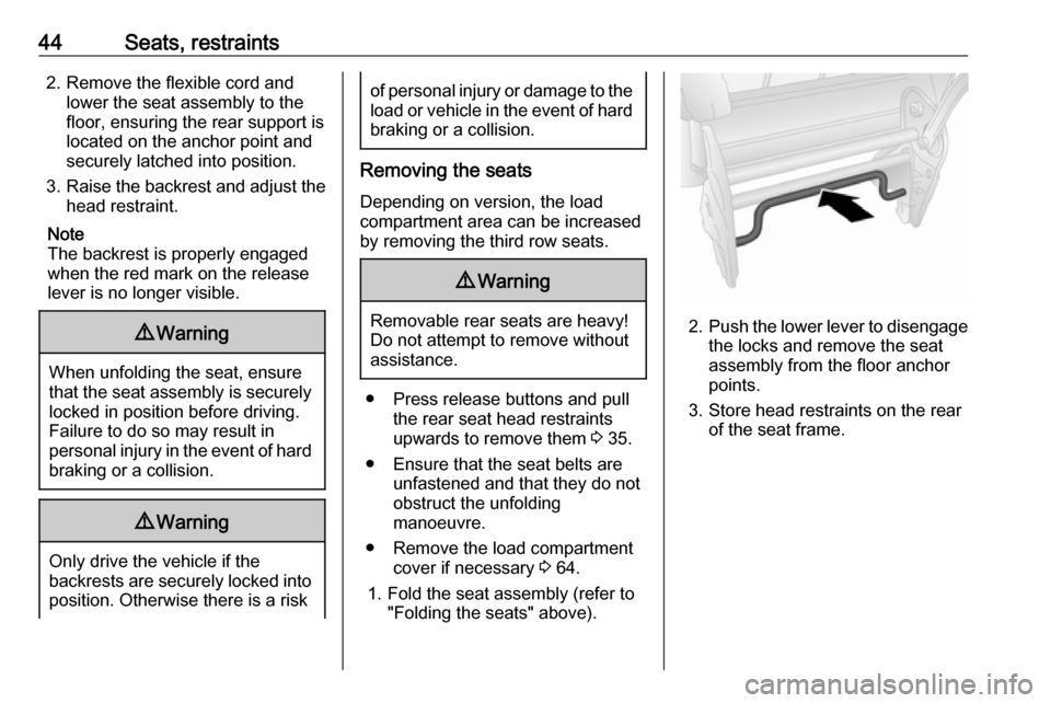
2.Push the lower lever to disengage
the locks and remove the seat
assembly from the floor anchor
points.
3. Store head restraints on the rear of the seat frame.
Page 47 of 203
Seats, restraints45Installing the seats
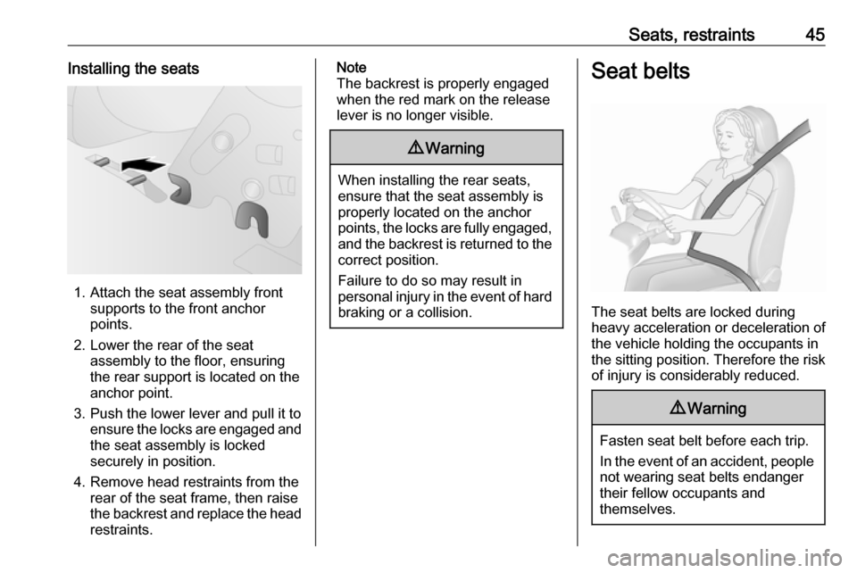
1. Attach the seat assembly frontsupports to the front anchor
points.
2. Lower the rear of the seat assembly to the floor, ensuring
the rear support is located on the
anchor point.
3. Push the lower lever and pull it to ensure the locks are engaged andthe seat assembly is locked
securely in position.
4. Remove head restraints from the rear of the seat frame, then raise
the backrest and replace the head
restraints.
Note
The backrest is properly engaged
when the red mark on the release
lever is no longer visible.9 Warning
When installing the rear seats,
ensure that the seat assembly is
properly located on the anchor
points, the locks are fully engaged, and the backrest is returned to the
correct position.
Failure to do so may result in
personal injury in the event of hard braking or a collision.
Seat belts
The seat belts are locked during
heavy acceleration or deceleration of
the vehicle holding the occupants in
the sitting position. Therefore the risk
of injury is considerably reduced.
9 Warning
Fasten seat belt before each trip.
In the event of an accident, people
not wearing seat belts endanger their fellow occupants and
themselves.
Page 59 of 203

Seats, restraints57Children should travel facing
rearwards in the vehicle as long as
possible. This makes sure that the child's backbone, which is still very
weak, is under less strain in the event
of an accident.
Suitable are restraint systems that
comply with valid UN ECE
regulations. Check local laws and
regulations for mandatory use of child restraint systems.
Ensure that the child restraint system to be installed is compatible with the
vehicle type.
Ensure that the mounting location of
the child restraint system within the
vehicle is correct, see following
tables.
Allow children to enter and exit the
vehicle only on the side facing away
from the traffic.
When the child restraint system is not
in use, secure the seat with a seat belt or remove it from the vehicle.
Note
Do not affix anything on the child
restraint systems and do not cover
them with any other materials.A child restraint system which has
been subjected to stress in an
accident must be replaced.
Child locks 3 25.
Page 64 of 203

62StorageGlovebox
Pull lever to open the glovebox cover.Depending on version, the glovebox
may be lockable using the ignition
key.
The glovebox should be closed whilst
driving.
Cupholders
Cupholders are located in the console between the front seats.
The cupholders can also be used to
hold the portable ashtray unit 3 76.
Front storage
Storage compartments are located in the front door pockets.
Coat hooks are located on the cabin
bulkhead (where fitted).
Overhead console
Store only lightweight items such as
paperwork or maps in the overhead
console.
Page 69 of 203
Storage67
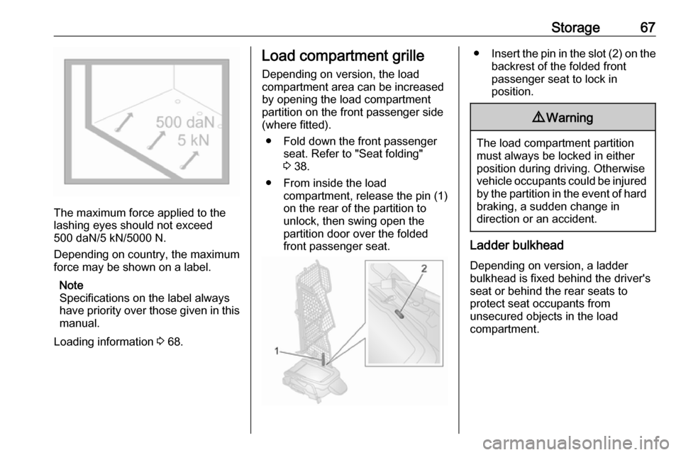
The maximum force applied to the
lashing eyes should not exceed
500 daN/5 kN/5000 N.
Depending on country, the maximum
force may be shown on a label.
Note
Specifications on the label always
have priority over those given in this manual.
Loading information 3 68.
Load compartment grille
Depending on version, the load
compartment area can be increased
by opening the load compartment
partition on the front passenger side
(where fitted).
● Fold down the front passenger seat. Refer to "Seat folding"
3 38.
● From inside the load compartment, release the pin (1)
on the rear of the partition to
unlock, then swing open the
partition door over the folded
front passenger seat.● Insert the pin in the slot (2) on the
backrest of the folded front
passenger seat to lock in
position.9 Warning
The load compartment partition
must always be locked in either
position during driving. Otherwise
vehicle occupants could be injured by the partition in the event of hard
braking, a sudden change in
direction or an accident.
Ladder bulkhead
Depending on version, a ladder
bulkhead is fixed behind the driver's
seat or behind the rear seats to
protect seat occupants from
unsecured objects in the load
compartment.
Page 72 of 203

70Instruments and controlsInstruments and
controlsControls ....................................... 71
Steering wheel adjustment ........71
Steering wheel controls .............71
Horn ........................................... 71
Windscreen wiper/washer .........72
Rear window wiper/washer .......72
Headlamp washer .....................73
Outside temperature ..................73
Clock ......................................... 73
Power outlets ............................. 75
Cigarette lighter ......................... 76
Ashtrays .................................... 76
Warning lights, gauges and indi‐ cators ........................................... 77
Instrument cluster ......................77
Speedometer ............................. 77
Odometer .................................. 77
Trip odometer ............................ 77
Tachometer ............................... 77
Fuel gauge ................................ 78
Fuel selector .............................. 78
Engine coolant temperature gauge ....................................... 79
Service display .......................... 79Transmission display .................80
Control indicators ......................80
Generic warning ........................82
Turn signal ................................. 83
Seat belt reminder .....................83
Airbag and belt tensioners .........83
Airbag deactivation ....................84
Charging system .......................84
Malfunction indicator light ..........84
Brake system ............................. 85
Brake pad wear ......................... 85
Antilock brake system (ABS) .....85
Transmission ............................. 85
Gear shifting .............................. 86
Hill start assist ........................... 86
Ultrasonic parking assist ...........86
Electronic Stability Control ........86
Engine coolant temperature ......87
Preheating ................................. 87
Diesel particle filter ....................87
Tyre pressure monitoring system ...................................... 88
Engine oil pressure ....................88
Change engine oil .....................89
Low engine oil level ...................89
Low fuel ..................................... 89
Drain fuel filter ........................... 90
Immobiliser ................................ 90
Stop-start system ......................90
Exterior light .............................. 90High beam................................. 90
Fog light ..................................... 91
Rear fog light ............................. 91
Cruise control ............................ 91
Door open .................................. 91
Information displays .....................91
Driver Information Centre ..........91
Vehicle messages ........................96
Warning chimes .........................96
Fuel system messages ..............97
Trip computer ............................... 97
Page 73 of 203

Instruments and controls71Controls
Steering wheel adjustment
Unlock lever, adjust steering wheel,
then engage lever and ensure it is
fully locked.
Do not adjust steering wheel unless
vehicle is stationary and steering
wheel lock has been released.
Steering wheel controls
The Infotainment system and a
connected mobile phone can be
operated via the controls on the
steering wheel.
Further information is available in the
Infotainment manual.
Horn
Press j.
The horn will sound regardless of
ignition switch position.
Page 75 of 203
Instruments and controls73Headlamp washer
With low beam on, washer fluid is sprayed onto the headlights when the
windscreen washer is activated
(depending on version).
Note
Washer fluid is not sprayed onto the
headlights if fluid level is too low.
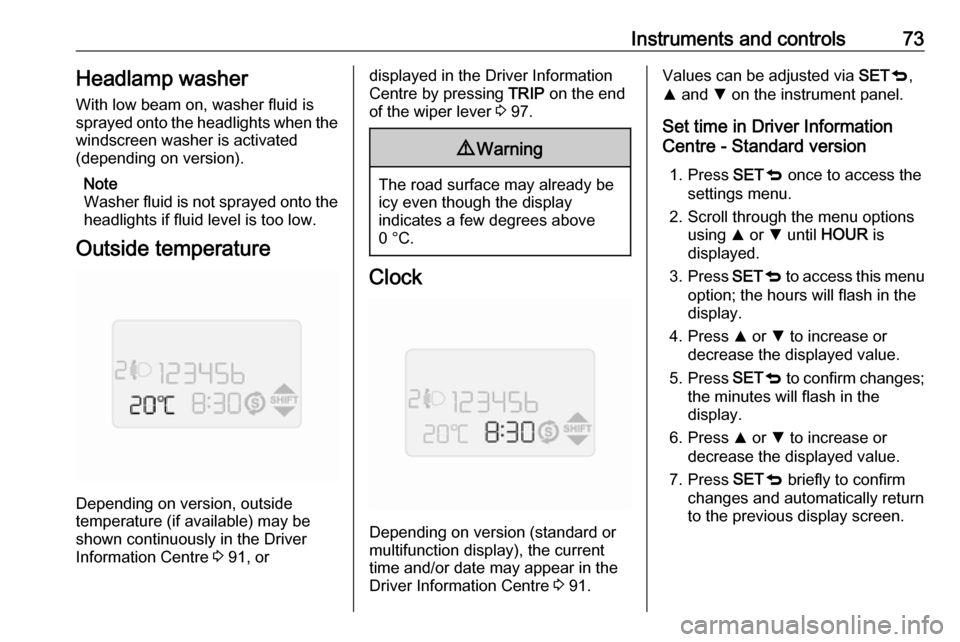
Outside temperature
Depending on version, outside
temperature (if available) may be shown continuously in the DriverInformation Centre 3 91, or
displayed in the Driver Information
Centre by pressing TRIP on the end
of the wiper lever 3 97.9 Warning
The road surface may already be
icy even though the display
indicates a few degrees above
0 °C.
Clock
Depending on version (standard or
multifunction display), the current
time and/or date may appear in the
Driver Information Centre 3 91.
Values can be adjusted via SETq,
R and S on the instrument panel.
Set time in Driver Information
Centre - Standard version
1. Press SETq once to access the
settings menu.
2. Scroll through the menu options using R or S until HOUR is
displayed.
3. Press SETq to access this menu
option; the hours will flash in the display.
4. Press R or S to increase or
decrease the displayed value.
5. Press SETq to confirm changes;
the minutes will flash in the
display.
6. Press R or S to increase or
decrease the displayed value.
7. Press SETq briefly to confirm
changes and automatically return
to the previous display screen.
Page 76 of 203

74Instruments and controlsSet time and date in Driver
Information Centre - Multifunction
version
Setting the time
After accessing this menu option, it is possible to either set the time or
change the clock mode between
12 hour and 24 hour clock.
Press SETq once to access the
settings menu.
Scroll through the menu options using
R or S until Set time is displayed.
Press SETq to access this menu
option; Time is displayed.
To set the time: 1. Press SETq to access the Time
submenu option; the hours will flash in the display.
2. Press R or S to increase or
decrease the displayed value.
3. Press SETq to confirm changes;
the minutes will flash in the
display.4. Press R or S to increase or
decrease the displayed value.
5. Press SETq briefly to confirm
changes.
To change the clock mode between
12 hour and 24 hour clock:
1. After the time has been set, Mode may be displayed
automatically. Alternatively, press
R or S to select this submenu
option.
2. Press SETq to access this
submenu option; the display will
flash.
3. Press R or S to change clock
mode between 12h and 24h.
4. Press SETq briefly to confirm
changes and automatically return
to the previous display screen.
Setting the date 1. Press SETq once to access the
settings menu.
2. Scroll through the menu options using R or S until Set date is
displayed.3. Press SETq to access this menu
option; the year will flash in the
display.
4. Press R or S to increase or
decrease the displayed value.
5. Press SETq to confirm changes;
the month will flash in the display.
6. Press R or S to increase or
decrease the displayed value.
7. Press SETq to confirm changes;
the day will flash in the display.
8. Press R or S to increase or
decrease the displayed value.
9. Press SETq briefly to confirm
changes and automatically return
to the previous display screen.