display OPEL COMBO E 2019.75 Manual user
[x] Cancel search | Manufacturer: OPEL, Model Year: 2019.75, Model line: COMBO E, Model: OPEL COMBO E 2019.75Pages: 285, PDF Size: 10.68 MB
Page 196 of 285

194Driving and operatingObjects with a very small reflection
cross-section, e.g. objects of
narrow size or soft materials, may
not be detected by the system.
Parking assist systems do not
detect objects outside the
detection range.
Note
It is possible that the sensor detects a non-existing object caused by
echo disturbance from external
acoustic noise or mechanical
misalignments (sporadic false
warnings may occur).
Make sure that the front number
plate is properly mounted (not bent
and no gaps to the bumper on the left
or right side) and the sensors are
firmly in place.
Advanced parking assist system
may not respond to changes in the
available parking space after
initiating a parking manoeuvre. The
system may recognize an entry, a
gateway, a courtyard or even a crossing as a parking slot. After
selecting reverse gear the system
will start a parking manoeuvre. Take
care regarding the availability of the
suggested parking slot.
Surface irregularities, e.g. on
construction zones, are not detected
by the system. The driver accepts
responsibility.
Side blind spot alert
The side blind spot alert system
detects and reports objects on either
side of the vehicle, within a specified
blind spot zone. The system displays
a visual alert in each exterior mirror,
when detecting objects that may not
be visible in the interior and exterior
mirrors.
Side blind spot alert uses some of the
advanced parking assist sensors
which are located in the front and rear bumper on both sides of the vehicle.9 Warning
Side blind spot alert does not
replace driver vision.
The system does not detect:
● vehicles outside the side blind zones which may be rapidly
approaching
● pedestrians, cyclists or animals
Before changing a lane, always
check all mirrors, look over the
shoulder and use the turn signal.
Activation
Colour Info Display: press Í. Select
Driving functions on the Info Display
and then Blind spot sensors . Activate
the function.
B illuminates continously green in the
instrument cluster to confirm the
function.
Page 198 of 285

196Driving and operatingThe state of the system is stored
when switching off the ignition.
The system is automatically
deactivated when towing an
electrically connected trailer.
Due to adverse weather conditions
such as heavy rain, false detections
may occur.
Fault
In the event of a fault, B flashes for a
few moments in the instrument panel,
accompanied by C and a display
message. Have the cause of the fault remedied by a workshop.
Passenger side camera
The passenger side camera monitors the side of the vehicle.
The camera is mounted at the bottom of the exterior mirror on the
passenger side.
The passenger side view is displayed
in the rear view display 3 116.
The area displayed by the camera is
limited. The distance of the image that
appears on the display differs from
the actual distance.
Switching on
The camera is switched on when the vehicle is running in forward gear and
the passenger side view is selectedfrom the rear view display.
Guidelines
The line represents a distance of
about 4 m beyond the edge of
vehicle's rear bumper.
Switching off The camera is deactivated when
another view type is selected.
Panoramic view system
This system allows views of the
vehicle's surroundings to be
displayed as a nearly 180° picture in
the Info display, like a bird's eye view.
Page 199 of 285

Driving and operating197The system uses:● rear camera, installed in the tailgate
● ultrasonic parking sensors in the rear bumper
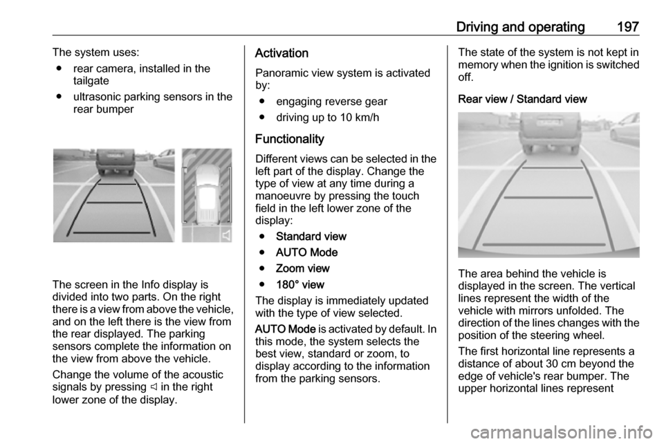
The screen in the Info display is
divided into two parts. On the right
there is a view from above the vehicle,
and on the left there is the view from
the rear displayed. The parking
sensors complete the information on
the view from above the vehicle.
Change the volume of the acoustic
signals by pressing C in the right
lower zone of the display.
Activation
Panoramic view system is activated
by:
● engaging reverse gear
● driving up to 10 km/h
Functionality
Different views can be selected in the left part of the display. Change the
type of view at any time during a
manoeuvre by pressing the touch
field in the left lower zone of the
display:
● Standard view
● AUTO Mode
● Zoom view
● 180° view
The display is immediately updated
with the type of view selected.
AUTO Mode is activated by default. In
this mode, the system selects the
best view, standard or zoom, to
display according to the information
from the parking sensors.The state of the system is not kept in memory when the ignition is switched
off.
Rear view / Standard view
The area behind the vehicle is
displayed in the screen. The vertical
lines represent the width of the
vehicle with mirrors unfolded. The
direction of the lines changes with the position of the steering wheel.
The first horizontal line represents a
distance of about 30 cm beyond the
edge of vehicle's rear bumper. The
upper horizontal lines represent
Page 200 of 285

198Driving and operatingdistances of about 1 and 2 m beyond
the edge of your vehicle's rear
bumper.
This view is available in AUTO Mode
or in the view selection menu.
Rear zoom view / Zoom view
The camera records the vehicle's
surroundings during the manoeuvre in order to reconstruct a view fromabove the rear of the vehicle in its
near surroundings, allowing the
vehicle to be manoeuvred around
obstacles nearby. This view is
available with AUTO Mode or in the
view selection menu.
Rear side view / 180° view
The 180° view facilitates reversing
out of a parking bay, making it
possible to see the approach of
vehicles, pedestrians and cyclists.
This view is not recommended for
carrying out a complete manoeuvre.
It is made up of three areas: left 1,
centre 2 and right 3. This view is
available from the view selection menu only.
Deactivation
Panoramic view system is
deactivated when:
● driving faster than 10 km/h
● seven seconds after disengaging
reverse gear
● by pressing the icon Ù in the left
upper corner of the touch screen
and then &
● opening the tailgate
● attaching a trailer or a bike carrier
General information9 Warning
The panoramic view system does
not replace driver vision. It will not display children, pedestrians,
cyclists, crossing traffic, animals,
or any other objects outside of the camera view area, e. g. below the
bumper, or underneath the
vehicle.
Do not drive or park the vehicle
using only the panoramic view
system.
Page 201 of 285

Driving and operating199Always check the surrounding of
the vehicle before driving.
Displayed images may be further
or closer than they appear. The
area displayed is limited and
objects that are close to either
edge of the bumper or under the
bumper are not displayed on the
screen.
System limitations
Caution
For optimal operation of the
system, it is important to keep the
lense of the camera in the tailgate between the number plate lightsalways clean. Rinse the lense with water and wipe with a soft cloth.
Do not clean the lense with a
steam-jet or high-pressure jet
cleaner.
The panoramic view system may not
operate properly when:
● The surrounding is dark.
● The sun or the beam of headlights is shining directly into
the camera lenses.
● During nighttime driving.
● Weather limits visibility, such as fog, rain, or snow.
● The camera lenses are blocked by snow, ice, slush, mud, dirt.
● The vehicle is towing a trailer.
● The vehicle had an accident.
● There are extreme temperature changes.
Rear view camera Depending on version, camera is
mounted above the license plate in
the tailgate / left rear door or at the top
of the left rear door.9 Warning
The rear view camera does not
replace driver vision. Note that
objects that are outside the
camera's field of view and the
parking assist sensors, e.g. below
the bumper or underneath the
vehicle, are not displayed.
Do not reverse or park the vehicle
using only the rear view camera.
Always check the surrounding of
the vehicle before driving.
Camera above the license plate
on the tailgate / left rear door
Page 202 of 285

200Driving and operatingThe view of the camera is displayed
in the Info Display 3 113.
The area displayed by the camera is
limited. The distance of the image that
appears on the display differs from
the actual distance.
Switching on
Rear view camera is automatically
activated when reverse gear is
engaged.
Guidelines
Dynamic guidelines are horizontal
lines at one metre intervals projected
onto the picture to define the distance
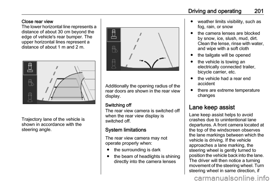
to displayed objects.Trajectory lane of the vehicle is
shown in accordance with the
steering angle.
Switching off
The camera is switched off when a
forward gear is engaged.
Camera at top of the left rear door
The view of the camera is displayed
in the rear view display 3 116.
Switching on
The rear view camera is automatically switched on.
The standard rear view is activated
when a forward gear is engaged.
The close rear view is activated when selected via p in the rear view
display or when the reverse gear is engaged.
When operating with a trailer, the
close rear view is no longer operable.
GuidelinesStandard rear view
The horizontal line represents a
distance of about 4 m beyond the
edge of vehicle's rear bumper.
Page 203 of 285

Driving and operating201Close rear view
The lower horizontal line represents a
distance of about 30 cm beyond the
edge of vehicle's rear bumper. The
upper horizontal lines represent a
distance of about 1 m and 2 m.
Trajectory lane of the vehicle is
shown in accordance with the
steering angle.
Additionally the opening radius of the
rear doors are shown in the rear view display.
Switching off
The rear view camera is switched off
when the rear view display is
switched off.
System limitationsThe rear view camera may not
operate properly when:
● the surrounding is dark
● the beam of headlights is shining
directly into the camera lenses
● weather limits visibility, such as fog, rain, or snow
● the camera lenses are blocked by snow, ice, slush, mud, dirt.
Clean the lense, rinse with water, and wipe with a soft cloth
● the tailgate will be opened
● the vehicle is towing an electrically connected trailer,
bicycle carrier, etc.
● the vehicle had a rear end accident
● there are extreme temperature changes
Lane keep assist
Lane keep assist helps to avoid
crashes due to unintentional lane
departures. A front camera located at the top of the windscreen observes
the lane markings between which the
vehicle is driving. If the vehicle
approaches a lane marking, the
steering wheel is gently turned to
position the vehicle back into the lane. The driver will then notice a turning
movement of the steering wheel. Turn
steering wheel in same direction, if
Page 205 of 285

Driving and operating203If the driver wishes to maintain thetrajectory of the vehicle, he can
prevent the correction by keeping a
firm grip on the steering wheel, e.g.
during an avoiding manoeuvre. The
correction is interrupted if the turn
lights are operated.
There is no correction triggered when
the turn lights are operated and
during a few seconds after turn lights
have been switched off.
If the system detects that the driver is
not holding the steering wheel firmly enough during an automatic
correction of trajectory, it interrupts the correction. A warning message in the Driver Information Centre
accompanied by a warning chime
alerts the driver when immediate
driver´s action is required.
If the side blind spot alert is activated
and the driver is about to change the
lane, the system corrects the
trajectory of the vehicle despite the
activation of the turn lights if another
vehicle is detected in the side blind
spot zone.Deactivation
To deactivate the system, press andhold Ó. Deactivation of the system is
confirmed by the illuminated LED in
the button. In the Driver Information
Centre solid grey lines are displayed.
Recommended deactivation It is recommended to deactivate the
system in the following situations:
● Road surface in poor condition
● Unfavourable climatic conditions
● Slippery surfaces, e.g., ice
The system is not designed for driving in the following situations:
● Driving on a speed circuit
● Driving with a trailer
● Driving on a rolling stand
● Driving on unstable surfacesFault
In the event of a fault, a and C
appear in the instrument panel,
accompanied by a display message
and a warning chime. Contact a
dealer or a qualified workshop to have the system checked.
System limitations The system performance may be
affected by:
● windscreen not clean or affected by foreign objects, e.g. stickers
● close vehicles ahead
● banked roads
● narrow, winding or hilly roads
● road edges
● sudden lighting changes
● adverse environmental conditions, e.g. heavy rain or
snow
● vehicle modifications, e.g. tyres
Page 233 of 285

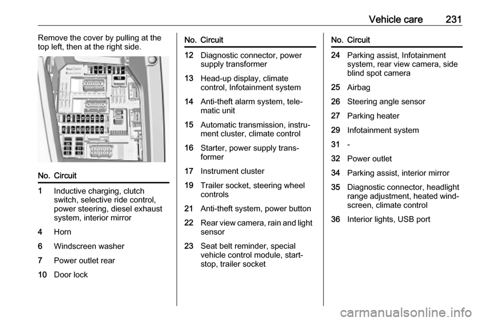
Vehicle care231Remove the cover by pulling at the
top left, then at the right side.No.Circuit1Inductive charging, clutch
switch, selective ride control,
power steering, diesel exhaust
system, interior mirror4Horn6Windscreen washer7Power outlet rear10Door lockNo.Circuit12Diagnostic connector, power
supply transformer13Head-up display, climate
control, Infotainment system14Anti-theft alarm system, tele‐
matic unit15Automatic transmission, instru‐
ment cluster, climate control16Starter, power supply trans‐
former17Instrument cluster19Trailer socket, steering wheel
controls21Anti-theft system, power button22Rear view camera, rain and light sensor23Seat belt reminder, special
vehicle control module, start-
stop, trailer socketNo.Circuit24Parking assist, Infotainment
system, rear view camera, side
blind spot camera25Airbag26Steering angle sensor27Parking heater29Infotainment system31-32Power outlet34Parking assist, interior mirror35Diagnostic connector, headlight
range adjustment, heated wind‐ screen, climate control36Interior lights, USB port
Page 236 of 285

234Vehicle careThe tyre pressure information labelon the left door frame indicates the
original equipment tyres and the
correspondent tyre pressures.
The tyre pressure data refers to cold
tyres. It applies to summer and winter tyres.
Always inflate the spare tyre to the
pressure specified for full load.
Incorrect tyre pressures will impair
safety, vehicle handling, comfort and
fuel economy and will increase tyre
wear.
Tyre pressures differ depending on
various options. For the correct tyre
pressure value, follow the procedure
below:
1. Identify the engine identifier code.
Engine data 3 263.
2. Identify the respective tyre.
The tyre pressure tables show all possible tyre combinations 3 266.
For the tyres approved for your
vehicle, refer to the EEC Certificate of
Conformity provided with your vehicle
or other national registration
documents.The driver is responsible for correct
adjustment of tyre pressure.9 Warning
If the pressure is too low, this can
result in considerable tyre warm-
up and internal damage, leading to tread separation and even to tyre
blow-out at high speeds.
9 Warning
For specific tyres the
recommended tyre pressure as
shown in the tyre pressure table may exceed the maximum tyre
pressure as indicated on the tyre.
Never exceed the maximum tyre
pressure as indicated on the tyre.
Temperature dependency
The tyre pressure depends on the
temperature of the tyre. During
driving, tyre temperature and
pressure increase. Tyre pressure
values provided on the tyre
information label and tyre pressure
chart are valid for cold tyres, which means at 20 °C.
The pressure increases by nearly
10 kPa for a 10 °C temperature
increase. This must be considered
when warm tyres are checked.
Tyre deflation detectionsystem
The tyre deflation detection system
continually checks the rotation speed
of all four wheels and warns on low
tyre pressure condition once vehicle
is driving. This is achieved by
comparing tyre rolling circumference
with reference values and further
signals.
If a tyre loses pressure the control
indicator w illuminates, a warning
chime is given and a warning
message is displayed in the Driver
Information Centre.
In this case reduce speed, avoid
sharp cornering and strong braking.
Stop at next safe opportunity and
check tyre pressure.
Control indicator w 3 108.