warning OPEL COMBO E 2019 Manual user
[x] Cancel search | Manufacturer: OPEL, Model Year: 2019, Model line: COMBO E, Model: OPEL COMBO E 2019Pages: 279, PDF Size: 10.43 MB
Page 209 of 279

Driving and operating2071. Move the lever to the rearposition.
2. Clean the contact points with asoft clean cloth.
3. Insert the coupling ball bar in theopening and push firmly up to the
stop.
Secure the coupling ball bar
correctly by moving the lever to
the locked position, shown in the
picture.
4. Attach the trailer.
5. Connect the trailer plug to the socket.
6. Attach the breakaway stoppingcable to the eye on the carrier.
9 Warning
Towing a trailer is permitted only
when a coupling ball bar is fitted correctly. If the coupling ball bardoes not engage correctly, seekthe assistance of a workshop.
Dismounting coupling ball bar
1. Disconnect the trailer plug.
2. Unfasten the breakaway stopping
cable.
3. Remove the trailer.
Page 214 of 279

212Vehicle careEnd-of-life vehicle recoveryInformation on end-of-life vehicle
recovery centres and the recycling of
end-of-life vehicles is available on our website, where legally required. Only
entrust this work to an authorised
recycling centre.Vehicle checks
Performing work9 Warning
Only perform engine compartment
checks when the ignition is off.
The cooling fan may start
operating even if the ignition is off.
9 Danger
The ignition system uses
extremely high voltage. Do not
touch.
Bonnet
Opening
Open the driver's door.
Pull the release lever and return it to
its original position.
Page 216 of 279

214Vehicle careDifferent dipsticks are used
depending on engine variant.
When the engine oil level has
dropped to the MIN mark, top up the
engine oil.
We recommend the use of the same
grade of engine oil that was used at
last change.
The engine oil level must not exceed the MAX mark on the dipstick.
Caution
Overfilled engine oil must be
drained or suctioned out. If the oil exceeds the maximum level, do
not start the vehicle and contact a
workshop.
Capacities 3 262.
Fit the cap on straight and tighten it.
Engine coolant The coolant provides freeze
protection down to approx. -37 °C.
Caution
Only use approved antifreeze.
Coolant and antifreeze 3 252.
Coolant level
Caution
Too low a coolant level can cause engine damage.
If the cooling system is cold, the
coolant level should be above the
MIN mark. Top up if the level is low.
9Warning
Allow the engine to cool before
opening the cap. Carefully open
the cap, relieving the pressure
slowly.
To top up, use a 1:1 mixture of
released coolant concentrate mixed
with clean tap water. If no coolant
concentrate is available, use clean
tap water. Install the cap tightly. Have
Page 217 of 279

Vehicle care215the coolant concentration checked
and have the cause of the coolant
loss remedied by a workshop.
Washer fluid
Fill with clean water mixed with a
suitable quantity of approved
windscreen washer fluid which
contains antifreeze.
The washer fluid level has to be
underneath the MAX mark.
Caution
Only washer fluid with a sufficient
antifreeze concentration provides
protection at low temperatures or
a sudden drop in temperature.
Washer fluid 3 252.
Brakes In the event of minimum thickness of
the brake lining, a squealing noise
sounds during braking.
Continued driving is possible but
have the brake lining replaced as
soon as possible.
Once new brake linings are installed,
do not brake unnecessarily hard for
the first few journeys.
Brake fluid
9 Warning
Brake fluid is poisonous and
corrosive. Avoid contact with eyes,
skin, fabrics and painted surfaces.
The brake fluid level must be betweenthe DANGER and MAX marks.
If fluid level is below DANGER, seek
the assistance of a workshop.
Brake and clutch fluid 3 252.
Vehicle battery
The vehicle battery is maintenance-
free provided that the driving profile
allows sufficient charging of the
battery. Short-distance-driving and
frequent engine starts can discharge
the battery. Avoid the use of
unnecessary electrical consumers.
Page 218 of 279

216Vehicle care
Batteries do not belong in household
waste. They must be disposed of at
an appropriate recycling collection
point.
Laying up the vehicle for more than
four weeks can lead to battery
discharge. Disconnect the clamp from the negative terminal of the vehicle
battery.
Ensure the ignition is switched off
before connecting or disconnecting
the vehicle battery.
Battery discharge protection 3 130.
Replacing the vehicle battery Note
Any deviation from the instructions
given in this section may lead to
temporary deactivation or
disturbance of the stop-start system.
When the vehicle battery is being
replaced, please ensure that there
are no open ventilation holes in the
vicinity of the positive terminal. If a
ventilation hole is open in this area, it
must be closed off with a dummy cap, and the ventilation in the vicinity of the negative terminal must be opened.
Ensure that the battery is always
replaced by the same type of battery.
The vehicle battery has to be
replaced by a workshop.
Stop-start system 3 148.
Charging the vehicle battery9 Warning
On vehicles with stop-start
system, ensure that the charging potential does not exceed 14.6 V
when using a battery charger.
Otherwise the vehicle battery may be damaged.
Jump starting 3 242.
Warning label
Meaning of symbols:
● No sparks, naked flames or smoking.
● Always shield eyes. Explosive gases can cause blindness or
injury.
● Keep the vehicle battery out of reach of children.
● The vehicle battery contains sulphuric acid which could cause
blindness or serious burn
injuries.
Page 225 of 279

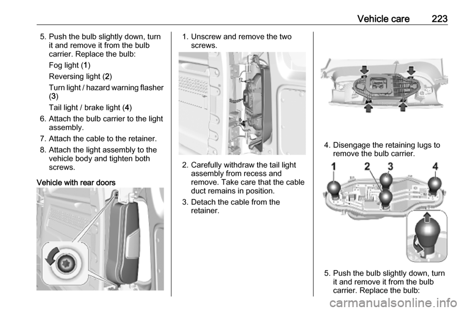
Vehicle care2235. Push the bulb slightly down, turnit and remove it from the bulb
carrier. Replace the bulb:
Fog light ( 1)
Reversing light ( 2)
Turn light / hazard warning flasher ( 3 )
Tail light / brake light ( 4)
6. Attach the bulb carrier to the light assembly.
7. Attach the cable to the retainer.
8. Attach the light assembly to the vehicle body and tighten both
screws.
Vehicle with rear doors1. Unscrew and remove the two screws.
2. Carefully withdraw the tail lightassembly from recess and
remove. Take care that the cable
duct remains in position.
3. Detach the cable from the retainer.
4. Disengage the retaining lugs toremove the bulb carrier.
5. Push the bulb slightly down, turnit and remove it from the bulb
carrier. Replace the bulb:
Page 226 of 279

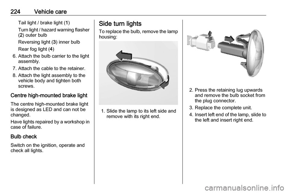
224Vehicle careTail light / brake light (1)
Turn light / hazard warning flasher ( 2 ) outer bulb
Reversing light ( 3) inner bulb
Rear fog light ( 4)
6. Attach the bulb carrier to the light assembly.
7. Attach the cable to the retainer. 8. Attach the light assembly to the vehicle body and tighten both
screws.
Centre high-mounted brake light The centre high-mounted brake light
is designed as LED and can not be
changed.
Have lights repaired by a workshop in case of failure.
Bulb check
Switch on the ignition, operate and
check all lights.Side turn lights
To replace the bulb, remove the lamp
housing:
1. Slide the lamp to its left side and remove with its right end.
2. Press the retaining lug upwards and remove the bulb socket from
the plug connector.
3. Replace the complete unit.
4. Insert left end of the lamp, slide to
the left and insert right end.
Page 233 of 279

Vehicle care231The driver is responsible for correct
adjustment of tyre pressure.9 Warning
If the pressure is too low, this can
result in considerable tyre warm-
up and internal damage, leading to tread separation and even to tyre
blow-out at high speeds.
9 Warning
For specific tyres the
recommended tyre pressure as
shown in the tyre pressure table may exceed the maximum tyre
pressure as indicated on the tyre.
Never exceed the maximum tyre
pressure as indicated on the tyre.
Temperature dependency
The tyre pressure depends on the
temperature of the tyre. During
driving, tyre temperature and
pressure increase. Tyre pressure
values provided on the tyre
information label and tyre pressure
chart are valid for cold tyres, which means at 20 °C.
The pressure increases by nearly
10 kPa for a 10 °C temperature
increase. This must be considered
when warm tyres are checked.
Tyre deflation detectionsystem
The tyre deflation detection system
continually checks the rotation speed
of all four wheels and warns on low
tyre pressure condition once vehicle
is driving. This is achieved by
comparing tyre rolling circumference
with reference values and further
signals.
If a tyre loses pressure the control
indicator w illuminates, a warning
chime is given and a warning
message is displayed in the Driver
Information Centre.
In this case reduce speed, avoid
sharp cornering and strong braking.
Stop at next safe opportunity and
check tyre pressure.
Control indicator w 3 109.After adjusting tyre pressure initialise
system to extinguish the control
indicator and restart system.Caution
Deflation detection system warns
just about low tyre pressure
condition and does not replace
regular tyre maintenance by the
driver.
In case of a system malfunction a
message is displayed in the Driver
Information Centre. Set correct tyre
pressure and reinitialise system. If the
failure continues to be displayed,
contact a workshop. The system is
inoperable when ABS or ESC has a
malfunction or a temporary spare
wheel is used. Once the road tyre has
been refitted, check the tyre pressure with cold tyres and initialise the
system.
System initialisation
After tyre pressure correction or
wheel change, the system must be
initialised to learn new circumference reference values:
Page 235 of 279

Vehicle care233Tyres age, even if they are not used.
We recommend tyre replacement
every six years.
Changing tyre and wheel
size
If tyres of a different size than thosefitted at the factory are used, it may be
necessary to reprogramme the tyre
deflation detection system and make
other vehicle modifications.
Tyre deflation detection system
3 231.
Have the label with tyre pressures
replaced.9 Warning
The use of unsuitable tyres or
wheels may lead to accidents and will invalidate the vehicle
operating permit.
Wheel covers
Wheel covers and tyres that are
factory approved for the respective
vehicle and comply with all of the
relevant wheel and tyre combination
requirements must be used.
If the wheel covers and tyres used are
not factory approved, the tyres must
not have a rim protection ridge.
Wheel covers must not impair brake
cooling.9 Warning
Use of unsuitable tyres or wheel
covers could lead to sudden
pressure loss and thereby
accidents.
Vehicles with steel wheels: When
using locking wheel nuts, do not
attach wheel covers.
Tyre chains
Tyre chains are only permitted on the
front wheels.
Always use fine mesh chains that add no more than 9 mm to the tyre tread
and the inboard sides (including chain
lock).
9 Warning
Damage may lead to tyre blowout.
Tyre chains are permitted on all tyres
sizes allowed for the vehicle.
Page 236 of 279

234Vehicle careTemporary spare wheel
The use of tyre chains is not permitted
on the temporary spare wheel.
Tyre repair kit
Minor damage to the tyre tread can be repaired with the tyre repair kit.
Do not remove foreign bodies from
the tyres.
Tyre damage exceeding 4 mm or that
is at tyre's sidewall cannot be repaired with the tyre repair kit.9 Warning
Do not drive faster than 80 km/h.
Do not use for a lengthy period.
Steering and handling may be
affected.
In the case of a flat tyre:
Apply the parking brake and engage
first gear, reverse gear or P.
Open the cover of the footwell storage
3 74.
The tyre repair kit is located in the
stowage compartment underneath
the right front seat.
1. Remove the sealant bottle and the
compressor.
2. Pull speed limit label from sealant
bottle and place it in driver's
visible area.3. Remove the electrical connection cable and air hose from the
stowage compartments on the
underside of the compressor.