tow OPEL CORSA 2009 Owner's Guide
[x] Cancel search | Manufacturer: OPEL, Model Year: 2009, Model line: CORSA, Model: OPEL CORSA 2009Pages: 284, PDF Size: 4.96 MB
Page 193 of 284
187
Driving and operation
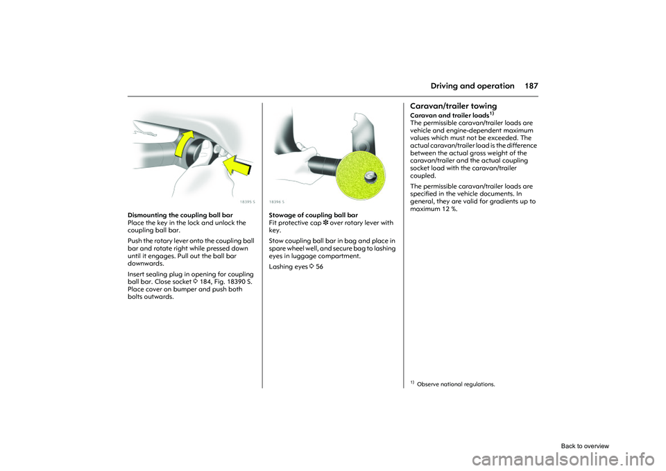
Picture no: 18395s.tif
Dismounting the coupling ball bar
Place the key in the lock and unlock the
coupling ball bar.
Push the rotary lever onto the coupling ball
bar and rotate right while pressed down
until it engages. Pull out the ball bar
downwards.
Insert sealing plug in opening for coupling
ball bar. Close socket 3184, Fig. 18390 S.
Place cover on bumper and push both
bolts outwards.
Picture no: 18396s.tif
Stowage of coupling ball bar
Fit protective cap 3 over rotary lever with
key.
Stow coupling ball bar in bag and place in
spare wheel well, and se cure bag to lashing
eyes in luggage compartment.
Lashing eyes 356
Caravan/trailer towingCaravan and trailer loads
1)
The permissible caravan/trailer loads are
vehicle and engine-dependent maximum
values which must not be exceeded. The
actual caravan/trailer load is the difference
between the actual gross weight of the
caravan/trailer and the actual coupling
socket load with the caravan/trailer
coupled.
The permissible caravan/trailer loads are
specified in the vehicle documents. In
general, they are valid for gradients up to
maximum 12 %. 1)Observe national regulations.
Back to overview
Page 194 of 284
188 Driving and operationThe permitted caravan/trailer load applies
up to the specified incline and up to an
altitude of 1000 metres above sea level.
Since engine power decreases as altitude
increases because of the air becoming
thinner, therefore reducing climbing ability,
the permitted towing weight also
decreases by 10 % for every 1000 metres of
additional altitude. The towing weight
does not have to be reduced when driving
on roads with slight inclines (less than 8 %,
e. g. motorways).
The permissible gross train weight must not
be exceeded. This weight is specified on
the identification plate 3250. Coupling socket load
The coupling socket load is the load
exerted by the trailer/caravan on the
coupling ball. It can be varied by changing
the weight distributi
on when loading the
trailer/caravan.
The maximum permitted coupling socket
load (vehicles with engine Z 12 XEP: 45 kg,
other versions: 55 kg) of the towing vehicle
is noted on the identification plate of the
trailer towing device and specified in the
vehicle documents. This must always be
complied with, partic ularly when towing
heavy trailers. The coupling socket load
must never be less than 25 kg.
When measuring the coupling socket load,
make sure that the drawbar of the loaded
trailer/caravan is at the same height as it
will be when the trailer/caravan is coupled
with the towing vehicl e loaded. Particularly
important for trailers/caravans with
tandem axle. Rear axle load during towing
With the trailer attached and the towing
vehicle fully loaded, including all the
passengers, the permitted rear axle load
(specified on identifica
tion plate and vehicle
documents) for passenger vehicles may be
exceeded by 45 kg and the permitted total
load may be exceeded by 50 kg.
For vans the permitted rear axle load may
be exceeded by 25 kg. The permitted total
load may be exceeded by the following
amounts with the engines specified below:
Trailer operation is not permitted for vans
with tyre size 215/45 R 17.
If the permitted rear axle load is exceeded
a maximum speed of 100 km/h applies. If
lower national maximum speeds are
specified for trailer operation, they must be
complied with. Z 10 XEP 30 kg
Z 12 XEP 15 kg
Z 13 DTH 40 kg
Z 13 DTJ 35 kg
Back to overview
Page 195 of 284
189
Driving and operation
Driving characteristics, towing tips
Before attaching the trailer/caravan,
lubricate the ball of the trailer/caravan
towing device. However, do not lubricate
the ball if a stabiliser, which acts on the
coupling ball, is being used to damp
hunting.
Check caravan/traile r lighting before
starting to drive. The fog tail lamps on the
vehicle are deactivated when towing a
caravan or trailer.
Trailers with LED turn signals must have a
provision enables lamp monitoring for
commercial bulbs.
Ultrasonic parking sensors 3 are
deactivated in towing mode.
Handling is greatly influenced by the
loading of the trailer/caravan. Loads
should therefore be secured so that they
cannot slip and be placed in the centre of
the trailer/caravan if possible, i.e. above
the axle.
For trailers with low directional control and
for caravans with a permissible gross
vehicle weight of more than 1000 kg, a
speed of 80 km/h must not be exceeded;
use of a roll damper in accordance with the
friction principle is urgently recommended. If the trailer/caravan starts to sway, drive
more slowly, do not attempt to correct the
steering and brake sharply if necessary.
If it is necessary to apply the brakes fully,
depress the brake pedal as hard as
possible.
Remember that the braking distance for
vehicles towing caravans/trailers with and
without brake is always greater than that
for vehicles not towing a caravan/trailer.
When driving downhill, drive in the same
gear as if driving uphill and drive at a
similar speed.
Adjust tyre pressure to the value specified
for full load
3264. Starting on inclines
For vehicles with manual transmission, the
most favourable engine speed when
starting off on an incline is between
2500 and 3000 rpm for petrol engines and
between 2000 and 2200 rpm for diesel
engines. Hold engine speed constant,
engage clutch gradually (let slip), release
hand brake and open throttle. If possible,
the engine speed should not drop during
this procedure.
In vehicles with automatic transmission
3
and manual transmission automated 3 it is
sufficient to give full throttle in D or
(in automatic mode) 3.
Before starting off under extreme
operating conditions, switch off
unnecessary consumers.
Back to overview
Page 196 of 284

190 Self-help, vehicle careSelf-help,
vehicle care
Diesel fuel system, bleeding If the tank is allowed to run dry, the diesel
fuel system must be bled. Turn over the
ignition three times for 15 seconds at a
time. Then start the engine for a maximum
of 40 seconds
1). Repeat this process after
no less than 5 seconds. If the engine fails to
start, seek the assistance of a workshop.
Picture no: 18190s.tif
Bonnet Pull the release lever located on the left
side below the instru ment panel and push
it back to its original position.
Diesel fuel system, bleeding ............... 190
Bonnet .................................................. 190
Starting the engine with jump leads
3. 191
Towing .................................................. 193
Warning triangle ¨ 3......................... 196
First-aid kit (cushion) + 3................... 196
Spare wheel 3...................................... 196
Jack £ 3 and vehicle tools 3........... 198
Changing wheels ................................. 200
Tyre repair kit 3................................... 204
Electrical system .................................. 208
Fuses and the most important circuits they protect ....................................... 209
Bulb replacement ................................ 212
Halogen headlamp system ................ 212
Adaptive Forward Lighting system 3. 216
Front indicator lamps .......................... 220
Fog lamps 3......................................... 220
Side turn signal lamp .......................... 220
Tail lamps ............................................. 221
Number plate lamp ............................. 225
Courtesy lamps .................................... 226
Vehicle care.......................................... 228
1)For technical reasons only 30 seconds are
possible on engines A 17 DTR/Z 17 DTR
Back to overview
Page 197 of 284
191
Self-help, vehicle care
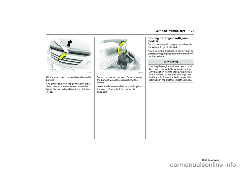
Picture no: 18191s.tif
Lift the safety catch upwards and open the
bonnet.
Any dirt or snow on the bonnet can slide
down toward the windscreen when the
bonnet is opened and block the air intake
3135.
Picture no: 18413s.tif
Secure the bonnet support. Before closing
the bonnet, press the support into the
holder.
Lower the bonnet and allow it to drop into
the catch. Check that the bonnet is
engaged.
Starting the engine with jump
leads
3
Do not use a rapid charger or push or two
the vehicle to get it started.
A vehicle with a discha rged battery can be
started using jump leads and the battery of
another vehicle.
9
Warning
Starting the engine with jump leads must
be carried out with the utmost caution.
Any deviation from the following instruc-
tion may lead to injury or damage due
to the explosion of the batteries and to
damage of the electrics in both vehicles.
Back to overview
Page 199 of 284
193
Self-help, vehicle care
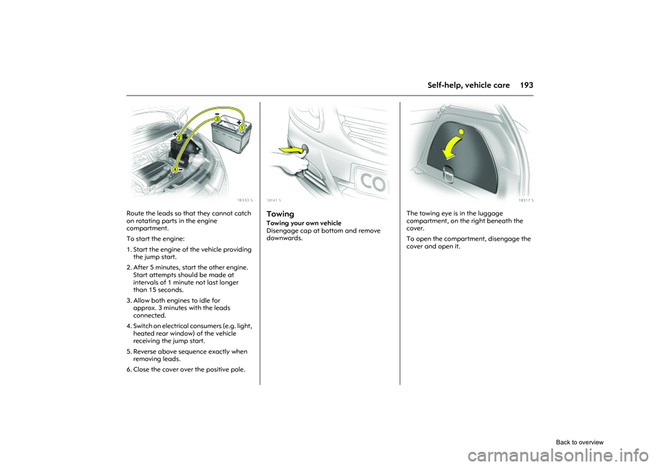
Picture no: 18333s.tif
Route the leads so that they cannot catch
on rotating parts in the engine
compartment.
To start the engine:
1. Start the engine of the vehicle providing the jump start.
2. After 5 minutes, start the other engine. Start attempts shou ld be made at
intervals of 1 minute not last longer
than 15 seconds.
3. Allow both engines to idle for approx. 3 minutes with the leads
connected.
4. Switch on electrical consumers (e.g. light, heated rear window) of the vehicle
receiving the jump start.
5. Reverse above sequence exactly when removing leads.
6. Close the cover over the positive pole.
Picture no: 18141s.tif
Towing Towing your own vehicle
Disengage cap at bottom and remove
downwards.
Picture no: 18317s.tif
The towing eye is in the luggage
compartment, on the right beneath the
cover.
To open the compartment, disengage the
cover and open it.
Back to overview
Page 200 of 284
194 Self-help, vehicle care
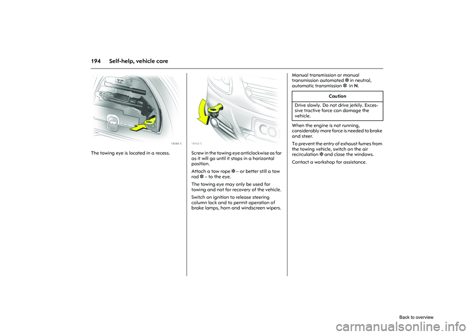
Picture no: 18586s.tif
The towing eye is located in a recess.
Picture no: 18142s.tif
Screw in the towing eye anticlockwise as far
as it will go until it stops in a horizontal
position.
Attach a tow rope 3 – or better still a tow
rod 3 – to the eye.
The towing eye may only be used for
towing and not for recovery of the vehicle.
Switch on ignition to release steering
column lock and to permit operation of
brake lamps, horn an d windscreen wipers. Manual transmission or manual
transmission automated
3 in neutral,
automatic transmission 3 in N.
When the engine is not running,
considerably more force is needed to brake
and steer.
To prevent the entry of exhaust fumes from
the towing vehicle, switch on the air
recirculation 3 and close the windows.
Contact a workshop for assistance.
Caution
Drive slowly. Do not drive jerkily. Exces-
sive tractive force can damage the
vehicle.
Back to overview
Page 201 of 284
195
Self-help, vehicle care
Vehicles with automatic transmission 3
should be towed facing forward only and
must not be towed faster than 80 km/h or
further than 100 km. If the transmission is
defective, or if the above speed or distance
is to be exceeded, the front axle must be
raised off the ground.
Contact a workshop for assistance.
If the automatic clutch has been manually
disengaged in vehicles with manual
automated transmission 3 towing is not
permitted 3143. In this case, contact a
workshop for assistance immediately.
After towing, unscrew towing eye by
rotating clockwise and insert and close the
cap.
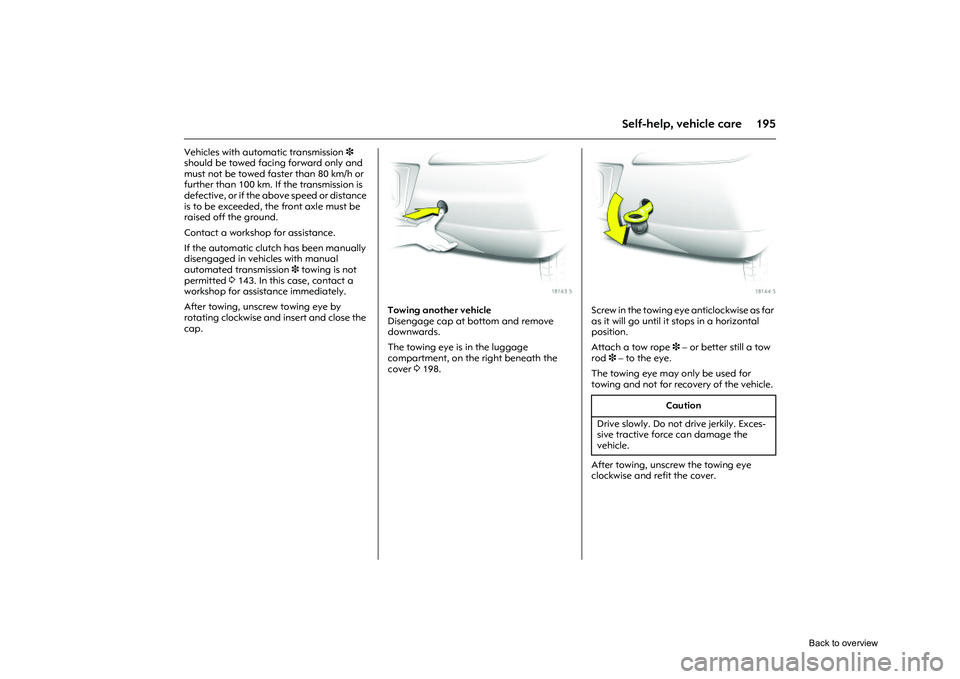
Picture no: 18143s.tif
Towing another vehicle
Disengage cap at bottom and remove
downwards.
The towing eye is in the luggage
compartment, on the right beneath the
cover 3198.
Picture no: 18144s.tif
Screw in the towing eye anticlockwise as far
as it will go until it stops in a horizontal
position.
Attach a tow rope 3 – or better still a tow
rod 3 – to the eye.
The towing eye may only be used for
towing and not for recovery of the vehicle.
After towing, unscrew the towing eye
clockwise and refit the cover.
Caution
Drive slowly. Do not drive jerkily. Exces-
sive tractive force can damage the
vehicle.
Back to overview
Page 202 of 284
196 Self-help, vehicle care
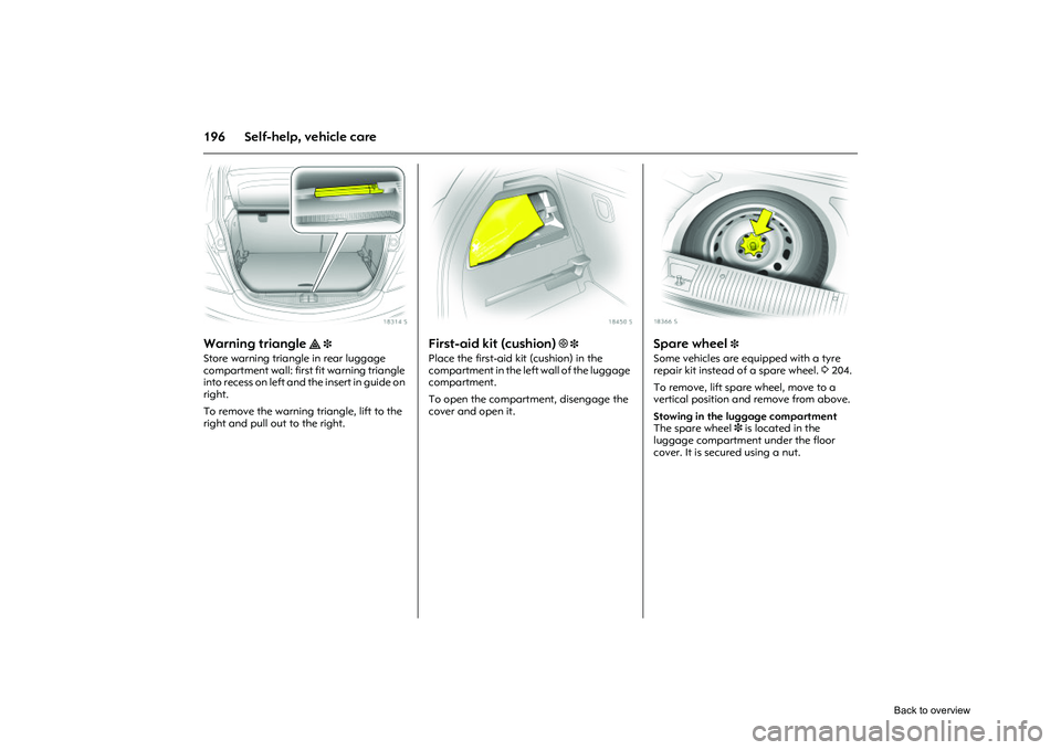
Picture no: 18314s.tif
Warning triangle
¨ 3
Store warning triangle in rear luggage
compartment wall: first fit warning triangle
into recess on left and the insert in guide on
right.
To remove the warning triangle, lift to the
right and pull out to the right.
Picture no: 18450s.tif
First-aid kit (cushion)
+ 3
Place the first-aid ki t (cushion) in the
compartment in the left wall of the luggage
compartment.
To open the compartment, disengage the
cover and open it.
Picture no: 18366s.tif
Spare wheel
3
Some vehicles are equipped with a tyre
repair kit instead of a spare wheel. 3204.
To remove, lift spare wheel, move to a
vertical position and remove from above.
Stowing in the luggage compartment
The spare wheel 3 is located in the
luggage compartment under the floor
cover. It is secured using a nut.
Back to overview
Page 209 of 284
203
Self-help, vehicle care
5. Unscrew the wheel bolts. If the wheel bolts have retaining
washers 3, they must not be removed.
6. Change wheel. Notes on spare wheel 3197. Notes on temporary spare wheel
3 197.
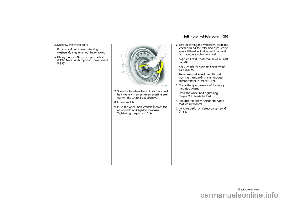
Picture no: 17249t.tif
7. Screw in the wheel bolts. Push the wheel
bolt wrench 3 on as far as possible and
tighten the wheel bolts slightly.
8. Lower vehicle.
9. Push the wheel bolt wrench 3 on as far
as possible and tighten crosswise.
Tightening torque is 110 Nm. 10. Before refitting the wheel trim, clean the
wheel around the retaining clips. Valve
symbol 3 on back of wheel trim must
point towards valve on wheel.
Align and refit wheel trim or wheel bolt
caps 3.
Alloy wheels 3: Align and refit wheel
bolt caps 3.
11. Stow removed wheel, tool kit and warning triangle 3 in the luggage
compartment 3196 to 3198.
12. Check the tyre pressure of the newly mounted wheel.
13. Have the wheel bolt tightening torque (110 Nm) checked.
14. Replace the faulty tyre on the wheel that was removed.
15. Initialise deflation detection system 3
3 164.
Back to overview