cooling OPEL CORSA E 2017.5 Manual user
[x] Cancel search | Manufacturer: OPEL, Model Year: 2017.5, Model line: CORSA E, Model: OPEL CORSA E 2017.5Pages: 269, PDF Size: 7.97 MB
Page 133 of 269

Climate control131Air vents
Adjustable air vents At least one air vent must be open
while the cooling is on.
Adjust the air amount at the vent
outlet by turning the adjuster wheel.
The vent is closed when the adjuster wheel is turned close to the left or
right.
Direct the flow of air by tilting and
swivelling the slats.
9 Warning
Do not attach any objects to the
slats of the air vents. Risk of
damage and injury in case of an
accident.
Fixed air vents
Additional air vents are located
beneath the windscreen and door windows and in the foot wells.
Maintenance
Air intake
The air intake in front of the
windscreen in the engine
compartment must be kept clear to
allow air intake. Remove any leaves,
dirt or snow.
Pollen filter The pollen filter cleans dust, soot,
pollen and spores from the air
entering the vehicle through the air
intake.
Page 134 of 269

132Climate controlAir conditioning regularoperation
In order to ensure continuously
efficient performance, cooling must
be operated for a few minutes once a
month, irrespective of the weather
and time of year. Operation with
cooling is not possible when the
outside temperature is too low.
Service For optimal cooling performance, it is recommended to annually check the
climate control system, starting
three years after initial vehicle
registration, including:
● functionality and pressure test
● heating functionality
● leakage check
● check of drive belts
● cleaning of condenser and evaporator drainage
● performance check
Note
Refrigerant R-134a contains
fluorinated greenhouse gases.
Page 141 of 269

Driving and operating139Parking9Warning
● Do not park the vehicle on an
easily ignitable surface. The
high temperature of the
exhaust system could ignite the
surface.
● Always apply the parking brake. Activate the manual
parking brake without pressing the release button. Apply as
firmly as possible on a downhill slope or uphill slope. Depress
brake pedal at the same time to
reduce operating force.
● Switch off the engine.
● If the vehicle is on a level surface or uphill slope, engage
first gear or set the selector
lever to position P before
removing the ignition key. On
an uphill slope, turn the front
wheels away from the kerb.
If the vehicle is on a downhill
slope, engage reverse gear or
set the selector lever to position
P before removing the ignition
key. Turn the front wheels
towards the kerb.
● Close the windows and the sunroof.
● Remove the ignition key from the ignition switch. Turn the
steering wheel until the
steering wheel lock is felt to
engage.
For vehicles with automatic
transmission, the key can only
be removed when the selector
lever is in position P.
For vehicles with manual
transmission automated, the
key can only be removed from
the ignition switch when the
parking brake is applied.
● Lock the vehicle.
● Activate the anti-theft alarm system.
● The engine cooling fans may run
after the engine has been
switched off 3 192.
Caution
After running at high engine
speeds or with high engine loads,
operate the engine briefly at a low load or run in neutral for
approx. 30 seconds before
switching off, in order to protect
the turbocharger.
Note
In the event of an accident with
airbag deployment, the engine is
switched off automatically if the
vehicle comes to a standstill within a
certain time.
Page 187 of 269

Driving and operating185Trailer hitch
General information
Only use towing equipment that has
been approved for your vehicle.
Entrust retrofitting of towing
equipment to a workshop. It may be
necessary to make changes that
affect the cooling system, heat
shields or other equipment.
The bulb outage detection function for trailer brake light cannot detect a
partial bulb outage, e.g. in case of four
times five watt bulbs, the function only detects lamp outage when only a
single five Watt lamp remains or none remain.
Fitting of towing equipment could
cover the opening of the towing eye.
If this is the case use the coupling ball
bar for towing. Always keep the
coupling ball bar in the vehicle when
not in use.Driving characteristics and
towing tips
Before attaching a trailer, lubricatethe coupling ball. However, do not do
so if a stabiliser, which acts on the coupling ball, is being used to reduce snaking movements.
For trailers with low driving stability
and caravan trailers with a permitted
gross vehicle weight of more than
1000 kg a speed of 80 km/h must not
be exceeded; the use of a stabiliser is
recommended.
If the trailer starts snaking, drive more slowly, do not attempt to correct the
steering and brake sharply if
necessary.
When driving downhill, drive in the
same gear as if driving uphill and
drive at a similar speed.
Adjust tyre pressure to the value
specified for full load 3 253.Trailer towing
Trailer loadsThe permissible trailer loads are
vehicle and engine-dependent
maximum values which must not be
exceeded. The actual trailer load is
the difference between the actual
gross weight of the trailer and the
actual coupling socket load with the
trailer coupled.
The permissible trailer loads are
specified in the vehicle documents. In general, they are valid for gradients
up to max. 12%
The permitted trailer loads apply up to the specified incline and up to an
altitude of 1000 metres above sea
level. Since engine power decreases
as altitude increases due to the air
becoming thinner, therefore reducing
climbing ability, the permissible gross
train weight also decreases by 10%
for every 1000 metres of additional
altitude. The gross train weight does
not have to be reduced when driving
on roads with slight inclines (less than
8%, e.g. motorways).
Page 194 of 269

192Vehicle careEnd-of-life vehicle recoveryInformation on end-of-life vehicle
recovery centres and the recycling of
end-of-life vehicles is available on our website. Only entrust this work to an
authorised recycling centre.
Gas vehicles must be recycled by a
service centre authorised for gas
vehicles.Vehicle checks
Performing work9 Warning
Only perform engine compartment
checks when the ignition is off.
The cooling fan may start
operating even if the ignition is off.
9 Danger
The ignition system and Xenon
headlights use extremely high
voltage. Do not touch.
Bonnet
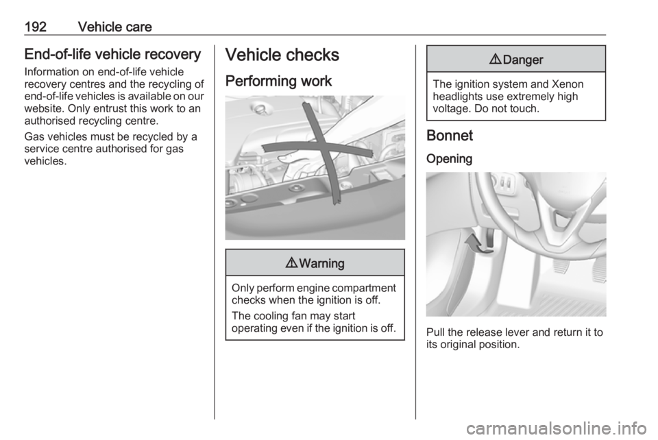
Opening
Pull the release lever and return it to
its original position.
Page 197 of 269

Vehicle care195
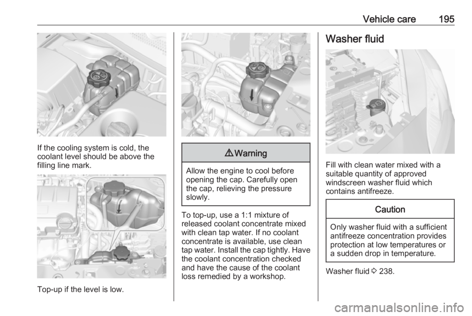
If the cooling system is cold, the
coolant level should be above the
filling line mark.
Top-up if the level is low.
9 Warning
Allow the engine to cool before
opening the cap. Carefully open
the cap, relieving the pressure
slowly.
To top-up, use a 1:1 mixture of released coolant concentrate mixed
with clean tap water. If no coolant
concentrate is available, use clean
tap water. Install the cap tightly. Have the coolant concentration checked
and have the cause of the coolant
loss remedied by a workshop.
Washer fluid
Fill with clean water mixed with a
suitable quantity of approved
windscreen washer fluid which
contains antifreeze.
Caution
Only washer fluid with a sufficient
antifreeze concentration provides
protection at low temperatures or
a sudden drop in temperature.
Washer fluid 3 238.
Page 212 of 269

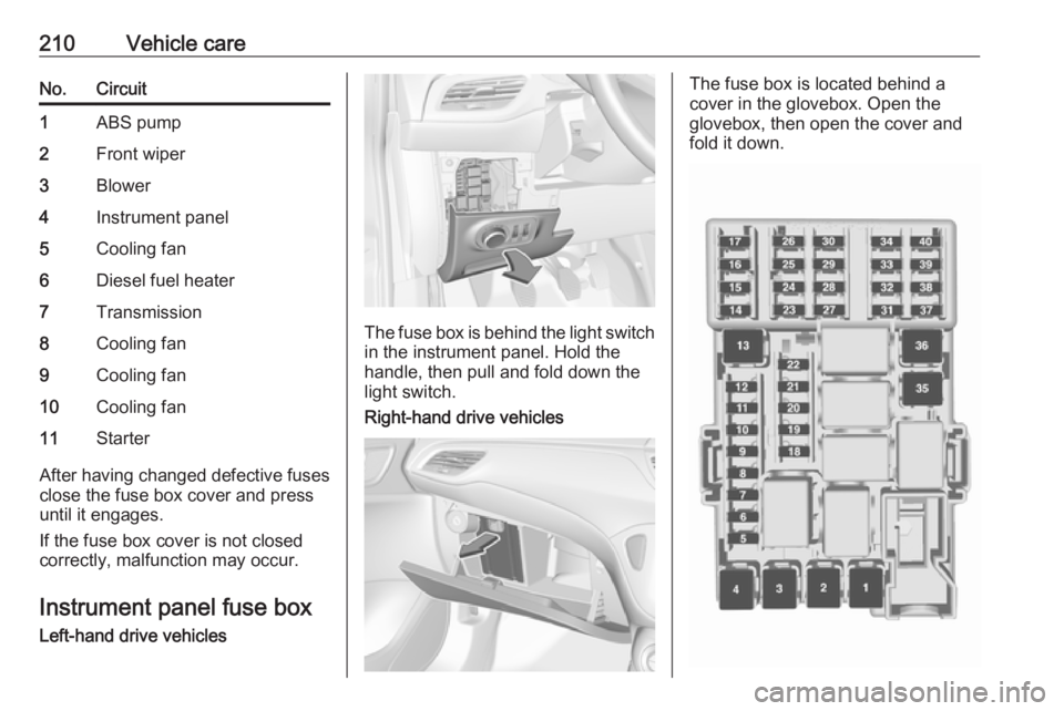
210Vehicle careNo.Circuit1ABS pump2Front wiper3Blower4Instrument panel5Cooling fan6Diesel fuel heater7Transmission8Cooling fan9Cooling fan10Cooling fan11Starter
After having changed defective fuses
close the fuse box cover and press
until it engages.
If the fuse box cover is not closed
correctly, malfunction may occur.
Instrument panel fuse box Left-hand drive vehicles
The fuse box is behind the light switch
in the instrument panel. Hold the
handle, then pull and fold down the
light switch.
Right-hand drive vehicles
The fuse box is located behind a
cover in the glovebox. Open the
glovebox, then open the cover and
fold it down.
Page 222 of 269

220Vehicle careIf the wheel covers and tyres used are
not factory approved, the tyres must
not have a rim protection ridge.
Wheel covers must not impair brake
cooling.9 Warning
Use of unsuitable tyres or wheel
covers could lead to sudden
pressure loss and thereby
accidents.
Steel wheels: When using locking
wheel nuts, do not attach wheel
covers.
Tyre chains
Tyre chains are only permitted on the
front wheels.
Always use fine mesh chains that add no more than 10 mm to the tyre tread
and the inboard sides (including chain lock).
9 Warning
Damage may lead to tyre blowout.
Tyre chains are permitted on tyres of
size 175/70 R14, 185/70 R14,
185/65 R15, 205/45 R17.
Tyre chains are permitted on tyres of
size 195/55 R16 with rims of size
16 x 6 and 16 x 6.5, the latter only in combination with limited steering
angle. Seek the assistance of a
workshop.
Tyre chains are not permitted on tyres of size 215/45 R17 and 215/40 R18.
The use of tyre chains is not permitted on the temporary spare wheel.
Tyre repair kit Minor damage to the tyre tread can be
repaired with the tyre repair kit.
Do not remove foreign bodies from
the tyres.
Tyre damage exceeding 4 mm or that is at the tyre's side wall near the rim
cannot be repaired with the tyre repair kit.9 Warning
Do not drive faster than 80 km/h.
Do not use for a lengthy period.
Steering and handling may be
affected.