lock OPEL CORSA E 2017.5 Manual user
[x] Cancel search | Manufacturer: OPEL, Model Year: 2017.5, Model line: CORSA E, Model: OPEL CORSA E 2017.5Pages: 269, PDF Size: 7.97 MB
Page 202 of 269
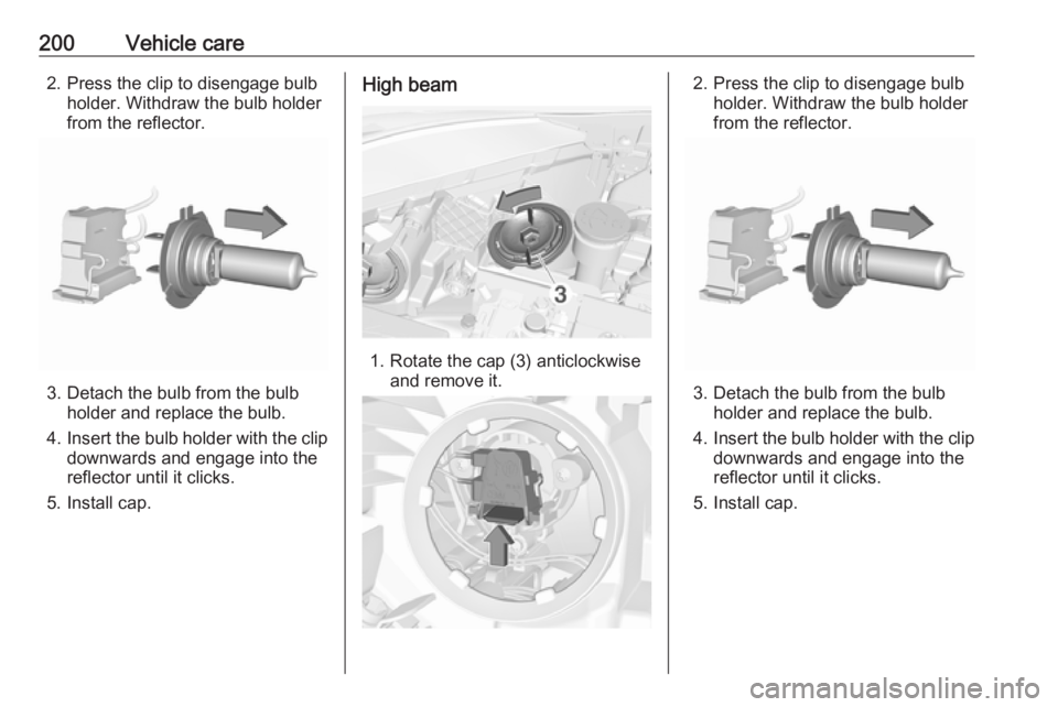
200Vehicle care2. Press the clip to disengage bulbholder. Withdraw the bulb holder
from the reflector.
3. Detach the bulb from the bulb holder and replace the bulb.
4. Insert the bulb holder with the clip
downwards and engage into the
reflector until it clicks.
5. Install cap.
High beam
1. Rotate the cap (3) anticlockwise and remove it.
2. Press the clip to disengage bulbholder. Withdraw the bulb holder
from the reflector.
3. Detach the bulb from the bulb holder and replace the bulb.
4. Insert the bulb holder with the clip
downwards and engage into the
reflector until it clicks.
5. Install cap.
Page 203 of 269
Vehicle care201Sidelight/daytime running light
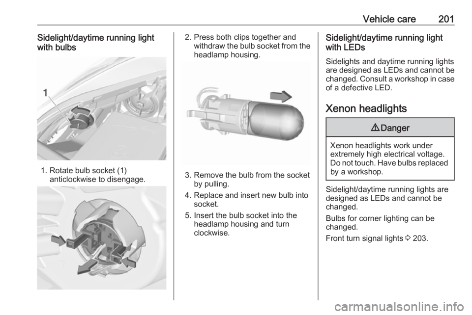
with bulbs
1. Rotate bulb socket (1) anticlockwise to disengage.
2. Press both clips together andwithdraw the bulb socket from theheadlamp housing.
3. Remove the bulb from the socket by pulling.
4. Replace and insert new bulb into socket.
5. Insert the bulb socket into the headlamp housing and turn
clockwise.
Sidelight/daytime running light
with LEDs
Sidelights and daytime running lights
are designed as LEDs and cannot be
changed. Consult a workshop in case
of a defective LED.
Xenon headlights9 Danger
Xenon headlights work under
extremely high electrical voltage.
Do not touch. Have bulbs replaced by a workshop.
Sidelight/daytime running lights are
designed as LEDs and cannot be
changed.
Bulbs for corner lighting can be
changed.
Front turn signal lights 3 203.
Page 204 of 269
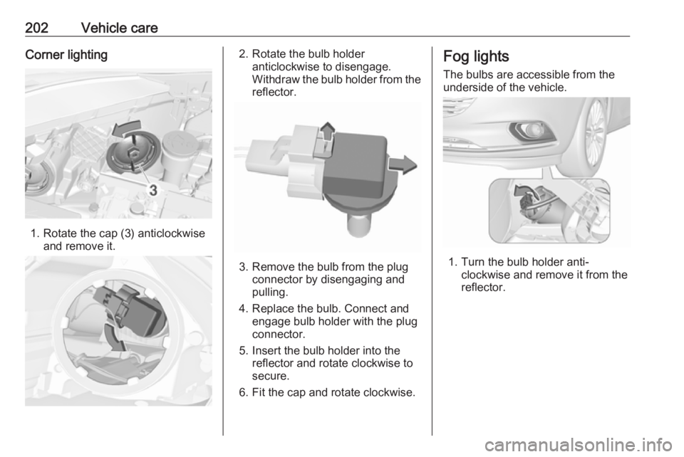
202Vehicle careCorner lighting
1. Rotate the cap (3) anticlockwiseand remove it.
2. Rotate the bulb holderanticlockwise to disengage.
Withdraw the bulb holder from the
reflector.
3. Remove the bulb from the plug connector by disengaging and
pulling.
4. Replace the bulb. Connect and engage bulb holder with the plug
connector.
5. Insert the bulb holder into the reflector and rotate clockwise to
secure.
6. Fit the cap and rotate clockwise.
Fog lights
The bulbs are accessible from the
underside of the vehicle.
1. Turn the bulb holder anti- clockwise and remove it from the
reflector.
Page 205 of 269
Vehicle care203
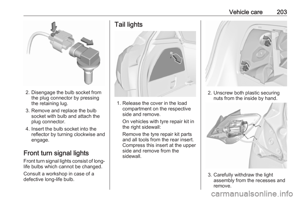
2. Disengage the bulb socket fromthe plug connector by pressing
the retaining lug.
3. Remove and replace the bulb socket with bulb and attach the
plug connector.
4. Insert the bulb socket into the reflector by turning clockwise and
engage.
Front turn signal lights
Front turn signal lights consist of long- life bulbs which cannot be changed.
Consult a workshop in case of a
defective long-life bulb.
Tail lights
1. Release the cover in the load compartment on the respective
side and remove.
On vehicles with tyre repair kit in
the right sidewall:
Remove the tyre repair kit parts
and all tools from the rear insert.
Compress this insert at the upper
side and remove from the
sidewall.
2. Unscrew both plastic securing nuts from the inside by hand.
3. Carefully withdraw the light assembly from the recesses and
remove.
Page 206 of 269
204Vehicle care
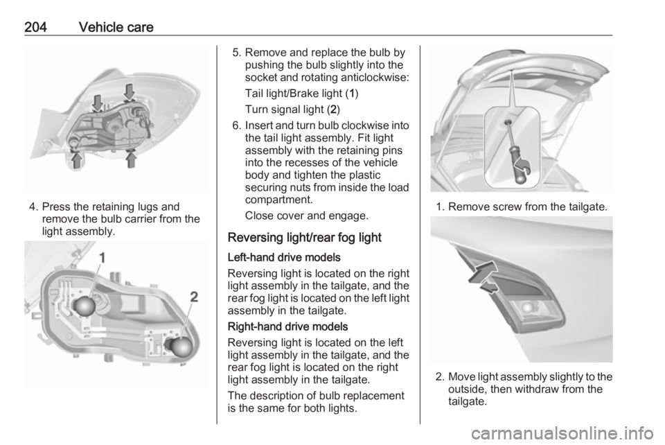
4. Press the retaining lugs andremove the bulb carrier from the
light assembly.
5. Remove and replace the bulb by pushing the bulb slightly into thesocket and rotating anticlockwise:
Tail light/Brake light ( 1)
Turn signal light ( 2)
6. Insert and turn bulb clockwise into
the tail light assembly. Fit light
assembly with the retaining pins
into the recesses of the vehicle
body and tighten the plastic
securing nuts from inside the load
compartment.
Close cover and engage.
Reversing light/rear fog light Left-hand drive models
Reversing light is located on the right
light assembly in the tailgate, and the rear fog light is located on the left light
assembly in the tailgate.
Right-hand drive models
Reversing light is located on the left
light assembly in the tailgate, and the
rear fog light is located on the right
light assembly in the tailgate.
The description of bulb replacement
is the same for both lights.
1. Remove screw from the tailgate.
2. Move light assembly slightly to the
outside, then withdraw from the
tailgate.
Page 207 of 269
Vehicle care205
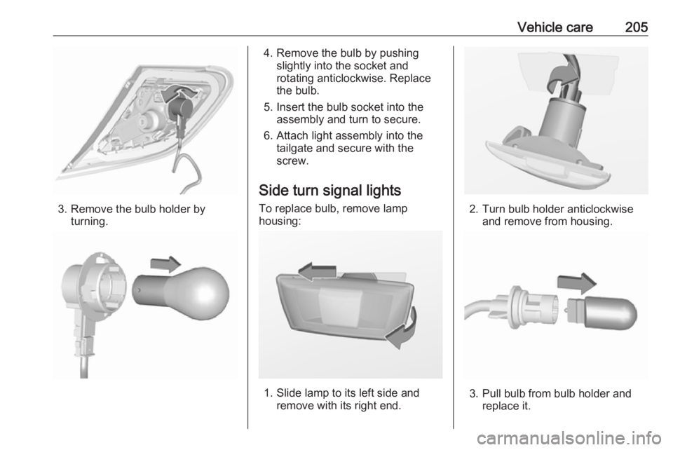
3. Remove the bulb holder byturning.
4. Remove the bulb by pushingslightly into the socket and
rotating anticlockwise. Replace
the bulb.
5. Insert the bulb socket into the assembly and turn to secure.
6. Attach light assembly into the tailgate and secure with the
screw.
Side turn signal lights
To replace bulb, remove lamp
housing:
1. Slide lamp to its left side and remove with its right end.
2. Turn bulb holder anticlockwiseand remove from housing.
3. Pull bulb from bulb holder and replace it.
Page 208 of 269

206Vehicle care4. Insert bulb holder and turnclockwise.
5. Insert left end of the lamp, slide to
the left and insert right end.
Centre high-mounted brake light
Have LEDs replaced by a workshop.
Number plate light
1. Insert screwdriver in recess of the
cover, press to the side and
release spring.
2. Remove lamp downwards, taking care not to pull on the cable.
3. Remove bulb holder from lamp housing by turning anticlockwise.
4. Pull bulb from bulb holder andreplace it.
5. Insert bulb holder into lamp housing and turn clockwise.
6. Insert lamp into bumper and let engage.
Interior lights
Courtesy light, reading lights Have bulbs replaced by a workshop.
Load compartment light
Have bulbs replaced by a workshop.
Dome light
Have bulbs replaced by a workshop.
Instrument panel
illumination
Have bulbs replaced by a workshop.
Page 222 of 269

220Vehicle careIf the wheel covers and tyres used are
not factory approved, the tyres must
not have a rim protection ridge.
Wheel covers must not impair brake
cooling.9 Warning
Use of unsuitable tyres or wheel
covers could lead to sudden
pressure loss and thereby
accidents.
Steel wheels: When using locking
wheel nuts, do not attach wheel
covers.
Tyre chains
Tyre chains are only permitted on the
front wheels.
Always use fine mesh chains that add no more than 10 mm to the tyre tread
and the inboard sides (including chain lock).
9 Warning
Damage may lead to tyre blowout.
Tyre chains are permitted on tyres of
size 175/70 R14, 185/70 R14,
185/65 R15, 205/45 R17.
Tyre chains are permitted on tyres of
size 195/55 R16 with rims of size
16 x 6 and 16 x 6.5, the latter only in combination with limited steering
angle. Seek the assistance of a
workshop.
Tyre chains are not permitted on tyres of size 215/45 R17 and 215/40 R18.
The use of tyre chains is not permitted on the temporary spare wheel.
Tyre repair kit Minor damage to the tyre tread can be
repaired with the tyre repair kit.
Do not remove foreign bodies from
the tyres.
Tyre damage exceeding 4 mm or that is at the tyre's side wall near the rim
cannot be repaired with the tyre repair kit.9 Warning
Do not drive faster than 80 km/h.
Do not use for a lengthy period.
Steering and handling may be
affected.
Page 228 of 269

226Vehicle care●Do not start the vehicle when it is
raised on the jack.
● Before screwing in the wheel bolts, clean them and lightly coat
the taper of each wheel bolt with
commercially available grease.9 Warning
Do not grease the thread of the
wheel bolt.
1. Steel wheels:
Pull off the wheel cover.
Alloy wheels with bolt caps: Disengage wheel bolt caps with a
screwdriver and remove. To
protect the wheel, place a soft
cloth between the screwdriver
and the alloy wheel.Alloy wheels with centre cap:
Insert extractor in the open slot of
the centre cap and withdraw the
cap from the wheel. Vehicle tools 3 212.
2. Install the wheel wrench ensuring
that it locates securely and loosen
each wheel bolt by half a turn.
The wheels might be protected by
locking wheel bolts. To loosen
these specific bolts, first attach
the adapter for the locking wheel
bolts onto the head of the bolt
before installing the wheel
wrench. The adapter is located in
the glovebox.
3. Ensure the jack is correctly positioned under the relevant
vehicle jacking point.
On versions with sill panelling or
retrofitted sill panelling, no jack
Page 229 of 269

Vehicle care227may be used. The vehicle may be
damaged.
4. Set the jack to the necessary height. Position it directly below
the jacking point in a manner that
prevents it from slipping.
Attach jack handle and with the
jack correctly aligned rotate handle until wheel is clear of theground.
5. Unscrew the wheel bolts.
6. Change the wheel.
7. Screw on the wheel bolts.
8. Lower vehicle.
9. Install the wheel wrench ensuring that it locates securely and tighten
each bolt in a crosswise
sequence. Tightening torque is
110 Nm.
10. Align the valve hole in the wheel cover of the steel wheel with the
tyre valve before installing.
Install wheel bolt caps or centre
cap on alloy wheel.
11. Install vehicle jacking point cover.
12. Stow and secure the replaced wheel, the vehicle tools 3 212 and
the adapter for the locking wheel
bolts 3 57.
13. Check the tyre pressure of the installed tyre and the wheel bolt
torque as soon as possible.
Have the defective tyre renewed or repaired as soon as possible.
Jacking position for lifting platform