ESP OPEL CORSA E 2017.5 Manual user
[x] Cancel search | Manufacturer: OPEL, Model Year: 2017.5, Model line: CORSA E, Model: OPEL CORSA E 2017.5Pages: 269, PDF Size: 7.97 MB
Page 5 of 269
Introduction3Vehicle specific dataPlease enter your vehicle's data on
the previous page to keep it easily
accessible. This information is
available in the sections "Service and
maintenance" and "Technical data"
as well as on the identification plate.
Introduction
Your vehicle is a designed
combination of advanced technology, safety, environmental friendliness
and economy.
This Owner's Manual provides you
with all the necessary information to
enable you to drive your vehicle
safely and efficiently.
Make sure your passengers are
aware of the possible risk of accident
and injury which may result from
improper use of the vehicle.
You must always comply with the
specific laws and regulations of the
country that you are in. These laws
may differ from the information in this Owner's Manual.
Disregarding the description given in
this manual may affect your warranty.When this Owner's Manual refers to a
workshop visit, we recommend your
Opel Service Partner.
For gas vehicles we recommend an
Opel Repairer authorised for
servicing gas vehicles.
All Opel Service Partners provide
first-class service at reasonable
prices. Experienced mechanics
trained by Opel work according to
specific Opel instructions.
The customer literature pack should
always be kept ready to hand in the
vehicle.
Using this manual ● This manual describes all options
and features available for this
model. Certain descriptions,
including those for display and
menu functions, may not apply to
your vehicle due to model
variant, country specifications,
special equipment or
accessories.
● The "In brief" section will give you
an initial overview.● The table of contents at the beginning of this manual and
within each section shows where the information is located.
● The index will enable you to search for specific information.
● This Owner's Manual depicts left-
hand drive vehicles. Operation is similar for right-hand drive
vehicles.
● The Owner's Manual uses the engine identifier code. The
corresponding sales designation
and engineering code can be
found in the section "Technical
data".
● Directional data, e.g. left or right, or front or back, always relate to
the direction of travel.
● Displays may not support your specific language.
● Display messages and interior labelling are written in bold
letters.
Page 26 of 269
24Keys, doors and windowsRadio remote control battery
replacement
Replace the battery as soon as the
range reduces.
Batteries do not belong in household
waste. They must be disposed of at
an appropriate recycling collection
point.
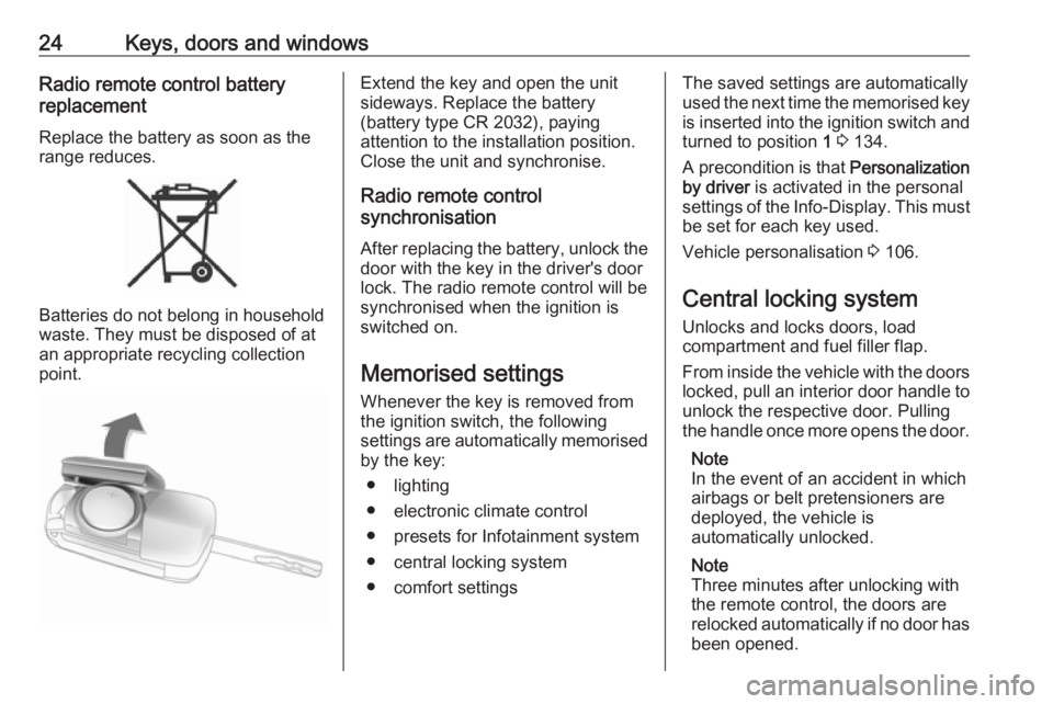
Extend the key and open the unit
sideways. Replace the battery
(battery type CR 2032), paying
attention to the installation position.
Close the unit and synchronise.
Radio remote control
synchronisation
After replacing the battery, unlock the
door with the key in the driver's door
lock. The radio remote control will be
synchronised when the ignition is
switched on.
Memorised settings
Whenever the key is removed from
the ignition switch, the following
settings are automatically memorised by the key:
● lighting
● electronic climate control
● presets for Infotainment system
● central locking system
● comfort settingsThe saved settings are automatically
used the next time the memorised key
is inserted into the ignition switch and
turned to position 1 3 134.
A precondition is that Personalization
by driver is activated in the personal
settings of the Info-Display. This must
be set for each key used.
Vehicle personalisation 3 106.
Central locking system Unlocks and locks doors, load
compartment and fuel filler flap.
From inside the vehicle with the doors locked, pull an interior door handle to
unlock the respective door. Pulling the handle once more opens the door.
Note
In the event of an accident in which
airbags or belt pretensioners are
deployed, the vehicle is
automatically unlocked.
Note
Three minutes after unlocking with
the remote control, the doors are
relocked automatically if no door has
been opened.
Page 34 of 269
32Keys, doors and windowsWindows
Windscreen Windscreen stickers
Do not attach stickers, e.g. toll road stickers or similar, on the windscreen
in the area of the interior mirror.
Otherwise the detection zone of the
sensor in the mirror housing could be restricted.
Windscreen replacementCaution
If the vehicle has a front-looking
camera sensor for the driver
assistance systems, it is very
important that any windscreen
replacement is performed
accurately according to Opel
specifications. Otherwise, these
systems may not work properly
and there is a risk of unexpected
behaviour and/or messages from
these systems.
Manual windows
The rear door windows can be
opened or closed manually with the
window cranks.
Power windows9 Warning
Take care when operating the
power windows. Risk of injury,
particularly to children.
Be careful when closing the
windows. Ensure that nothing
becomes trapped in them as they
move.
Operable with ignition on (position 2)
3 134.
Retained power off 3 135.
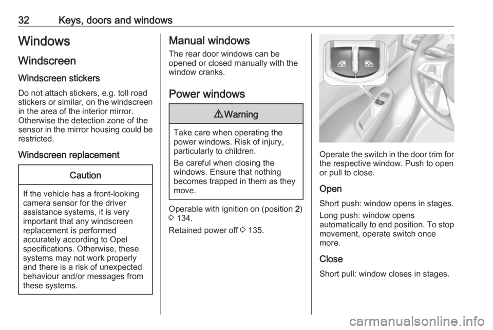
Operate the switch in the door trim for
the respective window. Push to open
or pull to close.
Open
Short push: window opens in stages. Long push: window opens
automatically to end position. To stop movement, operate switch once
more.
Close
Short pull: window closes in stages.
Page 43 of 269
Seats, restraints41Activate seat heating by pressing ß
for the respective front seat.
The LED in the button illuminates to
indicate activation.
Pressing ß once more deactivates
seat heating.
Seat heating is operational when engine is running.
During an Autostop, seat heating is
also operational.
Stop-start system 3 136.Seat belts
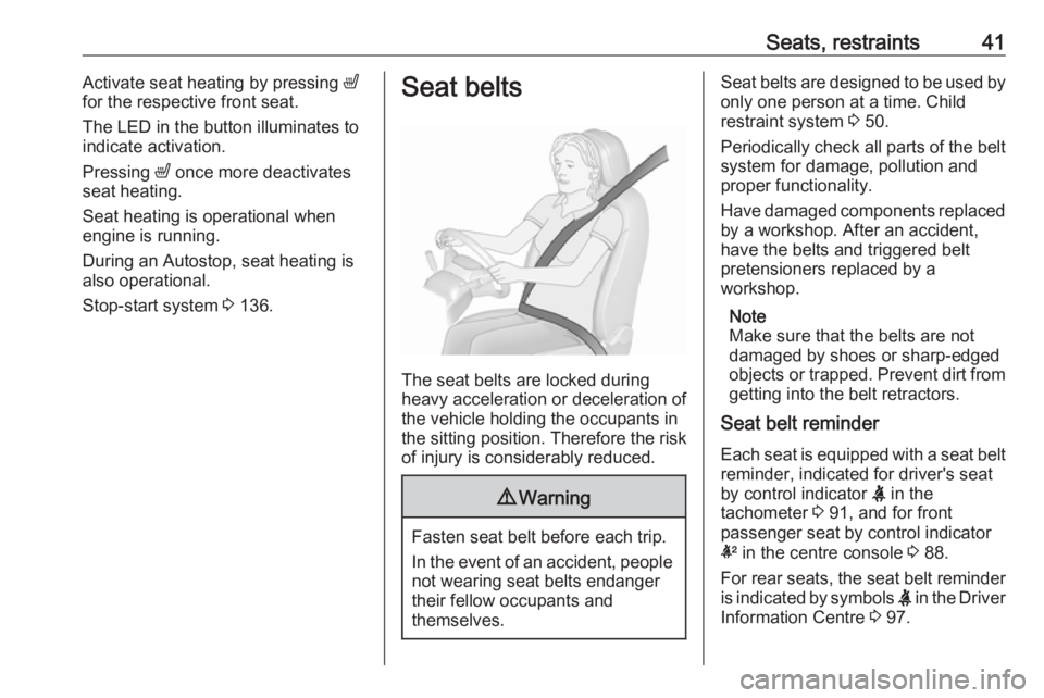
The seat belts are locked during
heavy acceleration or deceleration of
the vehicle holding the occupants in
the sitting position. Therefore the risk
of injury is considerably reduced.
9 Warning
Fasten seat belt before each trip.
In the event of an accident, people
not wearing seat belts endanger their fellow occupants and
themselves.
Seat belts are designed to be used by only one person at a time. Child
restraint system 3 50.
Periodically check all parts of the belt
system for damage, pollution and
proper functionality.
Have damaged components replaced by a workshop. After an accident,
have the belts and triggered belt
pretensioners replaced by a
workshop.
Note
Make sure that the belts are not
damaged by shoes or sharp-edged objects or trapped. Prevent dirt from getting into the belt retractors.
Seat belt reminder
Each seat is equipped with a seat belt reminder, indicated for driver's seat
by control indicator X in the
tachometer 3 91, and for front
passenger seat by control indicator
k in the centre console 3 88.
For rear seats, the seat belt reminder
is indicated by symbols X in the Driver
Information Centre 3 97.
Page 54 of 269

52Seats, restraintsChild restraint installation locations
Permissible options for fastening a child restraint system with a three-point seat belt
Weight class
On front passenger seat
On rear outboard seatsOn rear centre seat
activated airbagdeactivated airbagGroup 0: up to 10 kgXU 1,2U/L 3XGroup 0+: up to 13 kgXU1,2U/L 3XGroup I: 9 to 18 kgXU1,2U/L 3,4XGroup II: 15 to 25 kgU1,2XU/L 3,4XGroup III: 22 to 36 kgU1,2XU/L 3,4XU:universal suitability in conjunction with three-point seat beltL:suitable for particular child restraint systems of the 'specific-vehicle', 'restricted' or 'semi-universal' categories. The
child restraint system must be approved for the specific vehicle type (refer to the vehicle type list of the child restraint
system)X:no child restraint system permitted in this weight class1:move seat forwards as far as necessary and adjust seat backrest as far as necessary to a vertical position to ensure that the belt runs forwards from the upper anchorage point2:move seat upwards as far as necessary and adjust seat backrest as far as necessary to a vertical position to ensurethat the belt is tight on the buckle side3:move the respective front seat ahead of the child restraint system forwards as far as necessary4:adjust the respective backrest to the rearmost position 3 67 , adjust the respective headrest as necessary or remove
if required 3 36
Page 56 of 269

54Seats, restraintsX:no ISOFIX child restraint system approved for this weight class1:move seat forwards as far as necessary and adjust seat backrest as far as necessary to a vertical position to ensure
that the belt runs forwards from the upper anchorage point2:move seat upwards as far as necessary and adjust seat backrest as far as necessary to a vertical position to ensure
that the belt is tight on the buckle side3:move the respective front seat ahead of the child restraint system forwards as far as necessary4:adjust the respective backrest to the rearmost position 3 67, adjust the respective headrest as necessary or
remove if required 3 365:ISOFIX/Top-tether fastening points optional for the front passenger seat (not available for sport seats)
ISOFIX size class and seat device
A – ISO/F3:forward-facing child restraint system for children of maximum size in the weight class 9 to 18 kgB – ISO/F2:forward-facing child restraint system for smaller children in the weight class 9 to 18 kgB1 – ISO/F2X:forward-facing child restraint system for smaller children in the weight class 9 to 18 kgC – ISO/R3:rear-facing child restraint system for children of maximum size in the weight class up to 18 kgD – ISO/R2:rear-facing child restraint system for smaller children in the weight class up to 18 kgE – ISO/R1:rear-facing child restraint system for young children in the weight class up to 13 kg
Page 68 of 269

66Storage
Insert the strap retainer and pull
tightly downwards as far as possible.
Press release lever and slide in wheel recesses all the way as far as they will
go.
Disengage the locking lever on the
diagonal support and fold both pedal crank recesses down.
9 Warning
Risk of pinching.
Swivel first the right clamping lever
( 1 ) forwards, followed by the left
clamping lever ( 2), until they can be
engaged in their respective recesses.
Page 70 of 269
68StoragePull the release handle on both sides,
pull the backrest forwards to the
vertical position and engage.
When unlocking, a red marking
appears next to the release lever. The
backrest is properly engaged when
the red marks on both sides near the
release lever are no longer visible.
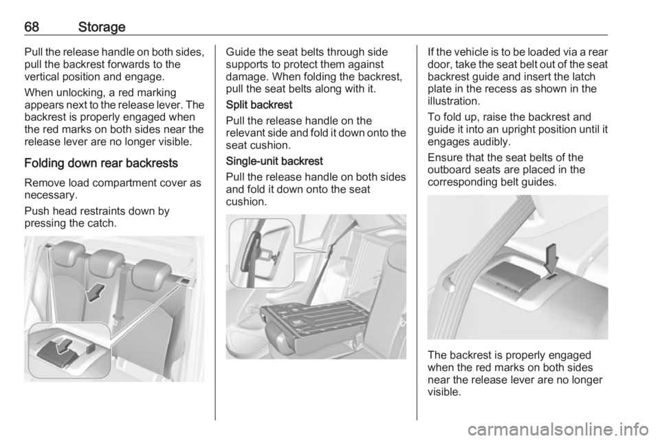
Folding down rear backrests Remove load compartment cover as
necessary.
Push head restraints down by
pressing the catch.Guide the seat belts through side
supports to protect them against
damage. When folding the backrest, pull the seat belts along with it.
Split backrest
Pull the release handle on the
relevant side and fold it down onto the seat cushion.
Single-unit backrest
Pull the release handle on both sides
and fold it down onto the seat
cushion.If the vehicle is to be loaded via a rear
door, take the seat belt out of the seat
backrest guide and insert the latch
plate in the recess as shown in the
illustration.
To fold up, raise the backrest and
guide it into an upright position until it engages audibly.
Ensure that the seat belts of the
outboard seats are placed in the corresponding belt guides.
The backrest is properly engaged
when the red marks on both sides
near the release lever are no longer
visible.
Page 72 of 269

70StorageTo remove rear cover, unhook
retaining strings from tailgate.
Lift cover at the rear and push it
upwards at the front. Remove the
cover.
To remove the three other segments
(order 1 to 3) lift at the rear,
disengage, twist and remove.
Fitting
Install the segments in the order 3 to
1. Engage segments in recesses at
the side.
The segments overlap at the
connecting points when they are
closed.
To install rear cover, engage cover in side guides and fold downwards.
Attach retaining strings to tailgate.
Rear floor storage cover
Rear floor cover
Lift up rear floor cover to gain access
to emergency breakdown equipment.
Tools 3 212.
In models with a tyre repair kit on the
right side in the load compartment,
the spare wheel recess may be used
as an additional stowage
compartment. Tyre repair kit 3 220.
Double load-bay floor
The double load-bay floor can be
inserted in the load compartment in
two positions:
● directly above the cover for the spare wheel recess or the floor
cover
● or in the upper openings in the load compartment
To remove, lift the load-bay floor
using the recess and pull backwards.
To insert, push the load-bay floor
forwards in the corresponding guide,
then lower.
Page 82 of 269
80Instruments and controlsIf outside temperature drops to 3 °C,
a warning message is displayed in the
Driver Information Centre.9 Warning
The road surface may already be
icy even though the display
indicates a few degrees above
0 °C.
Clock
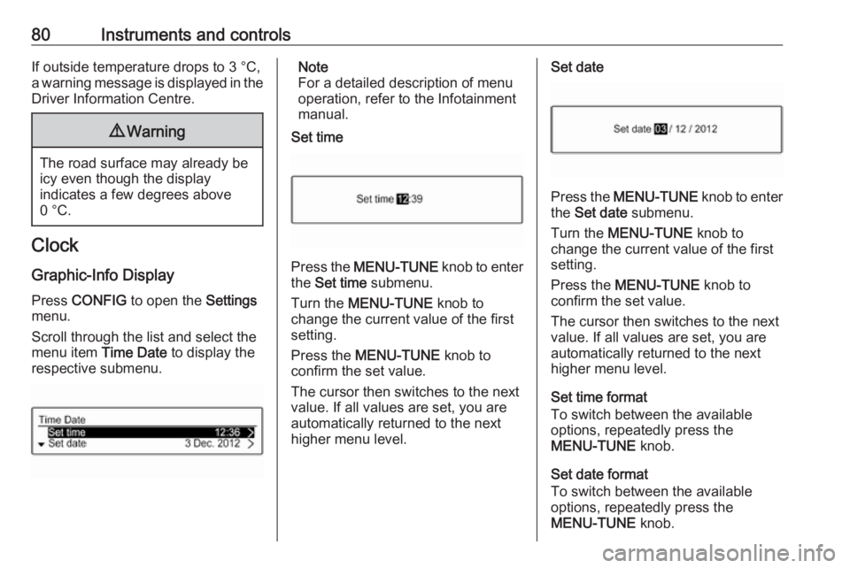
Graphic-Info Display Press CONFIG to open the Settings
menu.
Scroll through the list and select the
menu item Time Date to display the
respective submenu.
Note
For a detailed description of menu
operation, refer to the Infotainment
manual.
Set time
Press the MENU-TUNE knob to enter
the Set time submenu.
Turn the MENU-TUNE knob to
change the current value of the first setting.
Press the MENU-TUNE knob to
confirm the set value.
The cursor then switches to the next
value. If all values are set, you are
automatically returned to the next
higher menu level.
Set date
Press the MENU-TUNE knob to enter
the Set date submenu.
Turn the MENU-TUNE knob to
change the current value of the first setting.
Press the MENU-TUNE knob to
confirm the set value.
The cursor then switches to the next
value. If all values are set, you are
automatically returned to the next
higher menu level.
Set time format
To switch between the available
options, repeatedly press the
MENU-TUNE knob.
Set date format
To switch between the available
options, repeatedly press the
MENU-TUNE knob.