lock OPEL CORSA E 2018.5 Manual user
[x] Cancel search | Manufacturer: OPEL, Model Year: 2018.5, Model line: CORSA E, Model: OPEL CORSA E 2018.5Pages: 271, PDF Size: 7.99 MB
Page 63 of 271

Storage61Open out the lamp support on the
back of the tail lamp completely until
it engages.
Push the clamping lever down and
push the lamp support into the
retainer until it engages.
Perform this procedure for both tail
lamps.
Check the cable and lamp position to
ensure these are correctly installed
and are securely located.
Lock the rear carrier system
Swivel the left clamping lever ( 1) first,
followed by the right clamping lever
( 2 ) until they stop. Both clamping
levers must point backwards,
otherwise safe functionality is not
guaranteed.
Note
Close the tailgate.
Unfold pedal crank recesses
Fold one or both pedal crank
recesses upwards until the diagonal
support engages.
Page 68 of 271

66Storage
Insert the strap retainer and pull
tightly downwards as far as possible.
Press release lever and slide in wheel recesses all the way as far as they will
go.
Disengage the locking lever on the
diagonal support and fold both pedal crank recesses down.
9 Warning
Risk of pinching.
Swivel first the right clamping lever
( 1 ) forwards, followed by the left
clamping lever ( 2), until they can be
engaged in their respective recesses.
Page 69 of 271

Storage67Push the clamping lever down and
pull both lamp supports out of the recesses.
Fold in the lamp supports on the
backs of the tail lamps.
First place the front tail lamp ( 1), then
the rear tail lamp ( 2) in the recesses
and push down as far as possible. Push cables all the way into all guides
in order to prevent damage.
Open the tailgate.
Push the release lever up and hold.
Lift the system slightly and push it into the bumper until it engages.
Release lever must return to original
position.
9 Warning
If the system cannot be correctly
engaged, please seek the
assistance of a workshop.
Load compartment
Load compartment extension The rear backrest can be locked in
two positions. When transporting
bulky items, lock in an upright
position.
Split backrest
Pull the release handle on the
relevant side, pull the backrest
forwards to the vertical position and engage.
Single-unit backrest
Page 70 of 271

68StoragePull the release handle on both sides,
pull the backrest forwards to the
vertical position and engage.
When unlocking, a red marking
appears next to the release lever. The
backrest is properly engaged when
the red marks on both sides near the
release lever are no longer visible.
Folding down rear backrests Remove load compartment cover as
necessary.
Push head restraints down by
pressing the catch.Guide the seat belts through side
supports to protect them against
damage. When folding the backrest, pull the seat belts along with it.
Split backrest
Pull the release handle on the
relevant side and fold it down onto the seat cushion.
Single-unit backrest
Pull the release handle on both sides
and fold it down onto the seat
cushion.If the vehicle is to be loaded via a rear
door, take the seat belt out of the seat
backrest guide and insert the latch
plate in the recess as shown in the
illustration.
To fold up, raise the backrest and
guide it into an upright position until it engages audibly.
Ensure that the seat belts of the
outboard seats are placed in the corresponding belt guides.
The backrest is properly engaged
when the red marks on both sides
near the release lever are no longer
visible.
Page 71 of 271

Storage699Warning
Only drive the vehicle when the
backrests are securely locked into position. Otherwise there is a risk
of personal injury or damage to the
load or vehicle in the event of hard braking or a collision.
The seat belt of the centre seat could
be blocked when the backrest is
folded up too quickly. To unlock the
retractor, push in the seat belt or pull
it out by approx. 20 mm then release.
Load compartment cover
Do not place any objects on the cover.
3-door / 5-door hatchback
Removing
Unhook retaining strings from
tailgate.
Lift cover at the rear and push it
upwards at the front.
Remove the cover.
Stowing
When the load compartment is fully
loaded, stow the load compartment
cover on the rear seats or remove
from vehicle.
Fitting
Engage cover in side guides and fold
downwards. Attach retaining strings
to tailgate.
Delivery vanThe load compartment cover consists
of four segments which can be
individually removed and inserted.
Removing
Page 77 of 271

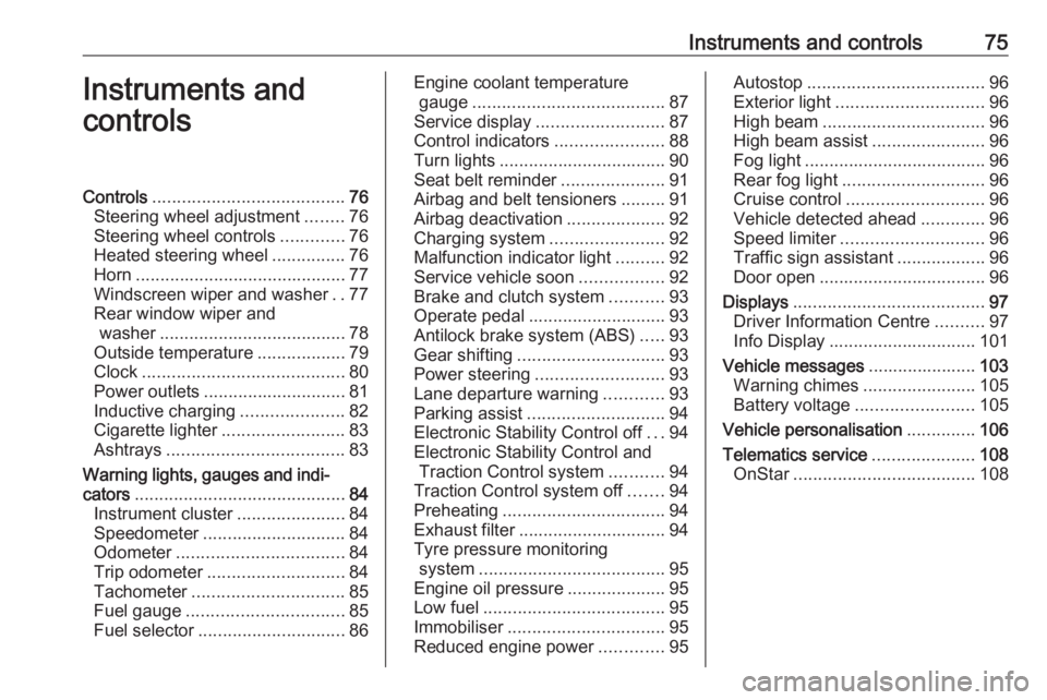
Instruments and controls75Instruments and
controlsControls ....................................... 76
Steering wheel adjustment ........76
Steering wheel controls .............76
Heated steering wheel ...............76
Horn ........................................... 77
Windscreen wiper and washer ..77
Rear window wiper and washer ...................................... 78
Outside temperature ..................79
Clock ......................................... 80
Power outlets ............................. 81
Inductive charging .....................82
Cigarette lighter ......................... 83
Ashtrays .................................... 83
Warning lights, gauges and indi‐ cators ........................................... 84
Instrument cluster ......................84
Speedometer ............................. 84
Odometer .................................. 84
Trip odometer ............................ 84
Tachometer ............................... 85
Fuel gauge ................................ 85
Fuel selector .............................. 86Engine coolant temperature
gauge ....................................... 87
Service display .......................... 87
Control indicators ......................88
Turn lights .................................. 90
Seat belt reminder .....................91
Airbag and belt tensioners .........91
Airbag deactivation ....................92
Charging system .......................92
Malfunction indicator light ..........92
Service vehicle soon .................92
Brake and clutch system ...........93
Operate pedal ............................ 93
Antilock brake system (ABS) .....93
Gear shifting .............................. 93
Power steering .......................... 93
Lane departure warning ............93
Parking assist ............................ 94
Electronic Stability Control off ...94
Electronic Stability Control and Traction Control system ...........94
Traction Control system off .......94
Preheating ................................. 94
Exhaust filter .............................. 94
Tyre pressure monitoring system ...................................... 95
Engine oil pressure ....................95
Low fuel ..................................... 95
Immobiliser ................................ 95
Reduced engine power .............95Autostop .................................... 96
Exterior light .............................. 96
High beam ................................. 96
High beam assist .......................96
Fog light ..................................... 96
Rear fog light ............................. 96
Cruise control ............................ 96
Vehicle detected ahead .............96
Speed limiter ............................. 96
Traffic sign assistant ..................96
Door open .................................. 96
Displays ....................................... 97
Driver Information Centre ..........97
Info Display .............................. 101
Vehicle messages ......................103
Warning chimes .......................105
Battery voltage ........................ 105
Vehicle personalisation ..............106
Telematics service .....................108
OnStar ..................................... 108
Page 78 of 271

76Instruments and controlsControlsSteering wheel adjustment
Unlock lever, adjust steering wheel,
then engage lever and ensure it is
fully locked.
Do not adjust steering wheel unless
vehicle is stationary and steering
wheel lock has been released.
Steering wheel controls
Cruise control and speed limiter are
operated via the controls on the left
side of the steering wheel.
Additionally, forward collision alert
can be set by using the controls on the
left side of the steering wheel.
Infotainment system can be operated
via the controls on the right side of the
steering wheel.
Driver assistance systems 3 154.
Further information is available in the
Infotainment manual.
Heated steering wheel
Activate heating by pressing *.
Activation is indicated by the LED in
the button.
Page 82 of 271

80Instruments and controlsIf outside temperature drops to 3 °C,
a warning message is displayed in the
Driver Information Centre.9 Warning
The road surface may already be
icy even though the display
indicates a few degrees above
0 °C.
Clock
Graphic Info Display Press CONFIG to open the Settings
menu.
Scroll through the list and select the
menu item Time Date to display the
respective submenu.
Note
For a detailed description of menu
operation, refer to the Infotainment
manual.
Set time
Press the MENU-TUNE knob to enter
the Set time submenu.
Turn the MENU-TUNE knob to
change the current value of the first setting.
Press the MENU-TUNE knob to
confirm the set value.
The cursor then switches to the next
value. If all values are set, you are
automatically returned to the next
higher menu level.
Set date
Press the MENU-TUNE knob to enter
the Set date submenu.
Turn the MENU-TUNE knob to
change the current value of the first setting.
Press the MENU-TUNE knob to
confirm the set value.
The cursor then switches to the next
value. If all values are set, you are
automatically returned to the next
higher menu level.
Set time format
To switch between the available
options, repeatedly press the
MENU-TUNE knob.
Set date format
To switch between the available
options, repeatedly press the
MENU-TUNE knob.
Page 83 of 271

Instruments and controls81RDS clock synchronization
The RDS signal of most VHF
transmitters automatically sets the
time. RDS time synchronisation can take a few minutes. Some
transmitters do not send a correct
time signal. In such cases, it is
recommended to switch off the
automatic time synchronisation.
To switch between the options On
and Off, repeatedly press the
MENU-TUNE knob.
Colour Info Display
Press ; then select Settings screen.
Select Time and Date to display the
respective submenu.
Set Time Format
To select the desired time format,
touch the screen buttons 12 h or 24 h .
Set Date Format To select the desired date format,
select Set Date Format and choose
between the available options in the
submenu.
Auto Set
To choose whether time and date are to be set automatically or manually,
select Auto Set .
For time and date to be set
automatically, select On - RDS.
For time and date to be set manually,
select Off - Manual . If Auto Set is set
to Off - Manual , the submenu items
Set Time and Set Date become
available.
Set time and date
To adjust the time and date settings, select Set Time or Set Date .
Touch + or - to adjust the settings.
Power outlets
A 12 V power outlet is located in the
centre console.
Do not exceed the maximum power
consumption of 120 W.
Page 92 of 271

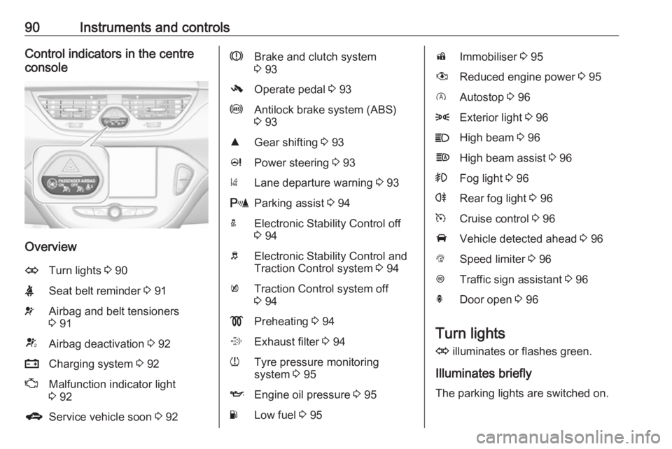
90Instruments and controlsControl indicators in the centre
console
Overview
OTurn lights 3 90XSeat belt reminder 3 91vAirbag and belt tensioners
3 91VAirbag deactivation 3 92pCharging system 3 92ZMalfunction indicator light
3 92gService vehicle soon 3 92RBrake and clutch system
3 93-Operate pedal 3 93uAntilock brake system (ABS)
3 93RGear shifting 3 93cPower steering 3 93)Lane departure warning 3 93rParking assist 3 94aElectronic Stability Control off
3 94bElectronic Stability Control and
Traction Control system 3 94kTraction Control system off
3 94!Preheating 3 94%Exhaust filter 3 94wTyre pressure monitoring
system 3 95IEngine oil pressure 3 95YLow fuel 3 95dImmobiliser 3 95#Reduced engine power 3 95DAutostop 3 968Exterior light 3 96CHigh beam 3 96fHigh beam assist 3 96>Fog light 3 96rRear fog light 3 96mCruise control 3 96AVehicle detected ahead 3 96LSpeed limiter 3 96LTraffic sign assistant 3 96hDoor open 3 96
Turn lights
O illuminates or flashes green.
Illuminates briefly The parking lights are switched on.