automatic transmission OPEL CORSA E 2019 Manual user
[x] Cancel search | Manufacturer: OPEL, Model Year: 2019, Model line: CORSA E, Model: OPEL CORSA E 2019Pages: 231, PDF Size: 6.87 MB
Page 126 of 231
124Driving and operating● The charging level of the vehiclebattery is below a defined level.
● The brake vacuum is not sufficient.
● The vehicle is driven at least at walking speed.
● The climate control system requests an engine start.
● The air conditioning is manually switched on.
If the bonnet is not fully closed, a
warning message is displayed in the
Driver Information Centre.
If an electrical accessory, e.g. a
portable CD player, is connected to
the power outlet, a brief power drop during restart might be noticeable.
Parking9 Warning
● Do not park the vehicle on an
easily ignitable surface. The
high temperature of the
exhaust system could ignite the
surface.
● Always apply the parking brake. Activate the manual
parking brake without pressing the release button. Apply as
firmly as possible on a downhill slope or uphill slope. Depress
brake pedal at the same time to
reduce operating force.
● Switch off the engine.
● If the vehicle is on a level surface or uphill slope, engage
first gear or set the selector
lever to position P before
removing the ignition key. On
an uphill slope, turn the front
wheels away from the kerb.
If the vehicle is on a downhill
slope, engage reverse gear or
set the selector lever to position
P before removing the ignition
key. Turn the front wheels
towards the kerb.
● Close the windows.
● Remove the ignition key from the ignition switch. Turn the
steering wheel until thesteering wheel lock is felt to
engage.
For vehicles with automatic
transmission, the key can only
be removed when the selector
lever is in position P.
● Lock the vehicle.
● Activate the anti-theft alarm system.
● The engine cooling fans may run
after the engine has been
switched off 3 158.
Caution
After running at high engine
speeds or with high engine loads,
operate the engine briefly at a low load or run in neutral for
approx. 30 seconds before
switching off, in order to protect
the turbocharger.
Page 129 of 231

Driving and operating127Automatic transmission
The automatic transmission permits
automatic gearshifting (automatic
mode) or manual gearshifting
(manual mode).
Manual shifting is possible in manual mode by pressing < or ] on the
selector lever 3 128.
Transmission display
The mode or selected gear is shown
in the Driver Information Centre.
In automatic mode, the driving
programme is indicated by D.
In manual mode, M and the number
of the selected gear is indicated.
R indicates reverse gear.
N indicates neutral position.
P indicates park position.
Selector leverP:park position, wheels are locked, engage only when the vehicle is
stationary and the parking brake
is appliedR:reverse gear, engage only when
the vehicle is stationaryN:neutralD:automatic shift modeM:manual shift mode<:push to upshift in manual mode]:push to downshift in manual
mode
The selector lever is locked in P and
can only be moved when the ignition
is on and the brake pedal is applied.
Without brake pedal applied, control
indicator j illuminates.
If the selector lever is not in P when
the ignition is switched off, control
indicator j flashes.
To engage P, R or M, press the
release button.
Page 131 of 231
Driving and operating129● Special programmesautomatically adapt the shifting
points when driving up inclines or down hills.
● When starting off in snowy or icy conditions or on other slippery
surfaces, the electronic
transmission control selects a
higher gear automatically.
Kickdown
Pressing down the accelerator pedal
beyond the kickdown detent will lead
to maximum acceleration
independent of selected driving
mode. The transmission shifts to a
lower gear depending on engine
speed.
Fault
In the event of a fault, control indicator
g illuminates. Additionally, a
message is displayed in the Driver
Information Centre.
Vehicle messages 3 89.
The transmission no longer shifts automatically. Continued travel is
possible with manual shifting.Only the highest gear is available.
Depending on the fault, second gear
may also be available in manual
mode. Shift only when the vehicle is
at a standstill.
Have the cause of the fault remedied
by a workshop.
Interruption of power supply In the event of an interruption of
power supply, the selector lever
cannot be moved out of the P
position. The ignition key cannot be
removed from the ignition switch.
If the vehicle battery is discharged,
start the vehicle using jump leads
3 195.
If the vehicle battery is not the cause
of the fault, release the selector lever.
1. Apply the parking brake.
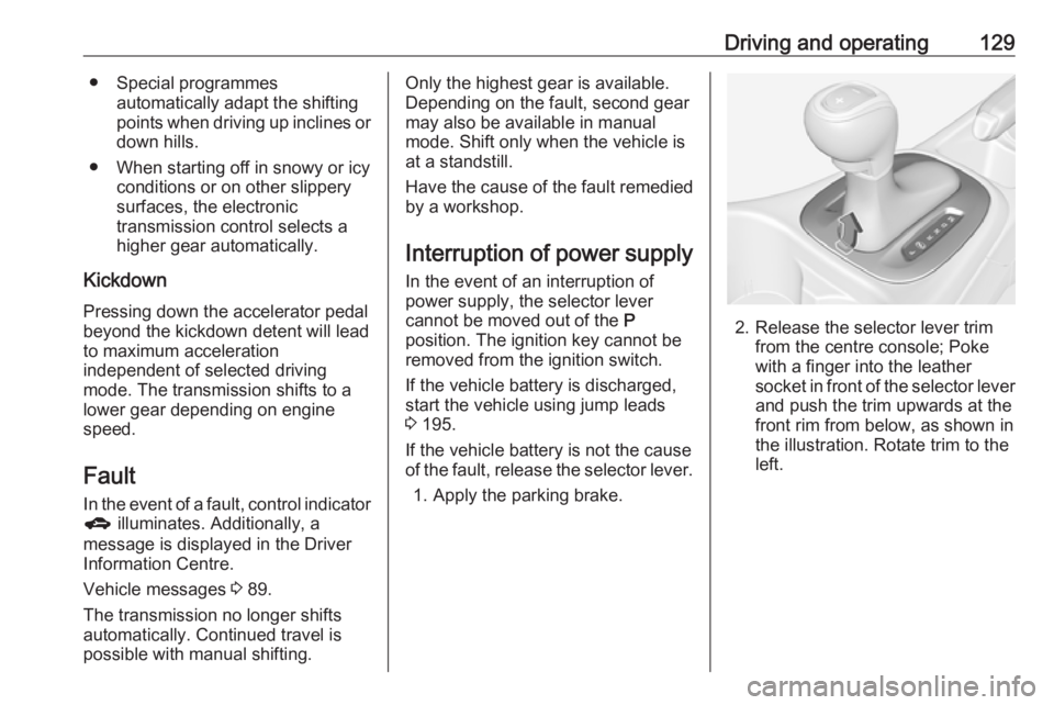
2. Release the selector lever trim from the centre console; Poke
with a finger into the leather
socket in front of the selector lever and push the trim upwards at the
front rim from below, as shown in
the illustration. Rotate trim to the
left.
Page 137 of 231

Driving and operating135system is necessary. This can occur
e.g. when turning the steering wheel
for one rotation with ignition switched
off. In this case, switch on ignition and
turn steering wheel once from lock to
lock.
If control indicators c and b do not
extinguish after calibration, seek the
assistance of a workshop.Driver assistance
systems9 Warning
Driver assistance systems are
developed to support the driver
and not to replace the driver's
attention.
The driver accepts full
responsibility when driving the
vehicle.
When using driver assistance
systems, always take care
regarding the current traffic
situation.
Cruise control
The cruise control can store and
maintain speeds of approx. 30 km/h
to maximum vehicle speed.
Deviations from the stored speeds
may occur when driving uphill or
downhill.
For safety reasons, the cruise control cannot be activated until the brake
pedal has been operated once.
Activating in first gear is not possible.
Do not use the cruise control if it is not advisable to maintain a constant
speed.
On vehicles with automatic
transmission cruise control can be
activated in automatic mode and
manual mode.
Control indicator m 3 83.
Page 179 of 231
Vehicle care177No.Circuit34–35Tyre repair kit36–37Rear wiper38Cigarette lighter39Power windows, automatic
transmission display40–Vehicle tools
Tools
Vehicles without spare wheel
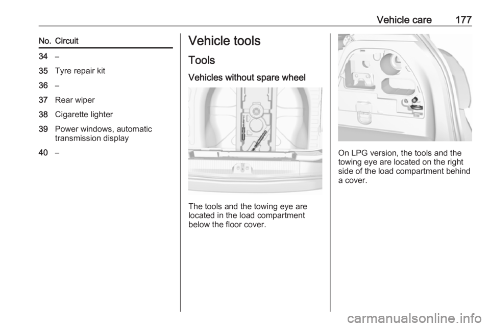
The tools and the towing eye are
located in the load compartment below the floor cover.
On LPG version, the tools and the
towing eye are located on the right
side of the load compartment behind
a cover.
Page 184 of 231
182Vehicle careThe use of commercially-availableliquid tyre repair kits can impair the
function of the system. Factory-
approved repair kits can be used.
Operating electronic devices or being close to facilities using similar wave
frequencies could disrupt the tyre
pressure monitoring system.
Each time the tyres are replaced, tyre
pressure monitoring system sensors
must be dismounted and serviced. For the screwed sensor; replace
valve core and sealing ring. For the
clipped sensor; replace complete
valve stem.
Vehicle loading status
Adjust tyre pressure to load condition according to the tyre information labelor tyre pressure chart 3 214, and
select the appropriate setting in the menu Tyre Load in the Driver
Information Centre, Vehicle
Information Menu 3 83 . This setting is
the reference for the tyre pressure
warnings.
The menu Tyre Load only appears
when the vehicle is at a standstill and
the parking brake is applied.On vehicles with automatic
transmission, the selector lever must
be in P.
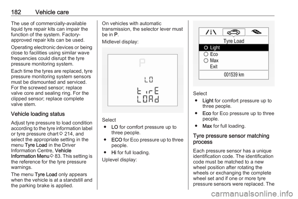
Midlevel display:
Select ● LO for comfort pressure up to
three people.
● ECO for Eco pressure up to three
people.
● Hi for full loading.
Uplevel display:
Select ● Light for comfort pressure up to
three people.
● Eco for Eco pressure up to three
people.
● Max for full loading.
Tyre pressure sensor matching
process
Each pressure sensor has a unique identification code. The identification
code must be matched to a new
wheel position after rotating the
wheels or exchanging the complete
wheel set and if one or more tyre
pressure sensors were replaced. The
Page 185 of 231
Vehicle care183tyre pressure sensor matching
process should also be performed
after replacing a spare wheel with a
road wheel containing a tyre pressure
sensor.
The malfunction light w and the
warning message or code should
extinguish at the next ignition cycle. The sensors are matched to the
wheel positions, using a relearn tool,
in the following order: left side front
wheel, right side front wheel, right
side rear wheel and left side rear
wheel. The turn light at the current
active position is illuminated until
sensor is matched.
Consult a workshop for service. There
are 2 minutes to match the first wheel position, and 5 minutes overall to
match all four wheel positions. If it
takes longer, the matching process
stops and must be restarted.
The tyre pressure sensor matching
process is:
1. Apply the parking brake.
2. Turn the ignition on.3. On vehicles with automatic transmission: set the selector
lever to P.
On vehicles with manual
transmission: select neutral.
4. Use MENU on the stalk to select
the Vehicle Information
Menu ? in the Driver
Information Centre.
5. Turn the adjuster wheel to scroll to
the tyre pressure menu.
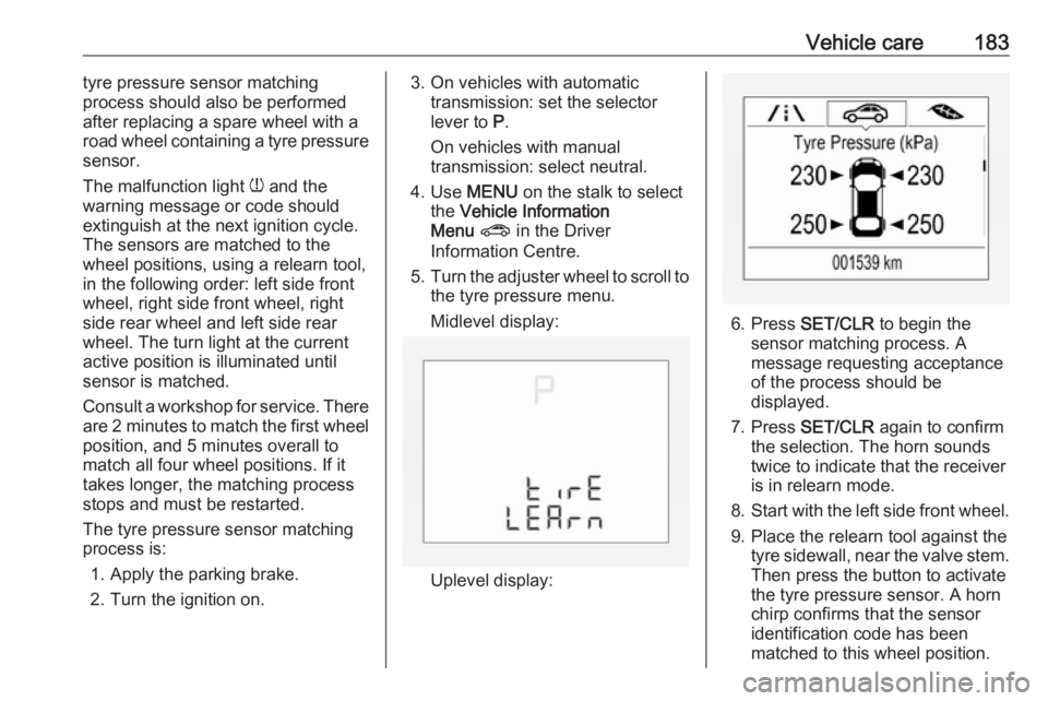
Midlevel display:
Uplevel display:
6. Press SET/CLR to begin the
sensor matching process. A
message requesting acceptance
of the process should be
displayed.
7. Press SET/CLR again to confirm
the selection. The horn sounds
twice to indicate that the receiver
is in relearn mode.
8. Start with the left side front wheel.
9. Place the relearn tool against the tyre sidewall, near the valve stem.Then press the button to activate
the tyre pressure sensor. A horn
chirp confirms that the sensor
identification code has been
matched to this wheel position.
Page 197 of 231

Vehicle care195Jump starting
Do not start with a quick charger.
A vehicle with a discharged vehicle
battery can be started using jump
leads and the vehicle battery of
another vehicle.9 Warning
Be extremely careful when starting
with jump leads. Any deviation
from the following instructions can
lead to injuries or damage caused
by battery explosion or damage to the electrical systems of both
vehicles.
9 Warning
Avoid contact of the battery with
eyes, skin, fabrics and painted
surfaces. The fluid contains
sulphuric acid which can cause
injuries and damage in the event
of direct contact.
● Never expose the battery to naked flames or sparks.
● A discharged vehicle battery canalready freeze at a temperature
of 0 °C. Defrost the frozen battery
before connecting jump leads.
● Wear eye protection and protective clothing when
handling a battery.
● Use a booster battery with the same voltage (12 V). Its capacity
(Ah) must not be much less than
that of the discharged vehicle battery.
● Use jump leads with insulated terminals and a cross section of
at least 16 mm 2
.
● Do not disconnect the discharged
vehicle battery from the vehicle.
● Switch off all unnecessary electrical consumers.
● Do not lean over the battery during jump starting.
● Do not allow the terminals of one
lead to touch those of the other
lead.
● The vehicles must not come into contact with each other during
the jump starting process.● Apply the parking brake, transmission in neutral,
automatic transmission in P.
● Open the positive terminal protection caps of both vehicle
batteries.
Lead connection order:
1. Connect the red lead to the positive terminal of the booster
vehicle battery.
2. Connect the other end of the red lead to the positive terminal of the
discharged vehicle battery.
Page 199 of 231
Vehicle care197
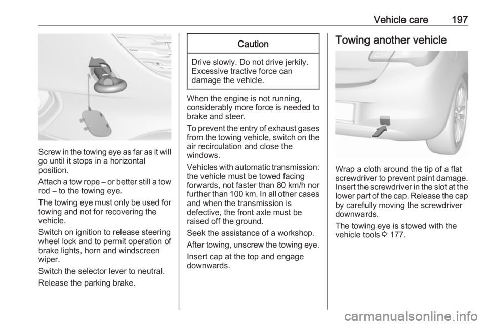
Screw in the towing eye as far as it will
go until it stops in a horizontal
position.
Attach a tow rope – or better still a tow
rod – to the towing eye.
The towing eye must only be used for towing and not for recovering the
vehicle.
Switch on ignition to release steering
wheel lock and to permit operation of
brake lights, horn and windscreen
wiper.
Switch the selector lever to neutral.
Release the parking brake.
Caution
Drive slowly. Do not drive jerkily.
Excessive tractive force can
damage the vehicle.
When the engine is not running,
considerably more force is needed to
brake and steer.
To prevent the entry of exhaust gases from the towing vehicle, switch on the
air recirculation and close the
windows.
Vehicles with automatic transmission: the vehicle must be towed facing
forwards, not faster than 80 km/h nor further than 100 km. In all other cases
and when the transmission is
defective, the front axle must be
raised off the ground.
Seek the assistance of a workshop.
After towing, unscrew the towing eye.
Insert cap at the top and engage
downwards.
Towing another vehicle
Wrap a cloth around the tip of a flat
screwdriver to prevent paint damage. Insert the screwdriver in the slot at the
lower part of the cap. Release the cap by carefully moving the screwdriver
downwards.
The towing eye is stowed with the
vehicle tools 3 177.
Page 226 of 231
224IndexAAccessories and vehicle modifications .......................... 156
Adjustable air vents ...................117
Airbag and belt tensioners ...........78
Airbag deactivation ................47, 79
Airbag label................................... 42 Airbag system .............................. 42
Air conditioning regular operation ................................ 118
Air conditioning system .............. 111
Air intake .................................... 118
Air vents...................................... 117
Antilock brake system ................ 131
Antilock brake system (ABS) .......80
Anti-theft alarm system ................27
Anti-theft locking system .............. 27
Appearance care ........................198
Ashtrays ....................................... 70
Automatic anti-dazzle ..................30
Automatic light control ...............101
Automatic locking ........................25
Automatic transmission .............127
Autostop ............................... 82, 122
B Battery discharge protection ......108
Battery voltage ............................. 92
Belts.............................................. 39
Bonnet ....................................... 158Brake and clutch fluid.................203
Brake and clutch system .............79
Brake assist ............................... 132
Brake fluid .................................. 161 Brakes ............................... 131, 161
Breakdown.................................. 196
Bulb replacement ....................... 164
C Capacities .................................. 212
Catalytic converter .....................126
Central locking system ................23
Centre high-mounted brake light 171
Changing tyre and wheel size ...184
Charging system .......................... 79
Child locks ................................... 25
Child restraint installation locations ................................... 52
Child restraints.............................. 48
Child restraint systems ................48
Cigarette lighter ........................... 70
City mode ................................... 134
Climate control ............................. 17
Climate control systems .............110
Clock ............................................ 68
Code ............................................. 89
Control indicators.......................... 75
Control of the vehicle .................119
Controls ........................................ 64
Convex shape .............................. 29