warning OPEL CORSA E 2019 Manual user
[x] Cancel search | Manufacturer: OPEL, Model Year: 2019, Model line: CORSA E, Model: OPEL CORSA E 2019Pages: 231, PDF Size: 6.87 MB
Page 49 of 231
Seats, restraints47Curtain airbag system
The curtain airbag system consists of an airbag in the roof frame on each
side. The location is identified by the
word AIRBAG on the roof pillars.
The curtain airbag system is triggered in the event of a side-on impact of a
certain severity. The ignition must be
switched on.
The inflated airbags cushion the
impact, thereby reducing the risk of
injury to the head in the event of a
side-on impact considerably.
9 Warning
Keep the area in which the airbag
inflates clear of obstructions.
The hooks on the handles in the
roof frame are only suitable for
hanging up light articles of
clothing, without coat hangers. Do not keep any items in these
clothes.
Airbag deactivation
The front passenger airbag system must be deactivated for a child
restraint system on the passenger
seat according to the instructions in
the tables 3 52.
The other airbag systems, the belt
pretensioners and all driver airbag
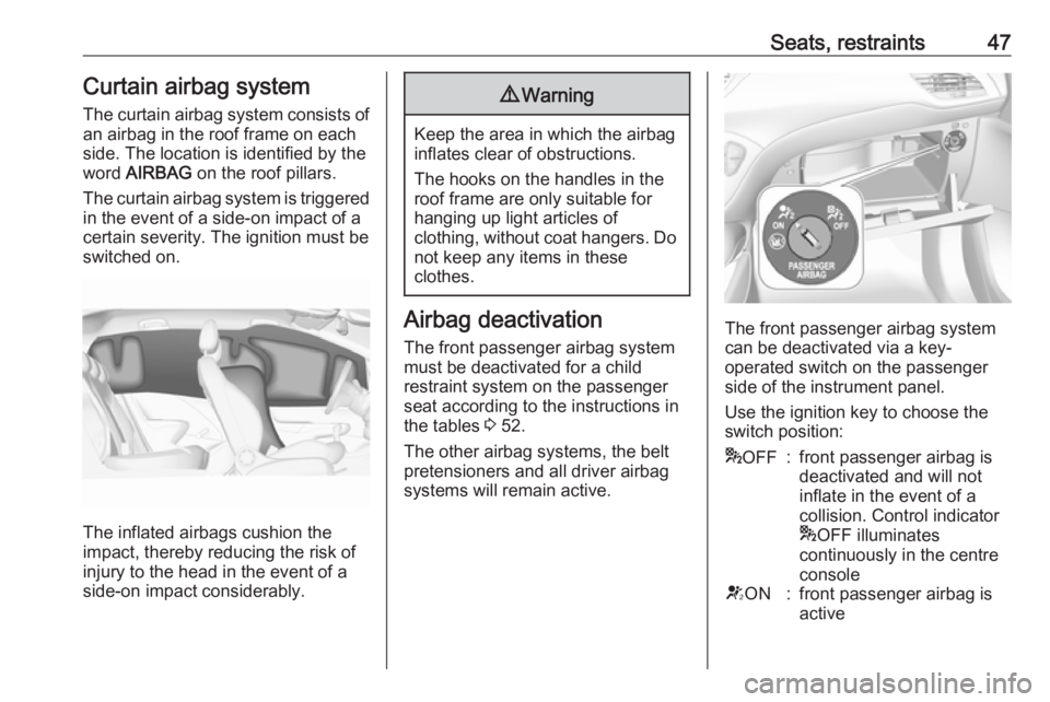
systems will remain active.The front passenger airbag system can be deactivated via a key-
operated switch on the passenger
side of the instrument panel.
Use the ignition key to choose the
switch position:
* OFF:front passenger airbag is
deactivated and will not
inflate in the event of a
collision. Control indicator
* OFF illuminates
continuously in the centre
consoleV ON:front passenger airbag is
active
Page 57 of 231
Storage55StorageStorage compartments................55
Glovebox ................................... 55
Cupholders ................................ 55
Front storage ............................. 56
Underseat storage .....................57
Load compartment .......................57
Load compartment cover ...........59
Rear floor storage cover ............59
Lashing eyes ............................. 60
Warning triangle ........................60
First aid kit ................................. 61
Roof rack system .........................61
Roof rack ................................... 61
Loading information .....................61Storage compartments9Warning
Do not store heavy or sharp
objects in the storage
compartments. Otherwise, the
storage compartment lid could
open and vehicle occupants could be injured by objects being thrown
around in the event of hard
braking, a sudden change in
direction or an accident.
Glovebox
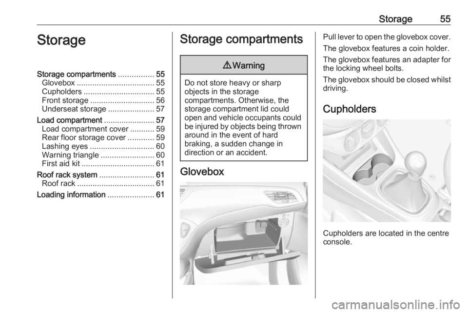
Pull lever to open the glovebox cover.
The glovebox features a coin holder.
The glovebox features an adapter for
the locking wheel bolts.
The glovebox should be closed whilst driving.
Cupholders
Cupholders are located in the centre
console.
Page 60 of 231

58StorageGuide the seat belts through side
supports to protect them against
damage. When folding the backrest,
pull the seat belts along with it.
Split backrest
Pull the release handle on the
relevant side and fold it down onto the seat cushion.
Single-unit backrest
Pull the release handle on both sides
and fold it down onto the seat
cushion.If the vehicle is to be loaded via a rear
door, take the seat belt out of the seat
backrest guide and insert the latch
plate in the recess as shown in the
illustration.
To fold up, raise the backrest and
guide it into an upright position until it engages audibly.
Ensure that the seat belts of the
outboard seats are placed in the corresponding belt guides.
The backrest is properly engaged
when the red marks on both sides
near the release lever are no longer
visible.
9 Warning
Only drive the vehicle when the
backrests are securely locked into position. Otherwise there is a risk
of personal injury or damage to the
load or vehicle in the event of hard braking or a collision.
The seat belt of the centre seat could
be blocked when the backrest is
folded up too quickly. To unlock the
retractor, push in the seat belt or pull
it out by approx. 20 mm then release.
Page 62 of 231
60Storage
● directly above the cover for thespare wheel recess or the floor
cover
● or in the upper openings in the load compartment
To remove, lift the load-bay floor
using the recess and pull backwards.
To insert, push the load-bay floor
forwards in the corresponding guide,
then lower.
If mounted in the upper position, the
space between the load-bay floor and
the spare wheel well cover can be
used as a stowage compartment.
In this position, if the rear seat
backrests are folded forwards, an
almost completely flat load bay is
created.
The double load-bay floor is able to
withstand a load of no more than
100 kg. In the lower position, the
double load-bay floor is able to
withstand the maximum permissible
load.
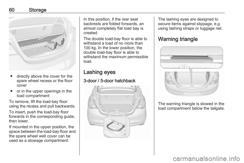
Lashing eyes 3-door / 5-door hatchbackThe lashing eyes are designed to
secure items against slippage, e.g.
using lashing straps or luggage net.
Warning triangle
The warning triangle is stowed in the
load compartment below the tailgate.
Page 64 of 231
62Storage●Use the hook at the right sidewall
of the load compartment for
hanging up carrier bags.
Maximum load: 5 kg.
● Do not allow the load to protrude above the upper edge of the
backrests.
● Do not place any objects on the load compartment cover or theinstrument panel.
● Do not cover the sensor on top of
the instrument panel.
● The load must not obstruct the operation of the pedals, parking
brake and gear selector lever, or
hinder the freedom of movement of the driver. Do not place any
unsecured objects in the interior.
● Do not drive with an open load compartment.9Warning
Always make sure that the load in
the vehicle is securely stowed.
Otherwise objects can be thrown
around inside the vehicle and
cause personal injury or damage
to the load or vehicle.
● The payload is the difference between the permitted gross
vehicle weight (see identification
plate 3 206) and the EC kerb
weight.
To calculate the payload, enter
the data for your vehicle in the
weights table at the front of this
manual.
The EC kerb weight includes
weights for the driver (68 kg),
luggage (7 kg) and all fluids (fuel
tank 90% full).
Optional equipment and
accessories increase the kerb
weight.
● Driving with a roof load increases
the sensitivity of the vehicle to
cross-winds and has a
detrimental effect on vehicle
handling due to the vehicle's
higher centre of gravity.
Distribute the load evenly and secure it properly with retaining
straps. Adjust the tyre pressure
and vehicle speed according to
the load conditions. Check and
retighten the straps frequently.
Do not drive faster than
120 km/h.
The permissible roof load is
75 kg. The roof load is the
combined weight of the roof rack and the load.
Page 65 of 231
Instruments and controls63Instruments and
controlsControls ....................................... 64
Steering wheel adjustment ........64
Steering wheel controls .............64
Heated steering wheel ...............64
Horn ........................................... 65
Windscreen wiper and washer ..65
Rear window wiper and washer ...................................... 66
Outside temperature ..................67
Clock ......................................... 68
Power outlets ............................. 69
Cigarette lighter ......................... 70
Ashtrays .................................... 70
Warning lights, gauges and indi‐ cators ........................................... 71
Instrument cluster ......................71
Speedometer ............................. 71
Odometer .................................. 71
Trip odometer ............................ 71
Tachometer ............................... 72
Fuel gauge ................................ 72
Fuel selector .............................. 73
Engine coolant temperature gauge ....................................... 74Service display.......................... 74
Control indicators ......................75
Turn lights .................................. 77
Seat belt reminder .....................78
Airbag and belt tensioners .........78
Airbag deactivation ....................79
Charging system .......................79
Malfunction indicator light ..........79
Service vehicle soon .................79
Brake and clutch system ...........79
Operate pedal ............................ 80
Antilock brake system (ABS) .....80
Gear shifting .............................. 80
Power steering .......................... 80
Lane departure warning ............80
Parking assist ............................ 80
Electronic Stability Control and Traction Control system ...........81
Exhaust filter .............................. 81
Tyre pressure monitoring system ...................................... 81
Engine oil pressure ....................81
Low fuel ..................................... 82
Immobiliser ................................ 82
Reduced engine power .............82
Autostop .................................... 82
Exterior light .............................. 82
High beam ................................. 82
Front fog lights ........................... 82
Rear fog light ............................. 82Cruise control............................ 83
Vehicle detected ahead .............83
Speed limiter ............................. 83
Traffic sign assistant ..................83
Door open .................................. 83
Displays ....................................... 83
Driver Information Centre ..........83
Info Display ................................ 88
Vehicle messages ........................89
Warning chimes .........................91
Battery voltage .......................... 92
Vehicle personalisation ................92
Telematics service .......................95
OnStar ....................................... 95
Page 70 of 231
68Instruments and controlsIf outside temperature drops to 3 °C,
a warning message is displayed in the
Driver Information Centre.9 Warning
The road surface may already be
icy even though the display
indicates a few degrees above
0 °C.
Clock
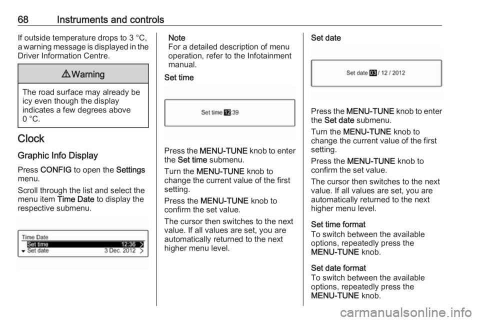
Graphic Info Display Press CONFIG to open the Settings
menu.
Scroll through the list and select the
menu item Time Date to display the
respective submenu.
Note
For a detailed description of menu
operation, refer to the Infotainment
manual.
Set time
Press the MENU-TUNE knob to enter
the Set time submenu.
Turn the MENU-TUNE knob to
change the current value of the first setting.
Press the MENU-TUNE knob to
confirm the set value.
The cursor then switches to the next
value. If all values are set, you are
automatically returned to the next
higher menu level.
Set date
Press the MENU-TUNE knob to enter
the Set date submenu.
Turn the MENU-TUNE knob to
change the current value of the first setting.
Press the MENU-TUNE knob to
confirm the set value.
The cursor then switches to the next
value. If all values are set, you are
automatically returned to the next
higher menu level.
Set time format
To switch between the available
options, repeatedly press the
MENU-TUNE knob.
Set date format
To switch between the available
options, repeatedly press the
MENU-TUNE knob.
Page 73 of 231
Instruments and controls71Warning lights, gauges
and indicators
Instrument cluster
The needles of the instruments briefly
rotate to the end position when the
ignition is switched on.
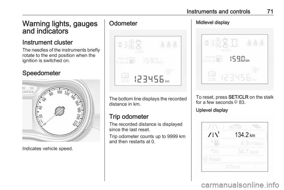
Speedometer
Indicates vehicle speed.
Odometer
The bottom line displays the recorded distance in km.
Trip odometer The recorded distance is displayedsince the last reset.
Trip odometer counts up to 9999 km
and then restarts at 0.
Midlevel display
To reset, press SET/CLR on the stalk
for a few seconds 3 83.
Uplevel display
Page 74 of 231
72Instruments and controlsTwo trip odometer pages are
selectable for different trips.
Select menu ; by pressing Menu
on the stalk. Turn adjuster wheel on
the stalk and select ;1 or ; 2.
Each trip odometer page can be reset
separately by pressing SET/CLR on
the stalk for a few seconds on the
respective menu.
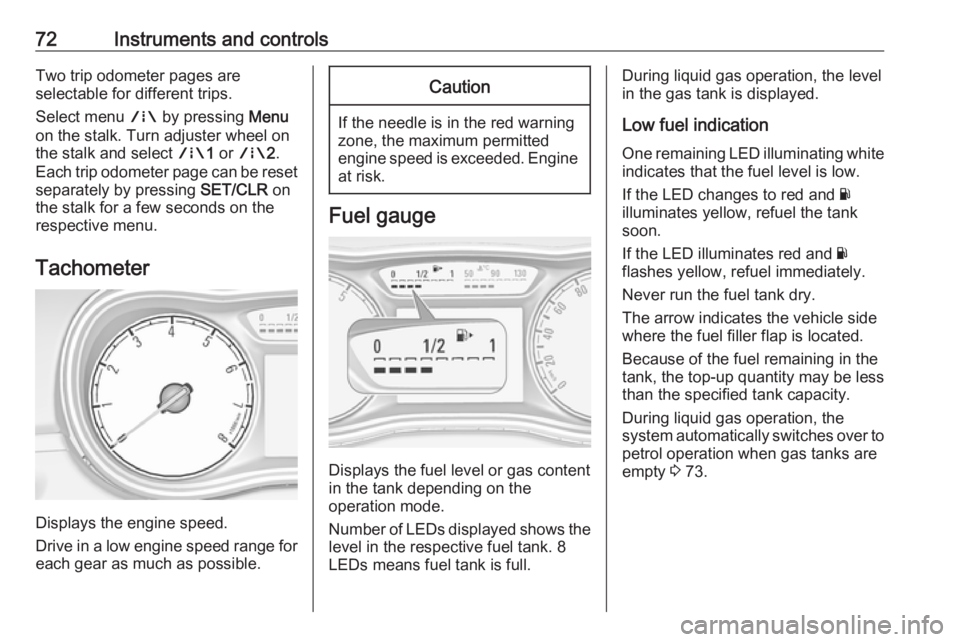
Tachometer
Displays the engine speed.
Drive in a low engine speed range for each gear as much as possible.
Caution
If the needle is in the red warning
zone, the maximum permitted
engine speed is exceeded. Engine at risk.
Fuel gauge
Displays the fuel level or gas content
in the tank depending on the
operation mode.
Number of LEDs displayed shows the level in the respective fuel tank. 8
LEDs means fuel tank is full.
During liquid gas operation, the level
in the gas tank is displayed.
Low fuel indication
One remaining LED illuminating white indicates that the fuel level is low.
If the LED changes to red and Y
illuminates yellow, refuel the tank soon.
If the LED illuminates red and Y
flashes yellow, refuel immediately.
Never run the fuel tank dry.
The arrow indicates the vehicle side
where the fuel filler flap is located.
Because of the fuel remaining in the
tank, the top-up quantity may be less
than the specified tank capacity.
During liquid gas operation, the
system automatically switches over to
petrol operation when gas tanks are
empty 3 73.
Page 76 of 231
74Instruments and controlsCaution
Repairs and adjustments may onlybe made by trained specialists in
order to maintain the safety and
warranty on the LPG system.
Liquid gas is given a particular odour
(odorised) so that any leaks can be
detected easily.
9 Warning
If you smell gas in the vehicle or in
the immediate vicinity, switch to petrol mode immediately. No
smoking. No naked flames or
ignition sources.
If the gas odour persists, do not start
the engine. Have the cause of the
fault remedied by a workshop.
When using underground car parks,
follow the instructions of the operator
and local laws.
Note
In the event of an accident, switch off
the ignition.
Fuel for liquid gas operation 3 152.
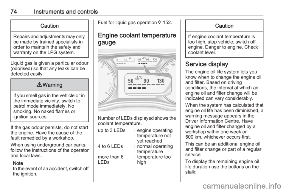
Engine coolant temperature gauge
Number of LEDs displayed shows the coolant temperature.
up to 3 LEDs:engine operating
temperature not
yet reached4 to 6 LEDs:normal operating
temperaturemore than 6
LEDs:temperature too
highCaution
If engine coolant temperature is
too high, stop vehicle, switch off
engine. Danger to engine. Check
coolant level.
Service display
The engine oil life system lets you
know when to change the engine oil
and filter. Based on driving
conditions, the interval at which an
engine oil and filter change will be
indicated can vary considerably.
When the system has calculated that
engine oil life has been diminished, a warning message appears in theDriver Information Centre. Have
engine oil and filter changed by a
workshop within one week or
500 km, whichever occurs first.
This can be an additional engine oil
and filter change or part of a regular
service.
To display the remaining engine oil
life duration use the buttons on the
stalk: