brake sensor OPEL CORSA E 2019 Manual user
[x] Cancel search | Manufacturer: OPEL, Model Year: 2019, Model line: CORSA E, Model: OPEL CORSA E 2019Pages: 231, PDF Size: 6.87 MB
Page 64 of 231
62Storage●Use the hook at the right sidewall
of the load compartment for
hanging up carrier bags.
Maximum load: 5 kg.
● Do not allow the load to protrude above the upper edge of the
backrests.
● Do not place any objects on the load compartment cover or theinstrument panel.
● Do not cover the sensor on top of
the instrument panel.
● The load must not obstruct the operation of the pedals, parking
brake and gear selector lever, or
hinder the freedom of movement of the driver. Do not place any
unsecured objects in the interior.
● Do not drive with an open load compartment.9Warning
Always make sure that the load in
the vehicle is securely stowed.
Otherwise objects can be thrown
around inside the vehicle and
cause personal injury or damage
to the load or vehicle.
● The payload is the difference between the permitted gross
vehicle weight (see identification
plate 3 206) and the EC kerb
weight.
To calculate the payload, enter
the data for your vehicle in the
weights table at the front of this
manual.
The EC kerb weight includes
weights for the driver (68 kg),
luggage (7 kg) and all fluids (fuel
tank 90% full).
Optional equipment and
accessories increase the kerb
weight.
● Driving with a roof load increases
the sensitivity of the vehicle to
cross-winds and has a
detrimental effect on vehicle
handling due to the vehicle's
higher centre of gravity.
Distribute the load evenly and secure it properly with retaining
straps. Adjust the tyre pressure
and vehicle speed according to
the load conditions. Check and
retighten the straps frequently.
Do not drive faster than
120 km/h.
The permissible roof load is
75 kg. The roof load is the
combined weight of the roof rack and the load.
Page 83 of 231
Instruments and controls81or
Fault due to sensors that are dirty or
covered by ice or snow
or
Interference due to external sources of ultrasound. Once the source ofinterference is removed, the system
will operate normally.
Have the cause of the fault in the
system remedied by a workshop.
Parking assist 3 141.
Electronic Stability Control and Traction Control system
b flashes or illuminates yellow.
Flashes
The system is actively engaged.
Engine output may be reduced and
the vehicle may be braked
automatically to a small degree.
Illuminates
A fault in the system is present. A
warning message or warning code
appears in the Driver Information
Centre. Continued driving is possible.The system is not operational. Driving stability, however, may deteriorate
depending on road surface
conditions.
Have the cause of the fault remedied
by a workshop.
Electronic Stability Control 3 133.
Traction Control system 3 133.
Exhaust filter
% illuminates or flashes yellow.
The exhaust filter requires cleaning.
Continue driving until %
extinguishes. If possible, do not allow engine speed to drop below
2000 rpm.
Illuminates
The exhaust filter is full. Start cleaning
process as soon as possible.
Flashes
The maximum filling level of the filter
is reached. Start cleaning process
immediately to avoid damage to the
engine.
Exhaust filter 3 125.Stop-start system 3 122.
Tyre pressure monitoring system
w illuminates or flashes yellow.
Illuminates
Tyre pressure loss. Stop immediately
and check tyre pressure.
Flashes
Fault in system or tyre without
pressure sensor mounted ( e.g. spare
wheel). After 60-90 seconds the
control indicator illuminates
continuously. Consult a workshop.
Tyre pressure monitoring system
3 180.
Engine oil pressure
I illuminates red.
Illuminates when the ignition is
switched on and extinguishes shortly
after the engine starts.
Page 92 of 231
90Instruments and controlsVehicle messages on Midlevel
display
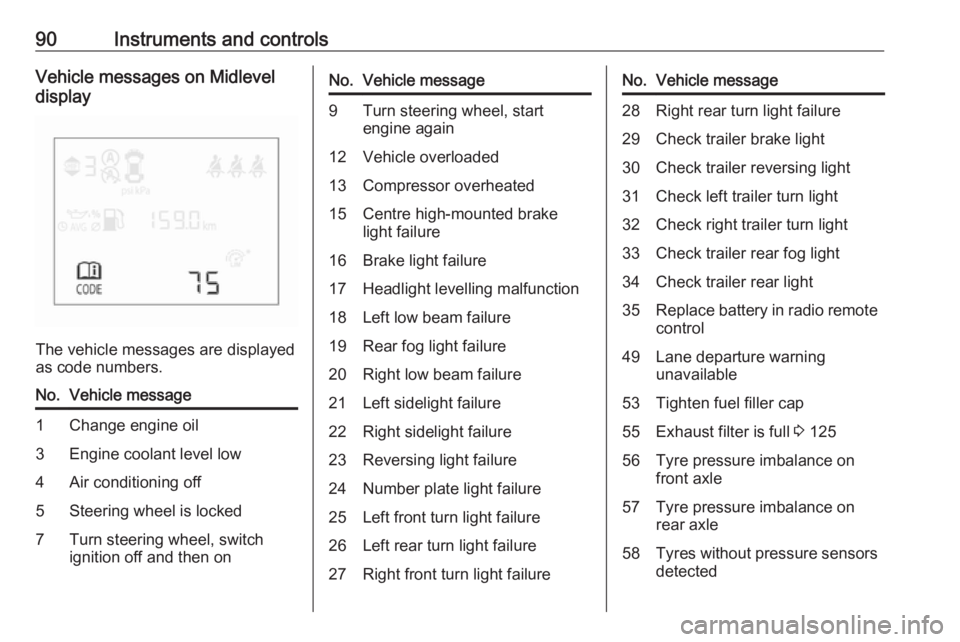
The vehicle messages are displayed
as code numbers.
No.Vehicle message1Change engine oil3Engine coolant level low4Air conditioning off5Steering wheel is locked7Turn steering wheel, switch
ignition off and then onNo.Vehicle message9Turn steering wheel, start
engine again12Vehicle overloaded13Compressor overheated15Centre high-mounted brake
light failure16Brake light failure17Headlight levelling malfunction18Left low beam failure19Rear fog light failure20Right low beam failure21Left sidelight failure22Right sidelight failure23Reversing light failure24Number plate light failure25Left front turn light failure26Left rear turn light failure27Right front turn light failureNo.Vehicle message28Right rear turn light failure29Check trailer brake light30Check trailer reversing light31Check left trailer turn light32Check right trailer turn light33Check trailer rear fog light34Check trailer rear light35Replace battery in radio remote
control49Lane departure warning
unavailable53Tighten fuel filler cap55Exhaust filter is full 3 12556Tyre pressure imbalance on
front axle57Tyre pressure imbalance on
rear axle58Tyres without pressure sensors
detected
Page 142 of 231
140Driving and operatingGeneral information9Warning
Forward collision alert is just a
warning system and does not
apply the brakes. When
approaching a vehicle ahead too
rapidly, it may not provide you
enough time to avoid a collision.
The driver accepts full
responsibility for the appropriate
following distance based on traffic, weather and visibility conditions.
The complete attention of the
driver is always required while
driving. The driver must always be
ready to take action and apply the
brakes.
System limitations
The system is designed to warn of vehicles only, but may react also to
other objects.
In the following cases, forward
collision alert may not detect a vehicle ahead or sensor performance is
limited:
● on winding roads
● when weather limits visibility, e.g.
fog, rain, or snow
● when the sensor is blocked by snow, ice, slush, mud, dirt,
windscreen damage or affected
by foreign items, e.g. stickers
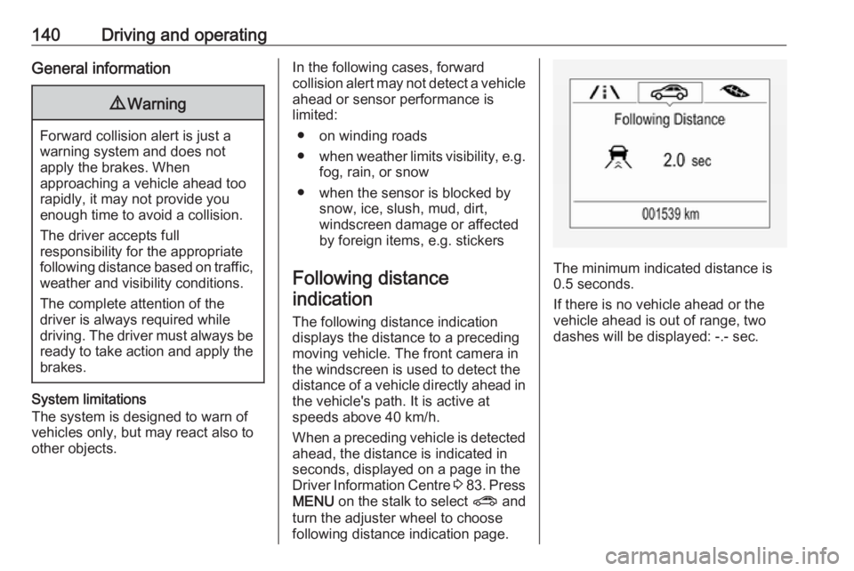
Following distance indication
The following distance indication
displays the distance to a preceding
moving vehicle. The front camera in
the windscreen is used to detect the
distance of a vehicle directly ahead in
the vehicle's path. It is active at
speeds above 40 km/h.
When a preceding vehicle is detected
ahead, the distance is indicated in
seconds, displayed on a page in the
Driver Information Centre 3 83 . Press
MENU on the stalk to select ? and
turn the adjuster wheel to choose following distance indication page.
The minimum indicated distance is 0.5 seconds.
If there is no vehicle ahead or the
vehicle ahead is out of range, two
dashes will be displayed: -.- sec.
Page 176 of 231
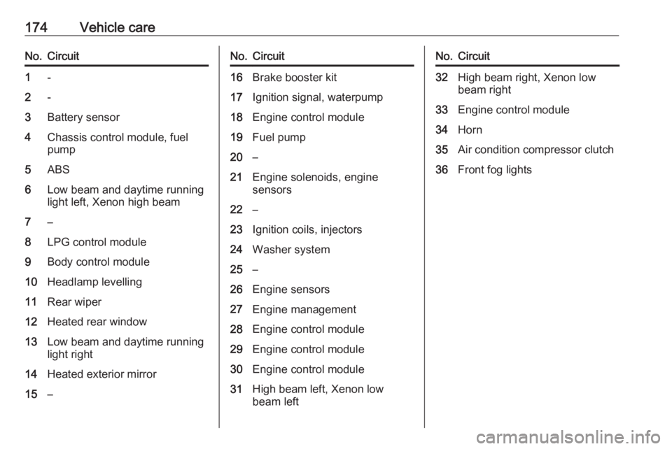
174Vehicle careNo.Circuit1-2-3Battery sensor4Chassis control module, fuel
pump5ABS6Low beam and daytime running
light left, Xenon high beam7–8LPG control module9Body control module10Headlamp levelling11Rear wiper12Heated rear window13Low beam and daytime running
light right14Heated exterior mirror15–No.Circuit16Brake booster kit17Ignition signal, waterpump18Engine control module19Fuel pump20–21Engine solenoids, engine
sensors22–23Ignition coils, injectors24Washer system25–26Engine sensors27Engine management28Engine control module29Engine control module30Engine control module31High beam left, Xenon low
beam leftNo.Circuit32High beam right, Xenon low
beam right33Engine control module34Horn35Air condition compressor clutch36Front fog lights
Page 178 of 231
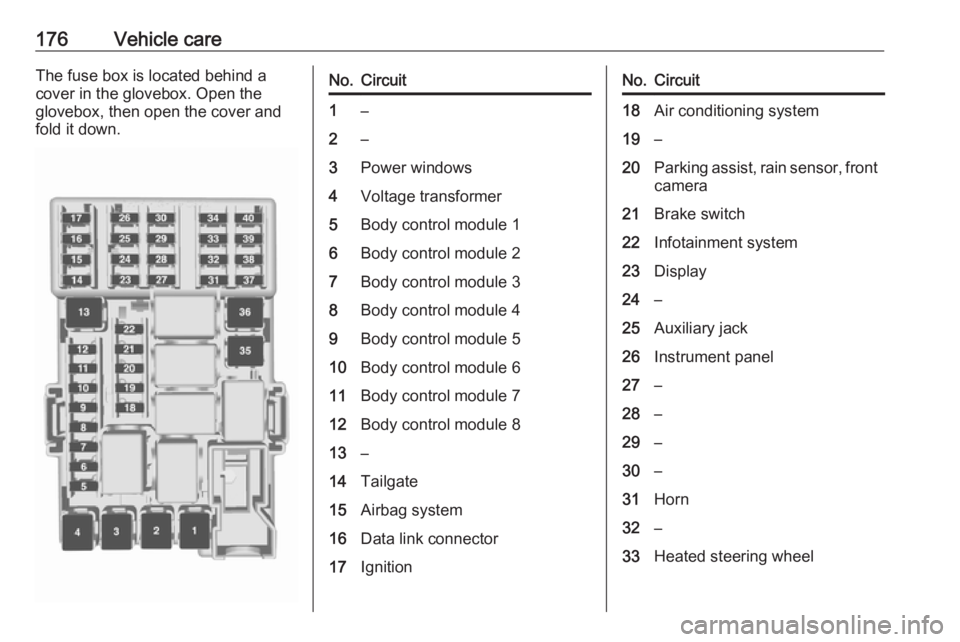
176Vehicle careThe fuse box is located behind a
cover in the glovebox. Open the
glovebox, then open the cover and
fold it down.No.Circuit1–2–3Power windows4Voltage transformer5Body control module 16Body control module 27Body control module 38Body control module 49Body control module 510Body control module 611Body control module 712Body control module 813–14Tailgate15Airbag system16Data link connector17IgnitionNo.Circuit18Air conditioning system19–20Parking assist, rain sensor, front camera21Brake switch22Infotainment system23Display24–25Auxiliary jack26Instrument panel27–28–29–30–31Horn32–33Heated steering wheel
Page 184 of 231
182Vehicle careThe use of commercially-availableliquid tyre repair kits can impair the
function of the system. Factory-
approved repair kits can be used.
Operating electronic devices or being close to facilities using similar wave
frequencies could disrupt the tyre
pressure monitoring system.
Each time the tyres are replaced, tyre
pressure monitoring system sensors
must be dismounted and serviced. For the screwed sensor; replace
valve core and sealing ring. For the
clipped sensor; replace complete
valve stem.
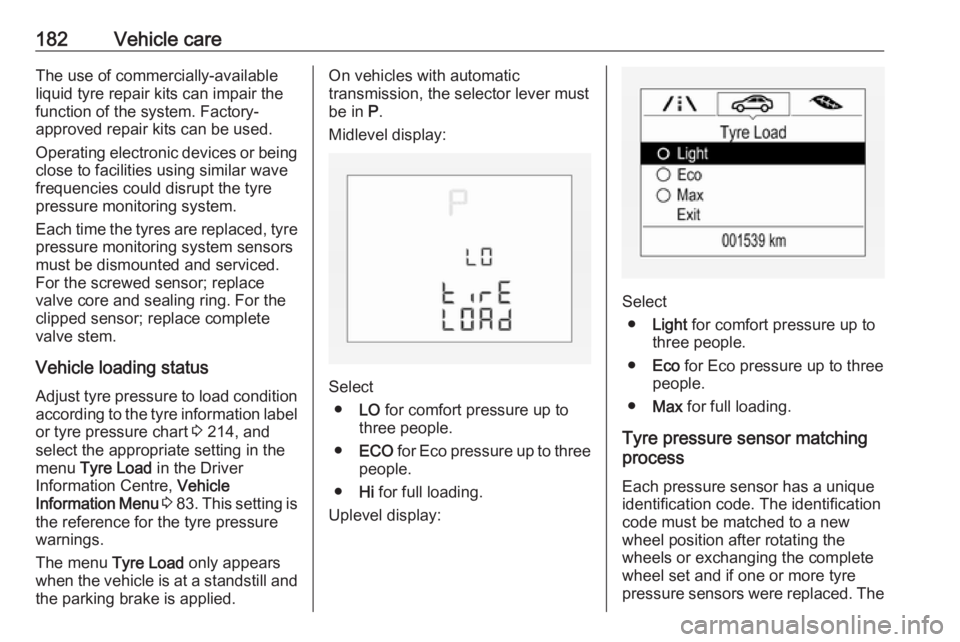
Vehicle loading status
Adjust tyre pressure to load condition according to the tyre information labelor tyre pressure chart 3 214, and
select the appropriate setting in the menu Tyre Load in the Driver
Information Centre, Vehicle
Information Menu 3 83 . This setting is
the reference for the tyre pressure
warnings.
The menu Tyre Load only appears
when the vehicle is at a standstill and
the parking brake is applied.On vehicles with automatic
transmission, the selector lever must
be in P.
Midlevel display:
Select ● LO for comfort pressure up to
three people.
● ECO for Eco pressure up to three
people.
● Hi for full loading.
Uplevel display:
Select ● Light for comfort pressure up to
three people.
● Eco for Eco pressure up to three
people.
● Max for full loading.
Tyre pressure sensor matching
process
Each pressure sensor has a unique identification code. The identification
code must be matched to a new
wheel position after rotating the
wheels or exchanging the complete
wheel set and if one or more tyre
pressure sensors were replaced. The
Page 185 of 231
Vehicle care183tyre pressure sensor matching
process should also be performed
after replacing a spare wheel with a
road wheel containing a tyre pressure
sensor.
The malfunction light w and the
warning message or code should
extinguish at the next ignition cycle. The sensors are matched to the
wheel positions, using a relearn tool,
in the following order: left side front
wheel, right side front wheel, right
side rear wheel and left side rear
wheel. The turn light at the current
active position is illuminated until
sensor is matched.
Consult a workshop for service. There
are 2 minutes to match the first wheel position, and 5 minutes overall to
match all four wheel positions. If it
takes longer, the matching process
stops and must be restarted.
The tyre pressure sensor matching
process is:
1. Apply the parking brake.
2. Turn the ignition on.3. On vehicles with automatic transmission: set the selector
lever to P.
On vehicles with manual
transmission: select neutral.
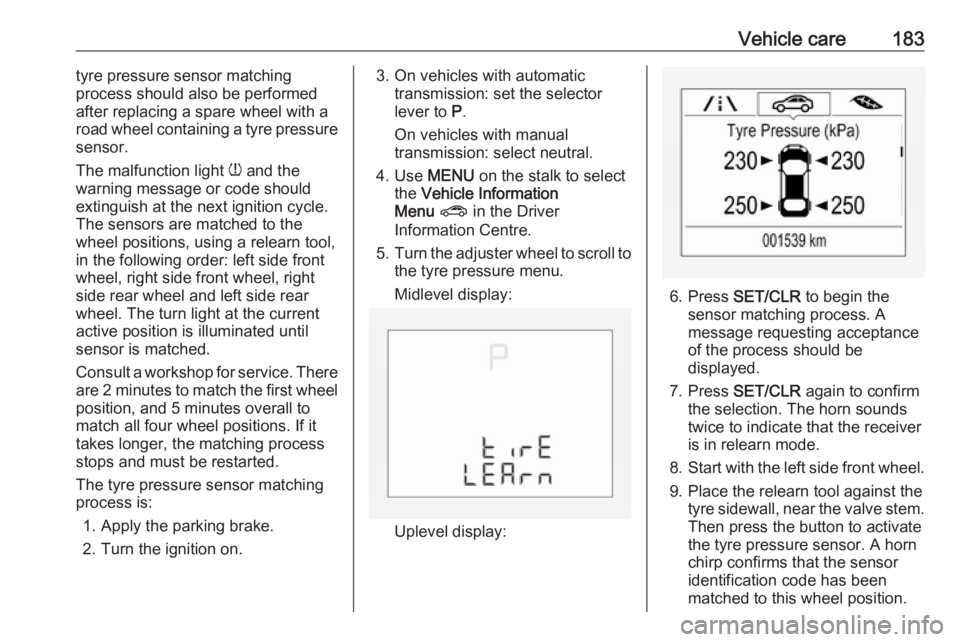
4. Use MENU on the stalk to select
the Vehicle Information
Menu ? in the Driver
Information Centre.
5. Turn the adjuster wheel to scroll to
the tyre pressure menu.
Midlevel display:
Uplevel display:
6. Press SET/CLR to begin the
sensor matching process. A
message requesting acceptance
of the process should be
displayed.
7. Press SET/CLR again to confirm
the selection. The horn sounds
twice to indicate that the receiver
is in relearn mode.
8. Start with the left side front wheel.
9. Place the relearn tool against the tyre sidewall, near the valve stem.Then press the button to activate
the tyre pressure sensor. A horn
chirp confirms that the sensor
identification code has been
matched to this wheel position.
Page 223 of 231
Customer information221Operating data in the vehicleControl units process data for
operation of the vehicle.
This data includes, e.g.: ● vehicle status information (e.g. speed, movement delay, lateral
acceleration, wheel rotation rate,
"seat belts fastened" display)
● ambient conditions (e.g. temperature, rain sensor,
distance sensor)
As a rule such data is transient, not
stored for longer than an operational
cycle, and only processed on board
the vehicle itself. Control units often
include data storage (including the
vehicle key). This is used to allow
information to be documented
temporarily or permanently on vehicle
condition, component stress,
maintenance requirements and
technical events and errors.Depending on technical equipment
levels, the data stored is as follows:
● system component operating states (e.g. fill level, tyre
pressure, battery status)
● faults and defects in important system components (e.g. lights,brakes)
● system reactions in special driving situations (e.g. triggering
of an airbag, actuation of the
stability control systems)
● information on events damaging the vehicle
● for electric vehicles the amount of
charge in the high-voltage
battery, estimated range
In special cases (e.g. if the vehicle
has detected a malfunction), it may be
necessary to save data that would
otherwise just be volatile.
When you use services (e.g. repairs,
maintenance), the operating data
saved can be read together with the
vehicle identification number and
used where necessary. Staff working
for the service network ( e.g. garages,
manufacturers) or third parties (e.g.breakdown services) can read the
data from the vehicle. The same
applies to warranty work and quality
assurance measures.
Data is generally read via the OBD
(On-Board Diagnostics) port
prescribed by law in the vehicle. The operating datawhich is read out,
documents the technical condition of
the vehicle or individual components
and assists with fault diagnosis,
compliance with warranty obligations
and quality improvement. This data,
in particular information on
component stress, technical events,
operator errors and other faults, is
transmitted to the manufacturer
where appropriate, together with the
vehicle identification number. The
manufacturer is also subject to
product liability. The manufacturer
potentially also uses operating data
from vehicles for product recalls. This
data can also be used to check
customer warranty and guarantee
claims.
Fault memories in the vehicle can be
reset by a service company when
carrying out servicing or repairs or at
your request.