brake light OPEL CORSA F 2020 Manual user
[x] Cancel search | Manufacturer: OPEL, Model Year: 2020, Model line: CORSA F, Model: OPEL CORSA F 2020Pages: 229, PDF Size: 21.14 MB
Page 133 of 229

Driving and operating131take action and depress the brake
pedal if you need to brake more
quickly.
Hill considerations9 Warning
Do not use the adaptive cruise
control on steep hill roads.
System performance on hills depends
on vehicle speed, vehicle load, traffic
conditions and the road gradient. It
may not detect a vehicle in your path
while driving on hills. On steep hills,
you may have to use the accelerator
pedal to maintain your vehicle speed.
When going downhill you may have to brake to maintain or reduce your
speed.
Note that applying the brake
deactivates the system.
Radar unit
The radar unit is located in the middle of the front bumper.
9 Warning
The radar unit was aligned
carefully during manufacture.
Therefore, in the event of a front-
end impact, do not use the system. The front bumper may appear to
be intact, however the sensor
behind may be affected and react
incorrectly. After an accident,
consult a workshop to verify and
adjust the radar unit position.
9 Warning
The usage of a license plate
support may have an impact on
the proper operation of the radar
unit and may limit sensor
perfomance. Vehicles driving
ahead, pedestrians or other
objects located in front of the
vehicle may not be detected by the
system.
Do not use a license plate support on the front bumper to ensure
proper system functionality.
Fault
In the event of a fault with the adaptive cruise control, you are alerted by the
illumination of a warning light and the
display of a message in the
instrument panel, accompanied by an audible signal.
The adaptive cruise control may not
operate correctly if traffic signs do not
comply with the Vienna Convention
on Road Signs and Signals.
Have the system checked by a dealer or a qualified workshop.
Page 134 of 229
132Driving and operatingAs a safety measure, do not use the
system if the brake lights are faulty.
Do not use the system if the front
bumper is damaged.
Active emergency braking
Active emergency braking can help to reduce the damage and injury from
crashes with vehicles and
pedestrians directly ahead, when the
driver does not actively take action
either by manual braking or by
steering. Before the active
emergency braking applies, the driver
is warned by the forward collision
alert.
Forward collision alert 3 135
Front pedestrian protection 3 137
Active emergency braking can be
deactivated in the vehicle
personalisation 3 77. If deactivated,
m illuminates in the instrument
cluster and a warning message is
displayed in the Driver Information
Centre. When ignition is switched on next time, system is activated.The feature uses various inputs (e.g.
camera sensor, radar sensor, brake
pressure, vehicle speed) to calculate
the probability of a frontal collision.9 Warning
This system is not intended to
replace the driver responsibility for driving the vehicle and looking
ahead. Its function is limited to
supplemental use only to reduce
the vehicle speed before a
collision.
The system may not react to
animals. After a sudden lane
change, the system needs a
certain time to detect the next
preceding vehicle.
The driver must always be ready
to take action and apply the brakes and steer to avoid collisions.
9 Warning
The usage of a license plate
support may have an impact on
the proper operation of the radar
unit and may limit sensor
perfomance. Vehicles or
pedestrians driving or walking
ahead may not be detected by the
system.
Do not use a a license plate
support to ensure proper system
functionality.
Functionality
Depending on the vehicle
configuration and the detected
objects, there are several operational speed ranges.
On vehicles equipped only with front
camera, the active emergency
braking operates from 5 km/h to 80 km/h when a vehicle has been
detected.
On vehicles equipped with radar
sensor and front camera, the active
emergency braking operates from
5 km/h to 140 km/h when a vehicle
has been detected.
Active emergency braking only works when the seat belts of the front
passengers are fastened.
Page 135 of 229
Driving and operating133The system includes:● brake preparation system
● emergency automatic braking
● smart brake assist
● forward collision alert
● front pedestrian protection
Brake preparation system
When approaching a vehicle ahead
or a pedestrian so quickly that a
collision is likely, the brake
preparation system slightly
pressurises the brakes. This reduces
the response time, when braking is
requested.
Emergency automatic braking
After activation of brake preparation
system and just before the imminent
collision, this function automatically
applies limited braking to reduce the
impact speed of the collision or
prohibit a crash.
If active emergency braking is
applied, m flashes in the instrument
cluster.Emergency automatic braking can
only occur if a vehicle or a pedestrian ahead is detected.
Forward collision alert 3 135
Front pedestrian protection 3 137
Below a speed of 30 km/h,
emergency automatic braking may
slow down the vehicle to a complete
stop. If the speed exceeds 30 km/h,
emergency automatic braking
reduces the speed. However, the
driver must apply the brake.
Emergency automatic braking may slow the vehicle to a complete stop to
try to avoid a potential crash.
● Automatic transmission: If the vehicle comes to a complete
stop, automatic braking is
maintained for up to two
seconds. Keep the brake pedal
depressed to prevent the vehicle
from starting off again.
● Manual transmission: If the vehicle comes to a complete
stop, the engine may stall.
Operation of the function may be felt
by a slight vibration in the brake
pedal.9 Warning
Emergency automatic braking is
an emergency crash preparation
feature and is not designed to
avoid crashes. Do not rely on the
system to brake the vehicle.
Emergency automatic braking will
not brake outside of its operating speed range and only responds to
detected vehicles and
pedestrians.
Smart brake assist
Smart brake assist provides a boost
to braking when the brake pedal is quickly applied. The braking is based on the speed of approach and
distance to a vehicle ahead.
Minor brake pedal pulsations or pedal
movement during this time is normal
and the brake pedal should continue to be applied as needed. Intelligent
brake assist will automatically
disengage only when the brake pedal is released.
Page 136 of 229
134Driving and operating9Warning
Smart brake assist may increase
vehicle braking in situations when
it may not be necessary. You
could block the flow of traffic. If this occurs, take your foot off the brakepedal and then apply the brakes
as needed.
Forward collision alert 3 135.
Front pedestrian protection 3 137.
System limitations In some cases, the active emergencybraking system may provide an
automatic braking in situations that
seem to be unnecessary, for instance
in parking garages, due to various
types of objects, i.e., traffic signs or
vehicles in another lane. This is
normal operation, the vehicle does
not need service. Firmly apply the
accelerator pedal to override the
automatic braking if the situation and
the surroundings permit.
In the following cases, active
emergency braking performance
might be limited:
● driving on winding or hilly roads
● detecting vehicles with a trailer, tractors, muddy vehicles, etc.
● detecting a vehicle when weather
limits visibility, such as in fog,
rain, or snow
● driving during nighttime
● the sensor in the windscreen or the radar unit behind the front
bumper are blocked by snow, ice,
slush, mud, dirt etc.
● the windscreen is damaged or affected by foreign objects, e.g.
stickers
the bumper is damaged or
affected by foreign objects, e.g.
license plate support
Complete attention is always required
while driving, and you should be
ready to take action and apply the
brakes and / or steer the vehicle to
avoid crashes.We recommend to deactivate the
system in the vehicle personalisation
in the following cases:
● when towing a trailer or caravan
● when carrying long objects on roof bars or a roof rack
● when the vehicle is being towed with the engine running
● when the vehicle is fitted with snow chains
● when a spare wheel is fitted that is smaller than the other wheels
● before using an automatic car wash with the engine running
● before placing the vehicle on a rolling road in a workshop
● if the windscreen has been damaged close to the camera
● if the front bumper has been damaged
● if the brake lights are not working
Fault
In case the system requires a service,
a message is displayed in the Driver
Information Centre.
Page 154 of 229

152Driving and operating
The system recognises the traffic
signs above and displays them in the
Driver Information Centre.
9 Warning
The actual traffic sign always
takes priority over the traffic sign displayed in the Driver Information Centre.
If the vehicle enters a road of whichthe entry is prohibited, the no entry
traffic symbol and a warning message are displayed in the Driver
Information Centre. If the system
detects one of the other traffic signs,
the respective traffic sign is displayed
in the Driver Information Centre.
Speed limiter 3 122
Cruise control 3 120
Adaptive cruise control 3 124
Lane keep assist
Lane keep assist supports the driver
to avoid unintended leaving of the
lane. The front camera observes road
edges, as well as the lane markings
between which the vehicle is driving.
If the vehicle approaches a road edge or a lane marking, the steering wheel
is gently turned to position so that the
vehicle turns back into the lane. The
driver will then notice a turning
movement of the steering wheel. Turn steering wheel in same direction, if
the system does not steer sufficiently.
Turn steering wheel gently into
opposite direction, if lane change is
intended.
When the system steers to correct the trajectory of the vehicle, L flashes
yellow in the instrument cluster.
Unintended lane departure is not
assumed by the system when the turn lights are operated and during few
seconds after turn lights have been
switched off.Note
The system may be switched off if it
detects lanes which are too narrow,
too wide or too curved.
Following preconditions have to be
fulfilled:
● vehicle speed must be between 65 km/h and 180 km/h
● the driver must hold the steering wheel
● the turn lights are not activated
● the electronic stability control is activated and not in operation
● the vehicle is not connected to a trailer or an electric bicycle carrier
● normal driving behaviour (system
detects dynamic driving style, i.e. pressure on the brake or
accelerator pedal)
● roads with good lane markings ● no spare wheel is used
● the driver is not taking the hands off the steering wheel for a longer
time period
● the vehicle is not driven in a tight
corner
Page 160 of 229
158Driving and operatingPetrol and diesel refuelling
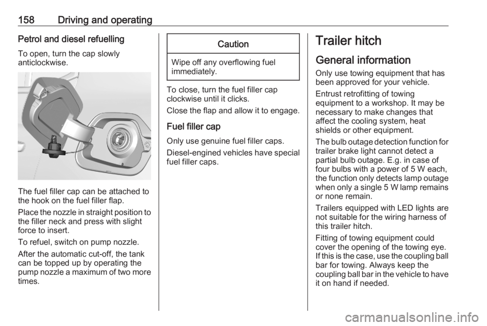
To open, turn the cap slowly
anticlockwise.
The fuel filler cap can be attached to
the hook on the fuel filler flap.
Place the nozzle in straight position to the filler neck and press with slight
force to insert.
To refuel, switch on pump nozzle.
After the automatic cut-off, the tank can be topped up by operating the
pump nozzle a maximum of two more
times.
Caution
Wipe off any overflowing fuel
immediately.
To close, turn the fuel filler cap
clockwise until it clicks.
Close the flap and allow it to engage.
Fuel filler cap
Only use genuine fuel filler caps.
Diesel-engined vehicles have special fuel filler caps.
Trailer hitch
General information
Only use towing equipment that has
been approved for your vehicle.
Entrust retrofitting of towing
equipment to a workshop. It may be
necessary to make changes that
affect the cooling system, heat
shields or other equipment.
The bulb outage detection function for
trailer brake light cannot detect a
partial bulb outage. E.g. in case of
four bulbs with a power of 5 W each,
the function only detects lamp outage when only a single 5 W lamp remains
or none remain.
Trailers equipped with LED lights are
not suitable for the wiring harness of
this trailer hitch.
Fitting of towing equipment could
cover the opening of the towing eye.
If this is the case, use the coupling ball
bar for towing. Always keep the
coupling ball bar in the vehicle to have it on hand if needed.
Page 161 of 229

Driving and operating159Driving characteristics and
towing tips
Before attaching a trailer, lubricate
the coupling ball. However, do not do
so if a stabiliser, which acts on the
coupling ball, is being used to reduce snaking movements.
During trailer towing do not exceed a
speed of 80 km/h. A maximum speed
of 100 km/h is only appropriate if an
oscillation damper is used and the
permissible gross trailer weight does
not exceed the vehicle’s curb weight.
For trailers with low driving stability
and caravan trailers, the use of an
oscillation damper is strongly
recommended.
If the trailer starts snaking, drive more slowly, do not attempt to correct the
steering and brake sharply if
necessary.
When driving downhill, drive in the
same gear as if driving uphill and
drive at a similar speed.
Adjust tyre pressure to the value
specified for full load 3 210.Trailer towing
Trailer loads The permissible trailer loads are
vehicle and engine-dependent
maximum values which must not be
exceeded. The actual trailer load is the difference between the actual
gross weight of the trailer and the
actual coupling socket load with the
trailer coupled.
The permissible trailer loads are
specified in the vehicle documents. In general, they are valid for gradients
up to 12%.
The permissible trailer load applies
up to the specified incline and at sea
level. Since engine power decreases
as altitude increases due to the air
becoming thinner, therefore reducing
climbing ability, the permissible gross
train weight also decreases by 10%
for every 1000 m of altitude. The
gross train weight does not have to be reduced when driving on roads with
slight inclines (less than 8%, e.g.
motorways).The permissible gross train weight
must not be exceeded. This weight is
specified on the identification plate
3 203.
Vertical coupling load
The vertical coupling load is the load
exerted by the trailer on the coupling
ball. It can be varied by changing the
weight distribution when loading the
trailer.
The maximum permissible vertical
coupling load (55 kg) is specified on
the towing equipment identification
plate and in the vehicle documents.
Always aim for the maximum vertical
coupling load, especially in the case
of heavy trailers. The vertical coupling load should never fall below 25 kg.
Page 163 of 229
Vehicle care161Vehicle careGeneral Information...................161
Accessories and vehicle modifications .......................... 161
Vehicle storage ........................162
End-of-life vehicle recovery .....162
Vehicle checks ........................... 163
Performing work ......................163
Bonnet ..................................... 163
Engine oil ................................. 164
Engine coolant ......................... 165
Washer fluid ............................ 165
Brakes ..................................... 166
Brake fluid ............................... 166
Vehicle battery ......................... 166
Diesel fuel system bleeding .....168
Wiper blade replacement ........168
Bulb replacement .......................169
Halogen headlights ..................169
LED headlights ........................ 171
Front fog lights ......................... 171
Front turn lights .......................171
Tail lights ................................. 172
Number plate light ...................174
Interior lights ............................ 174Electrical system........................174
Fuses ....................................... 174
Engine compartment fuse box . 175
Instrument panel fuse box .......176
Vehicle tools .............................. 178
Tools ........................................ 178
Wheels and tyres .......................179
Winter tyres ............................. 179
Tyre designations ....................179
Tyre pressure .......................... 179
Tyre deflation detection system .................................... 180
Tread depth ............................. 181
Changing tyre and wheel size . 182
Wheel covers ........................... 182
Tyre chains .............................. 182
Tyre repair kit .......................... 183
Wheel changing .......................186
Spare wheel ............................ 187
Jump starting ............................. 191
Towing ....................................... 192
Towing the vehicle ...................192
Towing another vehicle ...........193
Appearance care .......................194
Exterior care ............................ 194
Interior care ............................. 196
Floor mats ............................... 196General Information
Accessories and vehicle modifications
We recommend the use of genuine parts and accessories and factory
approved parts specific for your
vehicle type. We cannot assess or
guarantee reliability of other products - even if they have a regulatory or
otherwise granted approval.
Any modification, conversion or other
changes made to standard vehicle
specifications (including, without
limitation, software modifications,
modifications of the electronic control units) may invalidate the warranty
offered by Opel. Furthermore, such
changes may affect driver assistance
systems, may impact fuel
consumption, CO 2 emissions and
other emissions of the vehicle and
cause the vehicle to no longer
conform to the operating permit,
impacting the validity of your vehicle
registration.
Page 175 of 229
Vehicle care173
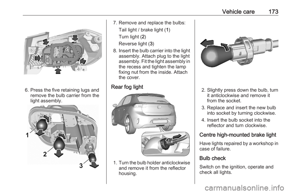
6. Press the five retaining lugs andremove the bulb carrier from the
light assembly.
7. Remove and replace the bulbs:
Tail light / brake light ( 1)
Turn light ( 2)
Reverse light ( 3)
8. Insert the bulb carrier into the light
assembly. Attach plug to the light
assembly. Fit the light assembly in the recess and tighten the lamp
fixing nut from the inside. Attach
the cover.
Rear fog light
1. Turn the bulb holder anticlockwise
and remove it from the reflector
housing.
2. Slightly press down the bulb, turn it anticlockwise and remove it
from the socket.
3. Replace and insert the new bulb into socket by turning clockwise.
4. Insert the bulb socket into the reflector and turn clockwise.
Centre high-mounted brake light Have lights repaired by a workshop in
case of failure.
Bulb check Switch on the ignition, operate and
check all lights.
Page 177 of 229
Vehicle care175Engine compartment fusebox
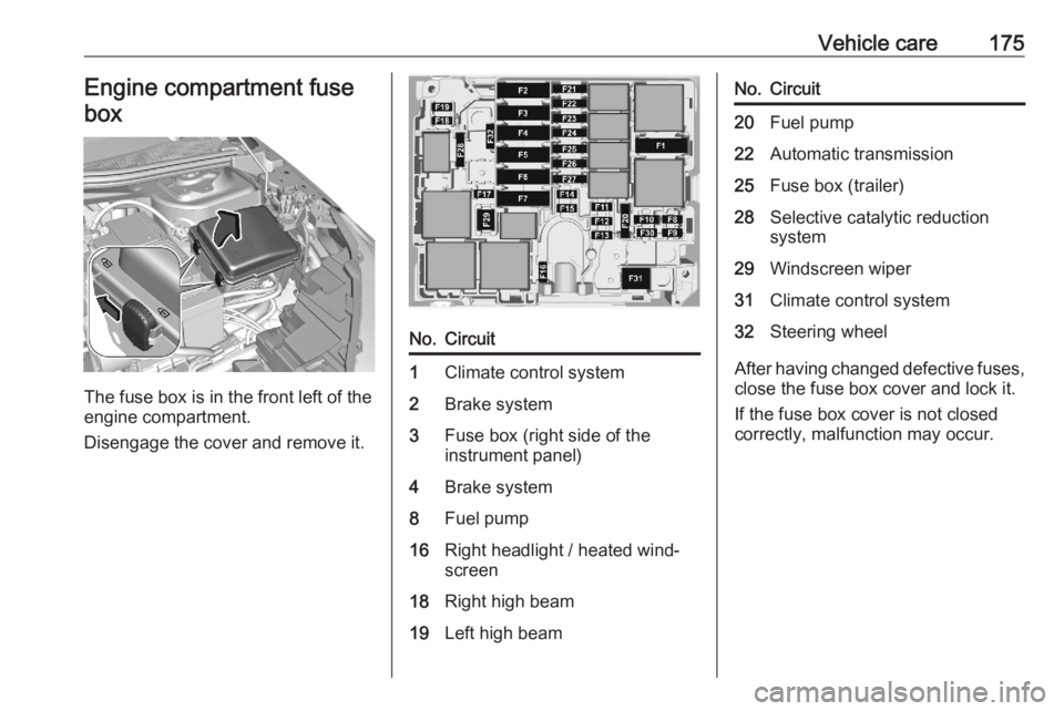
The fuse box is in the front left of the
engine compartment.
Disengage the cover and remove it.
No.Circuit1Climate control system2Brake system3Fuse box (right side of the
instrument panel)4Brake system8Fuel pump16Right headlight / heated wind‐
screen18Right high beam19Left high beamNo.Circuit20Fuel pump22Automatic transmission25Fuse box (trailer)28Selective catalytic reduction
system29Windscreen wiper31Climate control system32Steering wheel
After having changed defective fuses,
close the fuse box cover and lock it.
If the fuse box cover is not closed
correctly, malfunction may occur.