display OPEL CORSA F 2020 Manual user
[x] Cancel search | Manufacturer: OPEL, Model Year: 2020, Model line: CORSA F, Model: OPEL CORSA F 2020Pages: 229, PDF Size: 21.14 MB
Page 151 of 229
Driving and operating149Standard view
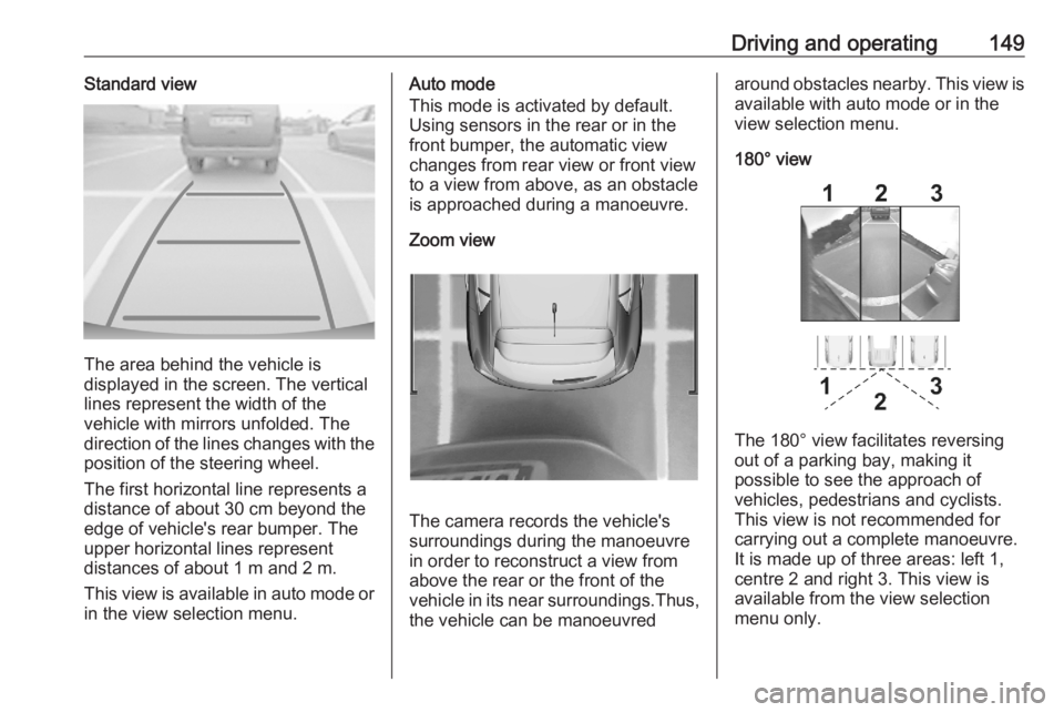
The area behind the vehicle is
displayed in the screen. The vertical
lines represent the width of the
vehicle with mirrors unfolded. The
direction of the lines changes with the position of the steering wheel.
The first horizontal line represents a
distance of about 30 cm beyond the
edge of vehicle's rear bumper. The
upper horizontal lines represent
distances of about 1 m and 2 m.
This view is available in auto mode or
in the view selection menu.
Auto mode
This mode is activated by default.
Using sensors in the rear or in the
front bumper, the automatic view
changes from rear view or front view
to a view from above, as an obstacle is approached during a manoeuvre.
Zoom view
The camera records the vehicle's
surroundings during the manoeuvre
in order to reconstruct a view fromabove the rear or the front of the
vehicle in its near surroundings.Thus,
the vehicle can be manoeuvred
around obstacles nearby. This view is available with auto mode or in the
view selection menu.
180° view
The 180° view facilitates reversing
out of a parking bay, making it
possible to see the approach of
vehicles, pedestrians and cyclists.
This view is not recommended for
carrying out a complete manoeuvre.
It is made up of three areas: left 1,
centre 2 and right 3. This view is
available from the view selection menu only.
Page 152 of 229
150Driving and operatingDeactivation
Panoramic view system is
deactivated when:
● towing an electrically connected trailer, bicycle carrier, etc.
● a certain forward speed is exceeded or if reverse gear is not
engaged for 7 seconds
● by pressing the icon q in the left
upper corner of the touch screen
General information9 Warning
The panoramic view system does
not replace driver vision. It will not display children, pedestrians,
cyclists, crossing traffic, animals,
or any other objects outside of the camera view area, e. g. below the
bumper, or underneath the
vehicle.
Do not drive or park the vehicle
using only the panoramic view
system.
Always check the surrounding of
the vehicle before driving.
Displayed images may be further
or closer than they appear. The
area displayed is limited and
objects that are close to either
edge of the bumper or under the
bumper are not displayed on the
screen.
System limitations
Caution
For optimal operation of the
system, it is important to keep the
lense of the camera in the tailgate between the number plate lightsand the lense in the front grill
below the emblem always clean.
Rinse the lenses with water and
wipe with a soft cloth.
Do not clean the lenses with a
steam-jet or high-pressure jet
cleaner.
The panoramic view system may not
operate properly when:
● The surrounding is dark.
● The sun or the beam of headlights is shining directly into
the camera lenses.
● Weather limits visibility, such as fog, rain, or snow.
● The camera lenses are blocked by snow, ice, slush, mud, dirt.
● The vehicle had an accident. ● There are extreme temperature changes.
Rear view camera The rear view camera assists the
driver when reversing by displaying a
view of the area behind the vehicle.
The view of the camera is displayed
in the Info Display.9 Warning
The rear view camera does not
replace driver vision. Note that
objects that are outside the
Page 153 of 229
Driving and operating151camera's field of view and the
parking assist sensors, e.g. below
the bumper or underneath the
vehicle, are not displayed.
Do not reverse or park the vehicle using only the rear view camera.
Always check the surrounding of
the vehicle before driving.
Switching on
Rear view camera is automatically
activated when reverse gear is
engaged.
Functionality
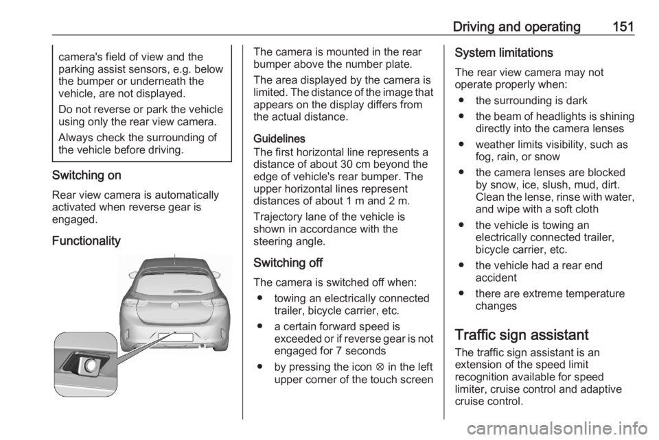
The camera is mounted in the rear
bumper above the number plate.
The area displayed by the camera is
limited. The distance of the image that
appears on the display differs from
the actual distance.
Guidelines
The first horizontal line represents a
distance of about 30 cm beyond the
edge of vehicle's rear bumper. The
upper horizontal lines represent
distances of about 1 m and 2 m.
Trajectory lane of the vehicle is
shown in accordance with the
steering angle.
Switching off
The camera is switched off when: ● towing an electrically connected trailer, bicycle carrier, etc.
● a certain forward speed is exceeded or if reverse gear is not
engaged for 7 seconds
● by pressing the icon q in the left
upper corner of the touch screenSystem limitations
The rear view camera may not
operate properly when:
● the surrounding is dark
● the beam of headlights is shining
directly into the camera lenses
● weather limits visibility, such as fog, rain, or snow
● the camera lenses are blocked by snow, ice, slush, mud, dirt.Clean the lense, rinse with water,
and wipe with a soft cloth
● the vehicle is towing an electrically connected trailer,
bicycle carrier, etc.
● the vehicle had a rear end accident
● there are extreme temperature changes
Traffic sign assistant
The traffic sign assistant is an
extension of the speed limit
recognition available for speed
limiter, cruise control and adaptive
cruise control.
Page 154 of 229

152Driving and operating
The system recognises the traffic
signs above and displays them in the
Driver Information Centre.
9 Warning
The actual traffic sign always
takes priority over the traffic sign displayed in the Driver Information Centre.
If the vehicle enters a road of whichthe entry is prohibited, the no entry
traffic symbol and a warning message are displayed in the Driver
Information Centre. If the system
detects one of the other traffic signs,
the respective traffic sign is displayed
in the Driver Information Centre.
Speed limiter 3 122
Cruise control 3 120
Adaptive cruise control 3 124
Lane keep assist
Lane keep assist supports the driver
to avoid unintended leaving of the
lane. The front camera observes road
edges, as well as the lane markings
between which the vehicle is driving.
If the vehicle approaches a road edge or a lane marking, the steering wheel
is gently turned to position so that the
vehicle turns back into the lane. The
driver will then notice a turning
movement of the steering wheel. Turn steering wheel in same direction, if
the system does not steer sufficiently.
Turn steering wheel gently into
opposite direction, if lane change is
intended.
When the system steers to correct the trajectory of the vehicle, L flashes
yellow in the instrument cluster.
Unintended lane departure is not
assumed by the system when the turn lights are operated and during few
seconds after turn lights have been
switched off.Note
The system may be switched off if it
detects lanes which are too narrow,
too wide or too curved.
Following preconditions have to be
fulfilled:
● vehicle speed must be between 65 km/h and 180 km/h
● the driver must hold the steering wheel
● the turn lights are not activated
● the electronic stability control is activated and not in operation
● the vehicle is not connected to a trailer or an electric bicycle carrier
● normal driving behaviour (system
detects dynamic driving style, i.e. pressure on the brake or
accelerator pedal)
● roads with good lane markings ● no spare wheel is used
● the driver is not taking the hands off the steering wheel for a longer
time period
● the vehicle is not driven in a tight
corner
Page 155 of 229

Driving and operating153Activation
If the system is activated, the LED in
the button j is not illuminated. To
activate the system when the system
is deactivated, press j.
The system is operational at vehicle
speeds between 65 km/h and
180 km/h and if lane markings are
detectable. The driver must hold the
steering wheel. The electronic
stability control system must be
activated.
The control indicator L flashes
yellow during trajectory correction.
If the driver wishes to maintain the
trajectory of the vehicle, he can
interrupt the correction by keeping a
firm grip on the steering wheel, e.g.
during an avoiding manoeuvre. The
correction is interrupted if the turn
lights are operated. If the vehicle is
equipped with active side blind spot detection, the interruption of the lane
correction might be cancelled.
Side blind zone assistant 3 146.
There is no correction triggered when
the turn lights are operated and
during few seconds after turn lights
have been switched off.
If the system detects that the driver is not holding the steering wheel
permanently, it interrupts the
correction. A warning message in the
Driver Information Centre
accompanied by a warning chime
alerts the driver when immediate
driver´s action is required.Deactivation
To deactivate the system, press and
hold j. Deactivation of the system is
confirmed by the illuminated LED in
the button and L illuminates yellow
in the instrument cluster.
Fault
In the event of a fault, L and C
appear in the instrument panel,
accompanied by a display message
and a warning chime. Contact a
dealer or a qualified workshop to have the system checked.
System limitations The system performance may be
affected by:
● a dirty or foggy windscreen or if the windscreen is affected by
foreign objects, e.g. stickers
● close vehicles ahead
● banked roads
● winding or hilly roads
● road edges
● sudden lighting changes
Page 182 of 229

180Vehicle careThe tyre pressure information labelon the right door frame indicates theoriginal equipment tyres and the
correspondent tyre pressures.
The tyre pressure data refers to cold
tyres. It applies to summer and winter tyres.
Always inflate the spare tyre to the
pressure specified for full load.
Incorrect tyre pressures will impair
safety, vehicle handling, comfort and fuel economy and will increase tyre
wear.
Tyre pressures differ depending on
various options. For the correct tyre
pressure value, follow the procedure
below:
1. Identify the engine identifier code.
Engine data 3 207.
2. Identify the respective tyre.
The tyre pressure tables show all
possible tyre combinations 3 210.
For the tyres approved for your
vehicle, refer to the EEC Certificate of
Conformity provided with your vehicle
or other national registration
documents.The driver is responsible for correct
adjustment of tyre pressure.9 Warning
If the pressure is too low, this can
result in considerable tyre warm-
up and internal damage, leading to tread separation and even to tyre
blow-out at high speeds.
9 Warning
For specific tyres the
recommended tyre pressure as
shown in the tyre pressure table may exceed the maximum tyre
pressure as indicated on the tyre.
Never exceed the maximum tyre
pressure as indicated on the tyre.
Temperature dependency
The tyre pressure depends on the
temperature of the tyre. During
driving, tyre temperature and
pressure increase. Tyre pressure
values provided on the tyre
information label and tyre pressure
chart are valid for cold tyres, which means at 20 °C.
The pressure increases by nearly
10 kPa for a 10 °C temperature
increase. This must be considered
when warm tyres are checked.
Tyre deflation detectionsystem
The tyre deflation detection system
continually checks the rotation speed
of all four wheels and warns on low
tyre pressure condition once vehicle
is driving. This is achieved by
comparing tyre rolling circumference
with reference values and further
signals.
If a tyre loses pressure the control
indicator w illuminates and a warning
message is displayed in the Driver Information Centre.
Control indicator w 3 71.
In this case reduce speed, avoid
sharp cornering and strong braking.
Stop at next safe opportunity and
check tyre pressure.
Page 183 of 229
Vehicle care181After adjusting tyre pressure initialise
system to extinguish the control
indicator and restart system.
If the failure continues to be
displayed, contact a workshop. The
system is inoperable when ABS or
ESC has a malfunction or a
temporary spare wheel is used. Once
the tyre has been refitted, check the
tyre pressure with cold tyres and
initialise the system.Caution
Deflation detection system warns
just about low tyre pressure
condition and does not replace
regular tyre maintenance by the
driver.
System initialisation
After tyre pressure correction or
wheel change, the system must be
initialised to learn new circumference
reference values:
1. Always ensure that all four tyres have correct tyre pressure3 210.
2. Apply parking brake. 3. Initialise the system via the Info Display 3 75.
4. Reset is confirmed by pop-up indication.
After initialisation system
automatically calibrates to new tyre
pressures during driving. After longer
drive the system will adopt and
monitor new pressures.
Always check tyre pressure with cold
tyres.
System has to be reinitialised when: ● Tyre pressure has been changed
● Load condition has been changed
● Wheels have been swapped or exchanged
The system will not warn
instantaneously on a tyre blow out or
a rapid deflation. This is due to
required calculation time.Tread depth
Check tread depth at regular
intervals.
Tyres should be replaced for safety
reasons at a tread depth of 2-3 mm
(4 mm for winter tyres).
For safety reasons, it is
recommended that the tread depth of
the tyres on one axle should not vary
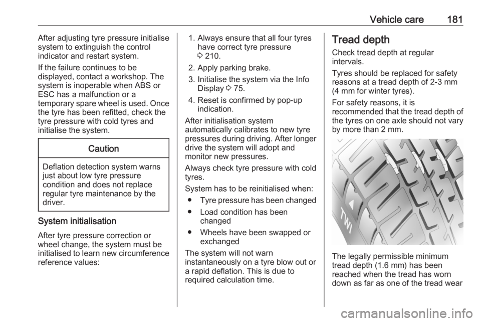
by more than 2 mm.
The legally permissible minimum
tread depth (1.6 mm) has been
reached when the tread has worn
down as far as one of the tread wear
Page 198 of 229
196Vehicle careInterior careInterior and upholstery
Only clean the vehicle interior,
including the instrument panel fascia
and panelling, with a dry cloth or
interior cleaner.
Clean the leather upholstery with
clear water and a soft cloth. In case of
heavy soiling, use leather care.
The instrument cluster and the
displays should only be cleaned using a soft damp cloth. If necessary use aweak soap solution.
Clean fabric upholstery with a
vacuum cleaner and brush. Remove
stains with an upholstery cleaner.
Clothing fabrics may not be
colourfast. This could cause visible
discolourations, especially on light-
coloured upholstery. Removable
stains and discolourations should be
cleaned as soon as possible.
Clean seat belts with lukewarm water or interior cleaner.Caution
Close Velcro fasteners as open
Velcro fasteners on clothing could damage seat upholstery.
The same applies to clothing with
sharp-edged objects, like zips or
belts or studded jeans.
Plastic and rubber parts
Plastic and rubber parts can be
cleaned with the same cleaner as
used to clean the body. Use interior cleaner if necessary. Do not use any
other agent. Avoid solvents and petrol in particular. Do not use high-
pressure jet cleaners.
Floor mats
9 Warning
If a floor mat has the wrong size or
is not properly installed, it can
interfere with the accelerator pedal
and/or brake pedal, what can
cause unintended acceleration
and/or increased stopping
distance which can cause a crash and injury.
Use the following guidelines for
proper floor mat usage.
● The original equipment floor mats
were designed for your vehicle. If the floor mats need replacing, it
is recommended that certified
floor mats be purchased. Always
check that the floor mats do not
interfere with the pedals.
● Use the floor mat with the correct
side up. Do not turn it over.
● Do not place anything on top of the driver side floor mat.
● Use only a single floor mat on the
driver side.
● Do not place one floor mat on top
of another.
Inserting and removing the floor
mats
The driver side floor mat is held in
place by two retainers.
Page 200 of 229
198Service and maintenanceService and
maintenanceGeneral information ...................198
Service information ..................198
Recommended fluids, lubricants
and parts .................................... 201
Recommended fluids and lubricants ................................ 201General information
Service information In order to ensure economical and
safe vehicle operation and to
maintain the value of your vehicle, it
is of vital importance that all
maintenance work is carried out at the proper intervals as specified.
The detailed, up-to-date service
schedule for your vehicle is available
at the workshop.
Severe operating conditions exist if one or more of the following
circumstances occur frequently: Cold
starting, stop and go operation, e.g.
for taxis and police vehicles, trailer
operation, mountain driving, driving
on poor and sandy road surfaces,
increased air pollution, presence of
airborne sand and high dust content,
driving at high altitude and large
variations of temperature.
Under these severe operating
conditions, certain service work may
be required more frequently than the
regular service interval indicated inthe service display. Contact a
workshop for customised service
schedules.
Service display 3 65.
Page 201 of 229
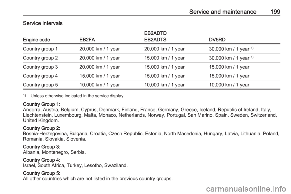
Service and maintenance199Service intervals
Engine codeEB2FA
EB2ADTD
EB2ADTS
DV5RD
Country group 120,000 km / 1 year20,000 km / 1 year30,000 km / 1 year 1)Country group 220,000 km / 1 year15,000 km / 1 year30,000 km / 1 year 1)Country group 320,000 km / 1 year15,000 km / 1 year15,000 km / 1 yearCountry group 415,000 km / 1 year15,000 km / 1 year15,000 km / 1 yearCountry group 510,000 km / 1 year10,000 km / 1 year10,000 km / 1 year1)
Unless otherwise indicated in the service display.Country Group 1:
Andorra, Austria, Belgium, Cyprus, Denmark, Finland, France, Germany, Greece, Iceland, Republic of Ireland, Italy, Liechtenstein, Luxembourg, Malta, Monaco, Netherlands, Norway, Portugal, San Marino, Spain, Sweden, Switzerland,
United Kingdom.Country Group 2:
Bosnia-Herzegovina, Bulgaria, Croatia, Czech Republic, Estonia, North Macedonia, Hungary, Latvia, Lithuania, Poland,
Romania, Slovakia, Slovenia.Country Group 3:
Albania, Montenegro, Serbia.Country Group 4:
Israel, South Africa, Turkey, Lesotho, Swaziland.Country Group 5:
All other countries which are not listed in the previous country groups.