warning OPEL CROSSLAND X 2019 Manual user
[x] Cancel search | Manufacturer: OPEL, Model Year: 2019, Model line: CROSSLAND X, Model: OPEL CROSSLAND X 2019Pages: 263, PDF Size: 8.11 MB
Page 57 of 263
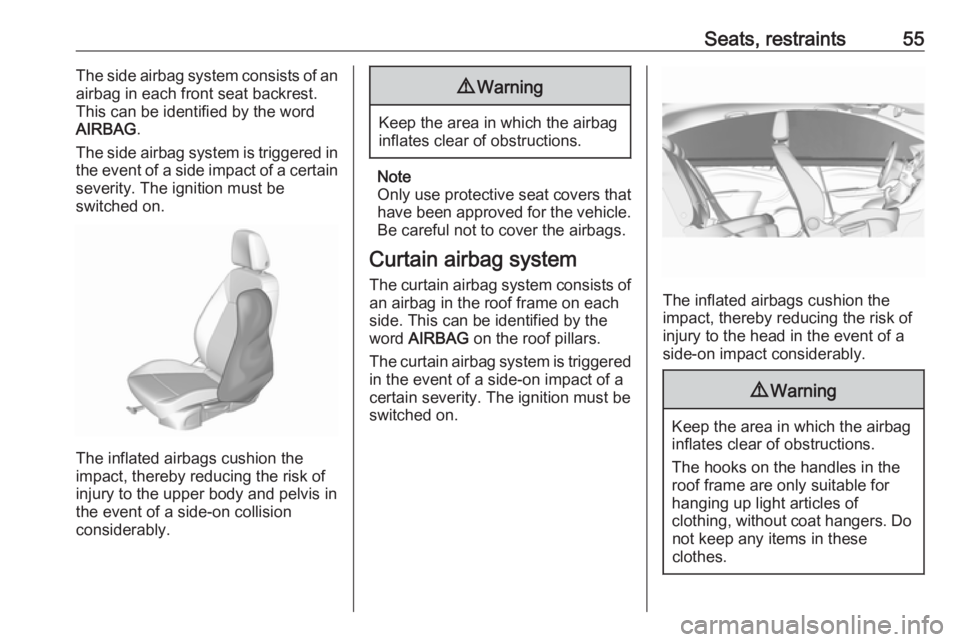
Seats, restraints55The side airbag system consists of an
airbag in each front seat backrest.
This can be identified by the word
AIRBAG .
The side airbag system is triggered in
the event of a side impact of a certain severity. The ignition must be
switched on.
The inflated airbags cushion the
impact, thereby reducing the risk of
injury to the upper body and pelvis in
the event of a side-on collision
considerably.
9 Warning
Keep the area in which the airbag
inflates clear of obstructions.
Note
Only use protective seat covers that have been approved for the vehicle.Be careful not to cover the airbags.
Curtain airbag system
The curtain airbag system consists of an airbag in the roof frame on each
side. This can be identified by the
word AIRBAG on the roof pillars.
The curtain airbag system is triggered
in the event of a side-on impact of a
certain severity. The ignition must be
switched on.
The inflated airbags cushion the
impact, thereby reducing the risk of
injury to the head in the event of a
side-on impact considerably.
9 Warning
Keep the area in which the airbag
inflates clear of obstructions.
The hooks on the handles in the
roof frame are only suitable for
hanging up light articles of
clothing, without coat hangers. Do not keep any items in these
clothes.
Page 65 of 263
Storage63StorageStorage compartments................63
Glovebox ................................... 63
Cupholders ................................ 63
Centre console storage .............64
Load compartment .......................64
Load compartment cover ...........67
Rear floor storage cover ............67
Lashing eyes ............................. 68
Warning triangle ........................69
First aid kit ................................. 69
Roof rack system .........................70
Roof rack ................................... 70
Loading information .....................70Storage compartments9Warning
Do not store heavy or sharp
objects in the storage
compartments. Otherwise, the
storage compartment lid could
open and vehicle occupants could be injured by objects being thrown
around in the event of hard
braking, a sudden change in
direction or an accident.
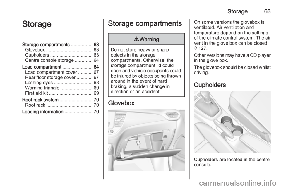
Glovebox
On some versions the glovebox is
ventilated. Air ventilation and
temperature depend on the settings
of the climate control system. The air
vent in the glove box can be closed
3 127.
Other versions may have a CD player
in the glove box.
The glovebox should be closed whilst driving.
Cupholders
Cupholders are located in the centre
console.
Page 67 of 263
Storage65the backrests onto the seat
cushion.
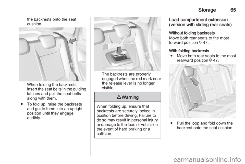
When folding the backrests,
insert the seat belts in the guiding
latches and pull the seat belts
along with them.
● To fold up, raise the backrests and guide them into an upright
position until they engage
audibly.
The backrests are properly
engaged when the red mark near the release lever is no longer
visible.
9 Warning
When folding up, ensure that
backrests are securely locked in
position before driving. Failure to
do so may result in personal injury or damage to the load or vehicle in the event of hard braking or a
collision.
Load compartment extension
(version with sliding rear seats)
Without folding backrests
Move both rear seats to the most
forward position 3 47.
With folding backrests ● Move both rear seats to the most
rearward position 3 47.
● Pull the loop and fold down the
backrest onto the seat cushion.
Page 71 of 263
Storage69Warning triangle
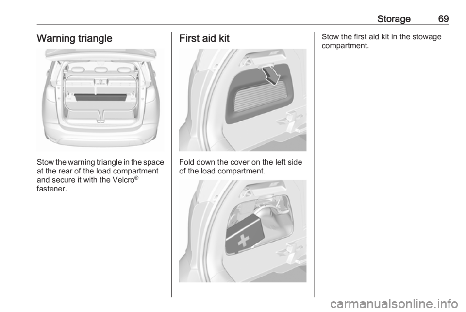
Stow the warning triangle in the space
at the rear of the load compartment
and secure it with the Velcro ®
fastener.
First aid kit
Fold down the cover on the left side
of the load compartment.
Stow the first aid kit in the stowage
compartment.
Page 73 of 263
Storage71● Do not allow the load to protrudeabove the upper edge of the
backrests.
● Do not place any objects on the load compartment cover or the
instrument panel, and do not
cover the sensor on top of the instrument panel.
● The load must not obstruct the operation of the pedals, parking
brake and gear selector, or
hinder the freedom of movement
of the driver. Do not place any
unsecured objects in the interior.
● Do not drive with an open load compartment.9Warning
Always make sure that the load in
the vehicle is securely stowed.
Otherwise objects can be thrown
around inside the vehicle and
cause personal injury or damage
to the load or car.
● The payload is the difference between the permitted gross
vehicle weight (see identification
plate 3 233) and the EC kerb
weight.
To calculate the payload, enter
the data for your vehicle in the
weights table at the front of this
manual.
The EC kerb weight includes
weights for the driver (68 kg),
luggage (7 kg) and all fluids (fuel
tank 90% full).
Optional equipment and
accessories increase the kerb
weight.
● Driving with a roof load increases
the sensitivity of the vehicle to
cross-winds and has a
detrimental effect on vehicle
handling due to the vehicle's
higher centre of gravity.
Distribute the load evenly and secure it properly with retaining
straps. Adjust the tyre pressure
and vehicle speed according to
the load conditions. Check and
retighten the straps frequently.
Do not drive faster than
120 km/h.The permissible roof load is
60 kg. The roof load is the
combined weight of the roof rack and the load.
Page 74 of 263
72Instruments and controlsInstruments and
controlsControls ....................................... 73
Steering wheel adjustment ........73
Steering wheel controls .............73
Heated steering wheel ...............73
Horn ........................................... 74
Windscreen wiper and washer ..74
Rear window wiper and washer ...................................... 76
Outside temperature ..................76
Clock ......................................... 77
Power outlets ............................. 77
Inductive charging .....................78
Cigarette lighter ......................... 79
Ashtrays .................................... 79
Warning lights, gauges and indi‐ cators ........................................... 80
Instrument cluster ......................80
Speedometer ............................. 84
Odometer .................................. 84
Trip odometer ............................ 84
Tachometer ............................... 84
Fuel gauge ................................ 85
Fuel selector .............................. 85Engine coolant temperature
gauge ....................................... 86
Engine oil level monitor .............87
Service display .......................... 87
Control indicators ......................88
Turn lights .................................. 88
Seat belt reminder .....................89
Airbag and belt tensioners .........89
Airbag deactivation ....................89
Charging system .......................90
Malfunction indicator light ..........90
Service vehicle soon .................90
Stop engine ............................... 90
System check ............................ 90
Brake and clutch system ...........91
Parking brake ............................ 91
Antilock brake system (ABS) .....91
Gear shifting .............................. 91
Lane departure warning ............91
Electronic Stability Control and Traction Control system ...........92
Electronic Stability Control and Traction Control system off ......92
Engine coolant temperature ......92
Preheating ................................. 92
Exhaust filter .............................. 92
AdBlue ....................................... 92
Deflation detection system ........93
Engine oil pressure ....................93
Low fuel ..................................... 93Autostop.................................... 93
Exterior light .............................. 93
Low beam .................................. 94
High beam ................................. 94
High beam assist .......................94
Front fog lights ........................... 94
Rear fog light ............................. 94
Rain sensor ............................... 94
Cruise control ............................ 94
Side blind spot alert ...................94
Active emergency braking .........94
Speed limiter ............................. 94
Door open .................................. 94
Displays ....................................... 95
Driver Information Centre ..........95
Info Display ................................ 97
Head-up display ........................99
Vehicle messages ......................101
Warning chimes .......................101
Battery voltage ........................ 101
Vehicle personalisation ..............102
Telematics service .....................105
OnStar ..................................... 105
Page 78 of 263
76Instruments and controlsPull lever. Washer fluid is sprayed
onto the windscreen and the wiper wipes a few times.
Washer fluid 3 191.
Rear window wiper and washer
Rear window wiper
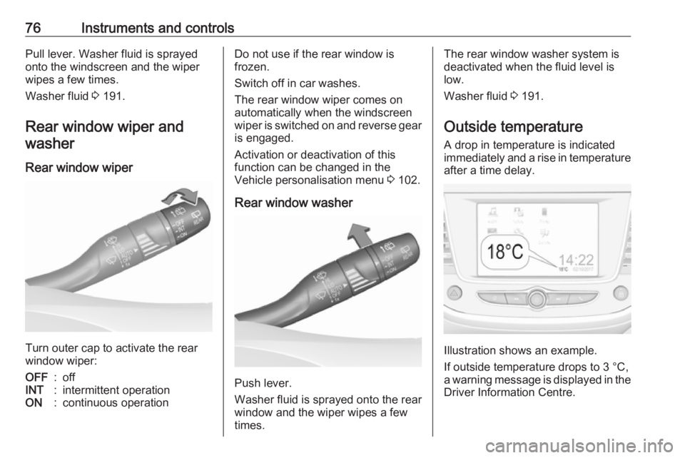
Turn outer cap to activate the rear
window wiper:
OFF:offINT:intermittent operationON:continuous operationDo not use if the rear window is
frozen.
Switch off in car washes.
The rear window wiper comes on
automatically when the windscreen
wiper is switched on and reverse gear
is engaged.
Activation or deactivation of this
function can be changed in the
Vehicle personalisation menu 3 102.
Rear window washer
Push lever.
Washer fluid is sprayed onto the rear
window and the wiper wipes a few
times.
The rear window washer system is
deactivated when the fluid level is
low.
Washer fluid 3 191.
Outside temperature A drop in temperature is indicated
immediately and a rise in temperature
after a time delay.
Illustration shows an example.
If outside temperature drops to 3 °C,
a warning message is displayed in the Driver Information Centre.
Page 79 of 263
Instruments and controls779Warning
The road surface may already be
icy even though the display
indicates a few degrees above
0 °C.
Clock
Date and time are shown in the
Info Display 3 97.
Setting date and time, see
Infotainment manual.
Power outlets
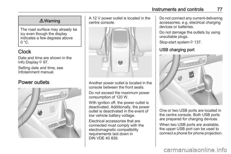
A 12 V power outlet is located in the
centre console.
Another power outlet is located in the console between the front seats.
Do not exceed the maximum power
consumption of 120 W.
With ignition off, the power outlet is deactivated. Additionally, the poweroutlet is deactivated in the event of
low vehicle battery voltage.
Electrical accessories that are
connected must comply with the
electromagnetic compatibility
requirements laid down in
DIN VDE 40 839.
Do not connect any current-delivering
accessories, e.g. electrical charging
devices or batteries.
Do not damage the outlets by using
unsuitable plugs.
Stop-start system 3 137.
USB charging port
One or two USB ports are located in
the centre console. Both USB ports
are prepared for charging devices.
When two USB ports are available,
the upper USB port can be used to
connect a phone for phone projection.
Page 80 of 263
78Instruments and controlsNote
The sockets must always be kept
clean and dry.
Inductive charging9 Warning
Inductive charging can affect the
operation of implanted
pacemakers or other medical
devices. If applicable, seek
medical advice before using the
inductive charging device.
9 Warning
Remove any metal objects from
the charging device before
charging a mobile device, as these objects could become very hot.
To charge a device, the ignition must
be switched on.
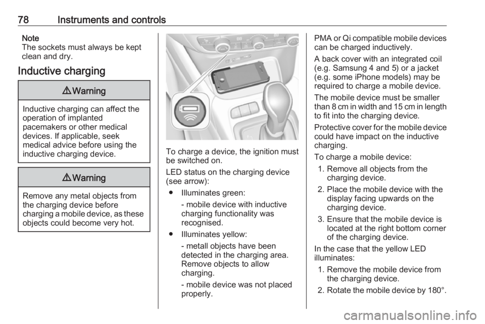
LED status on the charging device (see arrow):
● Illuminates green: - mobile device with inductivecharging functionality was
recognised.
● Illuminates yellow: - metall objects have been
detected in the charging area.
Remove objects to allow
charging.
- mobile device was not placed
properly.
PMA or Qi compatible mobile devices can be charged inductively.
A back cover with an integrated coil (e.g. Samsung 4 and 5) or a jacket
(e.g. some iPhone models) may be
required to charge a mobile device.
The mobile device must be smaller
than 8 cm in width and 15 cm in length
to fit into the charging device.
Protective cover for the mobile device could have impact on the inductive
charging.
To charge a mobile device: 1. Remove all objects from the charging device.
2. Place the mobile device with the display facing upwards on the
charging device.
3. Ensure that the mobile device is located at the right bottom corner
of the charging device.
In the case that the yellow LED
illuminates:
1. Remove the mobile device from the charging device.
2. Rotate the mobile device by 180°.
Page 82 of 263
80Instruments and controlsWarning lights, gauges
and indicators
Instrument cluster
Depending on the version, two
instrument clusters are available: