automatic transmission OPEL FRONTERA 1998 Owner's Manual
[x] Cancel search | Manufacturer: OPEL, Model Year: 1998, Model line: FRONTERA, Model: OPEL FRONTERA 1998Pages: 6000, PDF Size: 97 MB
Page 1275 of 6000

6E–158
ENGINE DRIVEABILITY AND EMISSIONS
Diagnostic Trouble Code (DTC) P0172 Fuel Trim System Rich Bank 1
D06RW030
Circuit Description
To provide the best possible combination of driveability,
fuel economy, and emission control, a “closed loop”
air/fuel metering system is used. While in “closed loop,”
the powertrain control module (PCM) monitors the Bank 1
heated oxygen sensors (HO2S) 1 and Bank 2 HO2S 1
signals and adjusts fuel delivery based upon the HO2S
signal voltages. A change made to fuel delivery will be
indicated by the long and short term fuel trim values which
can be monitored with a Tech 2. Ideal fuel trim values are
around 0%; if the HO2S signals are indicating a lean
condition the PCM will add fuel, resulting in fuel trim
values above 0%. If a rich condition is detected, the fuel
trim values will be below 0%, indicating that the PCM is
reducing the amount of fuel delivered. If an excessively
rich condition is detected on Bank 1, the PCM will set DTC
P0172.
The PCM’s maximum authority to control long term fuel
trim allows a range between –15% (automatic
transmission) or –12 (manual transmission) and +20%.The PCM’s maximum authority to control short term fuel
trim allows a range between –11% and +20%. The PCM
monitors fuel trim under various engine speed/load fuel
trim cells before determining the status of the fuel trim
diagnostic.
Conditions for Setting the DTC
No Tech 2 test is being run.
None of the following was set: EGR DTCs, HO2S
DTCs, (response, transition, open, low volts, no
activity), MAF DTCs, TPS DTCs, MAP DTCs, IAT
DTCs, canister purge DTCs, EVAP DTCs, injector
circuit DTCs, or misfire DTCs.
Engine coolant temperature is between 25C (77F)
and 100C (212F).
Intake air temperature is between –40C (–40F) and
120
C (248F).
Manifold absolute pressure is between 24 kPa and 99
kPa.
Throttle angle is steady below 95%.
Page 1279 of 6000

6E–162
ENGINE DRIVEABILITY AND EMISSIONS
Diagnostic Trouble Code (DTC) P0174 Fuel Trim System Lean Bank 2
D06RW031
Circuit Description
To provide the best possible combination of driveability,
fuel economy, and emission control, a “closed loop”
air/fuel metering system is used. While in “closed loop,”
the powertrain control module (PCM) monitors the Bank 1
HO2S 1 and Bank 2 HO2S 1 signals and adjusts fuel
delivery based upon the HO2S signal voltages. A change
made to fuel delivery will be indicated by the long and
short term fuel trim values which can be monitored with a
Tech 2. Ideal fuel trim values are around 0%; if the HO2S
signals are indicating a lean condition the PCM will add
fuel, resulting in fuel trim values above 0%. If a rich
condition is detected, the fuel trim values will be below
0%, indicating that the PCM is reducing the amount of fuel
delivered. If an excessively lean condition is detected on
Bank 2, the PCM will set DTC P0174.
The PCM’s maximum authority to control long term fuel
trim allows a range between –15%(automatic
transmission) or –12%(manual transmission) and +20%.
The PCM monitors fuel trim under various enginespeed/load fuel trim cells before determining the status of
the fuel trim diagnostic.
Conditions for Setting the DTC
No Tech 2 test is being run.
None of the following DTCs are set: idle system, EGR,
HO2S, (response, transition, open, low volts, no
activity), MAF, TP sensor, MAP, IAT, canister purge,
EVAP, injector circuit, or misfire.
Engine coolant temperature is between 25C (77F)
and 100C (212F).
Intake air temperature is between –40C (–40F) and
120C (248F).
Manifold absolute pressure is between 24 kPa and 99
kPa.
Throttle angle is steady below 95%.
Vehicle speed is below 136 km/h (85 mph).
Engine speed is between 400 and 6,000 RPM.
Barometric pressure is greater than 72.5 kPa.
Mass air flow is between 2 g/second and 200 g/second.
Page 1283 of 6000

6E–166
ENGINE DRIVEABILITY AND EMISSIONS
Diagnostic Trouble Code (DTC) P0175 Fuel Trim System Rich Bank 2
D06RW031
Circuit Description
To provide the best possible combination of driveability,
fuel economy, and emission control, a “closed loop”
air/fuel metering system is used. While in “closed loop,”
the powertrain control module (PCM) monitors the Bank 1
HO2S 1 and Bank 2 HO2S 1 signals and adjusts fuel
delivery based upon the HO2S signal voltages. A change
made to fuel delivery will be indicated by the long and
short term fuel trim values which can be monitored with a
Tech 2. Ideal fuel trim values are around 0%; if the HO2S
signals are indicating a lean condition the PCM will add
fuel, resulting in fuel trim values above 0%. If a rich
condition is detected, the fuel trim values will be below
0%, indicating that the PCM is reducing the amount of fuel
delivered. If an excessively rich condition is detected on
Bank 2, the PCM will set DTC P0175.
The PCM’s maximum authority to control long term fuel
trim allows a range between –15%(automatic
transmission) or –12%(manual transmission) and +20%.
The PCM’s maximum authority to control short term fueltrim allows a range between –11% and +20%. The PCM
monitors fuel trim under various engine speed/load fuel
trim cells before determining the status of the fuel trim
diagnostic.
Conditions for Setting the DTC
No Tech 2 test is being run.
None of the following DTCs are set: idle system, EGR,
HO2S, (response, transition, open, low volts, no
activity), MAF, TPS, MAP, IAT, canister purge, EVAP,
injector circuit, or misfire.
Engine coolant temperature is between 25C (77F)
and 100C (212F).
Intake air temperature is between –40C (–40F) and
120
C (248F).
Manifold absolute pressure is between 24 kPa and 99
kPa.
Throttle angle is steady below 95%.
Vehicle speed is below 136 km/h (85 mph).
Engine speed is between 400 and 6,000 RPM.
Page 1358 of 6000

6E–241 ENGINE DRIVEABILITY AND EMISSIONS
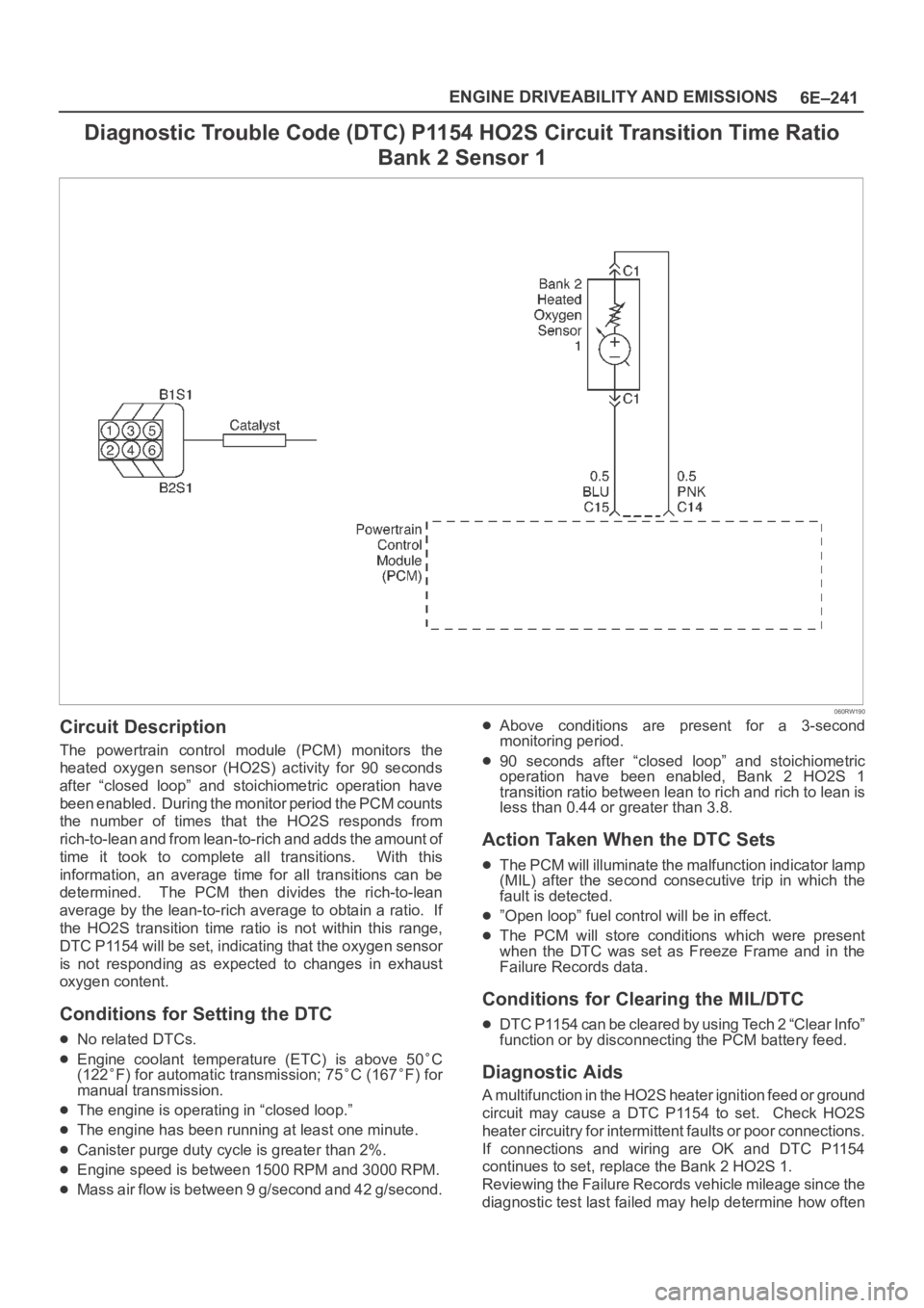
Diagnostic Trouble Code (DTC) P1154 HO2S Circuit Transition Time Ratio
Bank 2 Sensor 1
060RW190
Circuit Description
The powertrain control module (PCM) monitors the
heated oxygen sensor (HO2S) activity for 90 seconds
after “closed loop” and stoichiometric operation have
been enabled. During the monitor period the PCM counts
the number of times that the HO2S responds from
rich-to-lean and from lean-to-rich and adds the amount of
time it took to complete all transitions. With this
information, an average time for all transitions can be
determined. The PCM then divides the rich-to-lean
average by the lean-to-rich average to obtain a ratio. If
the HO2S transition time ratio is not within this range,
DTC P1154 will be set, indicating that the oxygen sensor
is not responding as expected to changes in exhaust
oxygen content.
Conditions for Setting the DTC
No related DTCs.
Engine coolant temperature (ETC) is above 50C
(122F) for automatic transmission; 75C (167F) for
manual transmission.
The engine is operating in “closed loop.”
The engine has been running at least one minute.
Canister purge duty cycle is greater than 2%.
Engine speed is between 1500 RPM and 3000 RPM.
Mass air flow is between 9 g/second and 42 g/second.
Above conditions are present for a 3-second
monitoring period.
90 seconds after “closed loop” and stoichiometric
operation have been enabled, Bank 2 HO2S 1
transition ratio between lean to rich and rich to lean is
less than 0.44 or greater than 3.8.
Action Taken When the DTC Sets
The PCM will illuminate the malfunction indicator lamp
(MIL) after the second consecutive trip in which the
fault is detected.
”Open loop” fuel control will be in effect.
The PCM will store conditions which were present
when the DTC was set as Freeze Frame and in the
Failure Records data.
Conditions for Clearing the MIL/DTC
DTC P1154 can be cleared by using Tech 2 “Clear Info”
function or by disconnecting the PCM battery feed.
Diagnostic Aids
A multifunction in the HO2S heater ignition feed or ground
circuit may cause a DTC P1154 to set. Check HO2S
heater circuitry for intermittent faults or poor connections.
If connections and wiring are OK and DTC P1154
continues to set, replace the Bank 2 HO2S 1.
Reviewing the Failure Records vehicle mileage since the
diagnostic test last failed may help determine how often
Page 1374 of 6000

6E–257 ENGINE DRIVEABILITY AND EMISSIONS
Diagnostic Trouble Code (DTC) P1618 Serial Peripheral Interface (SPI) PCM
Interprocessor Communication Error
Circuit Description
The serial peripheral interface (SPI) communication is
used internally by the PCM to send messages between
the engine processor and the automatic transmission
processor. Included in each message sent between the
two-processors is a checksum of the message. Both the
engine processor and automatic transmission processor
will compare this check sum value with the calculated
value. If the checksums don’t match, the processor will
view the new data as being corrupted and ignore the
values. The processor will then use the previous
message. The receiving processor will then send a
message to the sending processor informing it that it’s
last message was corrupted.
Conditions for Setting the DTC
Battery voltage is above 9.0 V for 2 seconds.
The PCM detects an internal program fault (check sum
of data communications error).
Check sum fault present for 3 out 6 seconds.
No TCM resets for 2 seconds.
Action Taken When the DTC Sets
The PCM will flash the “Check Trans” lamp the first
time the fault is detected.
The PCM will store conditions which were present
when the DTC was set as Freeze Frame and in the
Failure Records data.
The automatic transmission will operate in the “safety
mode” to protect the mechanical parts of the
transmission. Shift quality and/or gear changes may
not be normal.
Conditions for Clearing the MIL/DTC
DTC P1618 can be cleared by using the Tech 2 “Clear
Info” function or by disconnecting the PCM battery
feed.
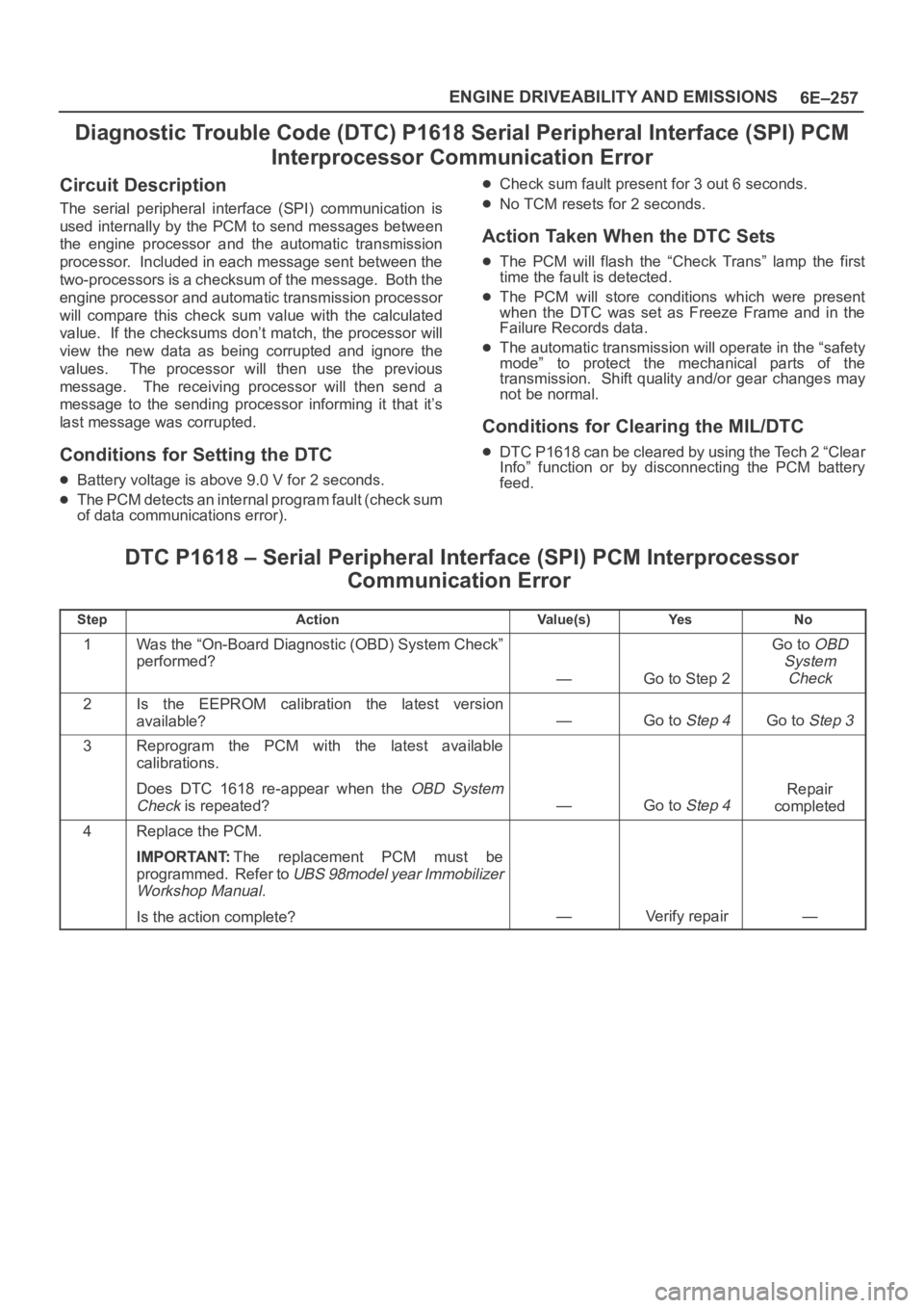
DTC P1618 – Serial Peripheral Interface (SPI) PCM Interprocessor
Communication Error
StepActionVa l u e ( s )Ye sNo
1Was the “On-Board Diagnostic (OBD) System Check”
performed?
—Go to Step 2
Go to OBD
System
Check
2Is the EEPROM calibration the latest version
available?
—Go to Step 4Go to Step 3
3Reprogram the PCM with the latest available
calibrations.
Does DTC 1618 re-appear when the
OBD System
Check
is repeated?—Go to Step 4
Repair
completed
4Replace the PCM.
IMPORTANT:The replacement PCM must be
programmed. Refer to
UBS 98model year Immobilizer
Workshop Manual.
Is the action complete?—Verify repair—
Page 1387 of 6000

6E–270
ENGINE DRIVEABILITY AND EMISSIONS
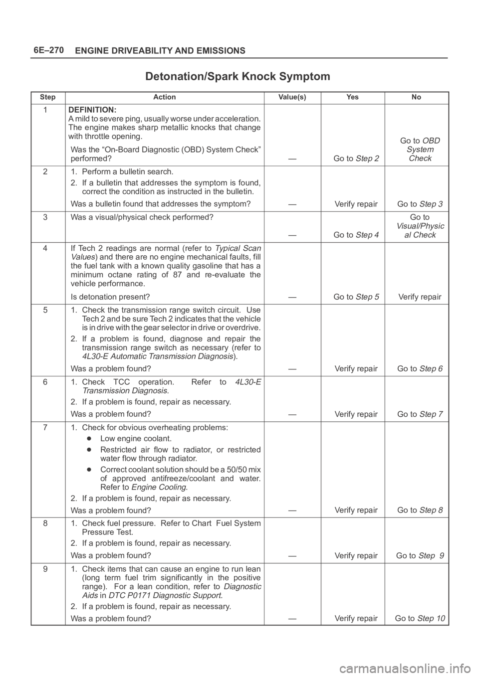
Detonation/Spark Knock Symptom
StepActionVa l u e ( s )Ye sNo
1DEFINITION:
A mild to severe ping, usually worse under acceleration.
The engine makes sharp metallic knocks that change
with throttle opening.
Was the “On-Board Diagnostic (OBD) System Check”
performed?
—Go to Step 2
Go to OBD
System
Check
21. Perform a bulletin search.
2. If a bulletin that addresses the symptom is found,
correct the condition as instructed in the bulletin.
Was a bulletin found that addresses the symptom?
—Verify repairGo to Step 3
3Was a visual/physical check performed?
—Go to Step 4
Go to
Visual/Physic
al Check
4If Tech 2 readings are normal (refer to Ty p i c a l S c a n
Va lu es
) and there are no engine mechanical faults, fill
the fuel tank with a known quality gasoline that has a
minimum octane rating of 87 and re-evaluate the
vehicle performance.
Is detonation present?
—Go to Step 5Verify repair
51. Check the transmission range switch circuit. Use
Tech 2 and be sure Tech 2 indicates that the vehicle
is in drive with the gear selector in drive or overdrive.
2. If a problem is found, diagnose and repair the
transmission range switch as necessary (refer to
4L30-E Automatic Transmission Diagnosis).
Was a problem found?
—Verify repairGo to Step 6
61. Check TCC operation. Refer to 4L30-E
Transmission Diagnosis
.
2. If a problem is found, repair as necessary.
Was a problem found?
—Verify repairGo to Step 7
71. Check for obvious overheating problems:
Low engine coolant.
Restricted air flow to radiator, or restricted
water flow through radiator.
Correct coolant solution should be a 50/50 mix
of approved antifreeze/coolant and water.
Refer to
Engine Cooling.
2. If a problem is found, repair as necessary.
Was a problem found?
—Verify repairGo to Step 8
81. Check fuel pressure. Refer to Chart Fuel System
Pressure Test.
2. If a problem is found, repair as necessary.
Was a problem found?
—Verify repairGo to Step 9
91. Check items that can cause an engine to run lean
(long term fuel trim significantly in the positive
range). For a lean condition, refer to
Diagnostic
Aids
in DTC P0171 Diagnostic Support.
2. If a problem is found, repair as necessary.
Was a problem found?
—Verify repairGo to Step 10
Page 1391 of 6000

6E–274
ENGINE DRIVEABILITY AND EMISSIONS
Rough, Unstable, or Incorrect Idle, Stalling Symptom
StepNo Ye s Va l u e ( s ) Action
171. Check ignition coils for cracks or carbon tracking.
2. If a problem is found, repair as necessary.
Was a problem found?
—Verify repairGo to Step 18
18Using Tech 2, monitor the throttle position (TP) angle
with the engine idling.
Is the TP angle at the specified value and steady?
0%Go to Step 19
Refer to DTC
P0123
for
further
diagnosis
191. Check the positive crankcase ventilation (PCV)
valve for proper operation. Refer to
Crankcase
Ventilation System
.
2. If a problem is found, repair as necessary.
Was a problem found?
—Verify repairGo to Step 20
201. Check the transmission range switch circuit. Use
Tech 2 and be sure Tech 2 indicates that the vehicle
is in drive with the gear selector in drive or overdrive.
2. If a problem is found, diagnose and repair the
transmission range switch as necessary (refer to
4L30-E Automatic Transmission Diagnosis).
Was a problem found?
—Verify repairGo to Step 21
211. Check for the following engine mechanical items.
Refer to
Engine Mechanical for diagnosis
procedures:
EGR valve mounted backward. Compare with
a known-good vehicle.
Low compression
Sticking or leaking valves
Worn camshaft lobe(s)
Camshaft drive belt slipped or stripped
Incorrect valve timing
Worn rocker arms
Broken valve springs
2. If a problem is found, repair as necessary.
Was a problem found?
—Verify repairGo to Step 22
221. Check for faulty motor mounts. Refer to Engine
Mechanical
for inspection of mounts.
2. If a problem is found, repair as necessary.
Was a problem found?
—Verify repairGo to Step 23
231. Review all diagnostic procedures within this table.
2. If all procedures have been completed and no
malfunctions have been found, review/inspect the
following:
Visual/physical inspection
Te c h 2 d a t a
Freeze Frame data/Failure Records buffer
All electrical connections within a suspected
circuit and/or system.
3. If a problem is found, repair as necessary.
Was a problem found?
—Verify repair
Contact
Te c h n i c a l
Assistance
Page 1401 of 6000

6E–284
ENGINE DRIVEABILITY AND EMISSIONS
Cuts Out, Misses Symptom
StepNo Ye s Va l u e ( s ) Action
171. Check ignition coils for cracks or carbon tracking.
2. If a problem is found, repair as necessary.
Was a problem found?
—Verify repairGo to Step 18
18Using Tech 2, monitor the TP angle with the engine
idling.
Is the TP angle at the specified value and steady?
0%Go to Step 19
Refer to DTC
P0123
for
further
diagnosis
191. Check the PCV valve for proper operation. Refer to
Crankcase Ventilation System.
2. If a problem is found, repair as necessary.
Was a problem found?
—Verify repairGo to Step 20
201. Check the transmission range switch circuit. Use
Tech 2 and be sure Tech 2 indicates that the vehicle
is in drive with the gear selector in drive or overdrive.
2. If a problem is found, diagnose and repair the
transmission range switch as necessary (refer to
4L30-E Automatic Transmission Diagnosis).
Was a problem found?
—Verify repairGo to Step 21
211. Check the following engine mechanical items.
Refer to
Engine Mechanical for diagnosis
procedures:
Low compression
Sticking or leaking valves
Worn camshaft lobe(s)
Camshaft drive belt slipped or stripped
Incorrect valve timing
Worn rocker arms
Broken valve springs
2. If a problem is found, repair as necessary.
Was a problem found?
—Verify repairGo to Step 22
221. Check for faulty motor mounts. Refer to Engine
Mechanical
for inspection of mounts.
2. If a problem is found, repair as necessary.
Was a problem found?
—Verify repairGo to Step 23
231. Review all diagnostic procedures within this table.
2. If all procedures have been completed and no
malfunctions have been found, review/inspect the
following:
Visual/physical inspection
Te c h 2 d a t a
Freeze Frame data/Failure Records butter
All electrical connections within a suspected
circuit and/or system
3. If a problem is found, repair as necessary.
Was a problem found?
—Verify repair
Contact
Te c h n i c a l
Assistance
Page 1405 of 6000

6E–288
ENGINE DRIVEABILITY AND EMISSIONS
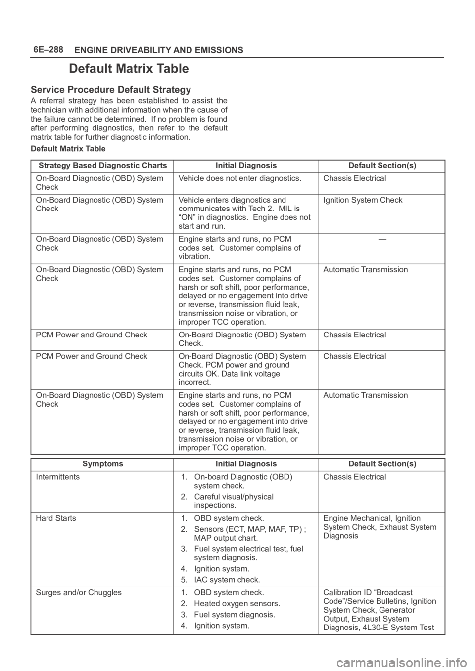
Default Matrix Table
Service Procedure Default Strategy
A referral strategy has been established to assist the
technician with additional information when the cause of
the failure cannot be determined. If no problem is found
after performing diagnostics, then refer to the default
matrix table for further diagnostic information.
Default Matrix Table
Strategy Based Diagnostic Charts
Initial DiagnosisDefault Section(s)
On-Board Diagnostic (OBD) System
CheckVehicle does not enter diagnostics.Chassis Electrical
On-Board Diagnostic (OBD) System
CheckVehicle enters diagnostics and
communicates with Tech 2. MIL is
“ON” in diagnostics. Engine does not
start and run.Ignition System Check
On-Board Diagnostic (OBD) System
CheckEngine starts and runs, no PCM
codes set. Customer complains of
vibration.—
On-Board Diagnostic (OBD) System
CheckEngine starts and runs, no PCM
codes set. Customer complains of
harsh or soft shift, poor performance,
delayed or no engagement into drive
or reverse, transmission fluid leak,
transmission noise or vibration, or
improper TCC operation.Automatic Transmission
PCM Power and Ground CheckOn-Board Diagnostic (OBD) System
Check.Chassis Electrical
PCM Power and Ground CheckOn-Board Diagnostic (OBD) System
Check. PCM power and ground
circuits OK. Data link voltage
incorrect.Chassis Electrical
On-Board Diagnostic (OBD) System
CheckEngine starts and runs, no PCM
codes set. Customer complains of
harsh or soft shift, poor performance,
delayed or no engagement into drive
or reverse, transmission fluid leak,
transmission noise or vibration, or
improper TCC operation.Automatic Transmission
SymptomsInitial DiagnosisDefault Section(s)
Intermittents1. On-board Diagnostic (OBD)
system check.
2. Careful visual/physical
inspections.Chassis Electrical
Hard Starts1. OBD system check.
2. Sensors (ECT, MAP, MAF, TP) ;
MAP output chart.
3. Fuel system electrical test, fuel
system diagnosis.
4. Ignition system.
5. IAC system check.Engine Mechanical, Ignition
System Check, Exhaust System
Diagnosis
Surges and/or Chuggles1. OBD system check.
2. Heated oxygen sensors.
3. Fuel system diagnosis.
4. Ignition system.Calibration ID “Broadcast
Code”/Service Bulletins, Ignition
System Check, Generator
Output, Exhaust System
Diagnosis, 4L30-E System Test
Page 1455 of 6000

6E–338
ENGINE DRIVEABILITY AND EMISSIONS
RPM. A failure in the MAF sensor or circuit will set DTC
P0101, DTC P0102, or DTC P0103.
0007
Manifold Absolute Pressure (MAP) Sensor
The manifold absolute pressure (MAP) sensor responds
to changes in intake manifold pressure (vacuum). The
MAP sensor signal voltage to the PCM varies from below
2 volts at idle (high vacuum) to above 4 volts with the
ignition ON, engine not running or at wide-open throttle
(low vacuum).
The MAP sensor is used to determine the following:
Manifold pressure changes while the linear EGR flow
test diagnostic is being run. Refer to
DTC P0401.
Engine vacuum level for other diagnostics.
Barometric pressure (BARO).
If the PCM detects a voltage that is lower than the
possible range of the MAP sensor, DTC P0107 will be set.
A signal voltage higher than the possible range of the
sensor will set DTC P0108. An intermittent low or high
voltage will set DTC P1107 or DTC P1106, respectively.
The PCM can detect a shifted MAP sensor. The PCM
compares the MAP sensor signal to a calculated MAP
based on throttle position and various engine load factors.
If the PCM detects a MAP signal that varies excessively
above or below the calculated value, DTC P0106 will set.
055RW004
Powertrain Control Module (PCM)
The powertrain control module (PCM) is located in the
passenger compartment below the center console. The
PCM controls the following:
Fuel metering system.
Transmission shifting (automatic transmission only).
Ignition timing.
On-board diagnostics for powertrain functions.
The PCM constantly observes the information from
various sensors. The PCM controls the systems that
affect vehicle performance. The PCM performs the
diagnostic function of the system. It can recognize
operational problems, alert the driver through the MIL
(Service Engine Soon lamp), and store diagnostic trouble
codes (DTCs). DTCs identify the problem areas to aid the
technician in making repairs.
This engine uses 2 different control modules:
IPCM-6KT for automatic transmission-equipped
vehicles.
ISFI-6 for manual transmission-equipped vehicles.
PCM Function
The PCM supplies either 5 or 12 volts to power various
sensors or switches. The power is supplied through
resistances in the PCM which are so high in value that a
test light will not light when connected to the circuit. In
some cases, even an ordinary shop voltmeter will not give
an accurate reading because its resistance is too low.
Therefore, a digital voltmeter with at least 10 megohms
input impedance is required to ensure accurate voltage
readings. Tool J 39200 meets this requirement. The PCM
controls output circuits such as the injectors, IAC, cooling
fan relays, etc., by controlling the ground or the power
feed circuit through transistors of following device.
Output Driver Module (ODM)