fuse box OPEL GT 2012 Owners Manual
[x] Cancel search | Manufacturer: OPEL, Model Year: 2012, Model line: GT, Model: OPEL GT 2012Pages: 190, PDF Size: 2.46 MB
Page 23 of 190

23Loc ks, do ors, windo ws
Fault
If the remote control d oe s not op erate
correctly , it may be due to the follow ing:
zThe range of the rem ote control has
been exceeded.
zRemote control b attery v olta ge is too
lo w . Se e " R em ot e co n t r ol ba t t er y
re place ment".
zFrequent, rep eated opera tion of the
re mote control outside the rece ption
ra nge of the vehicle (e .g. too far from the
vehicle, rem ote control is then no longer
recognised). See "Radio remote control
synchronisation".
zOve rloa ding the ce ntra l locking s yste m
by ope rating at freque nt inte rvals . The
power s upply m ay be interrupted for a
short time. The system is p rote cted by a
fus e in the fuse box – s ee page 1 41 .
zInt e r f er en ce f r o m h i g h er - p o w e r r a di o
waves from other sources.
To eliminate the cause of the fault, consult
a w orks hop.
O pen drive r’s door with key - s ee page 2 6. Rem ote control b atte ry rep lace me nt
Replace the battery in a ccord ance with the
cha pter " Servic e, M ainte nance" on
page 16 5 or w he n the range of the re mote
control be gins to decre ase .
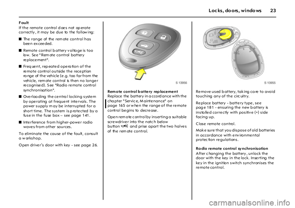
Ope n rem ote c ontrol by ins erting a suitable
scre wdrive r into the notc h below
buttonU and prise apart the two halve s
of the rem ote control.Re move used b attery, tak ing ca re to avoid
touching any of the circ uitry.
Re place battery - batte ry type , se e
pag e 181 - ensuring the new b attery is
insta lled correctly with positive (+) side
facing up.
Close remote control.
Mak e sure that you dispose of old batteries
in accordance with e nv ironme ntal
protec tion regulations.
Ra dio remote control sy nchronisation
After c hanging the battery , unlock the
door with the key in the lock. Inse rting the
key in the ignition switch synchronises the
re mote control.
Page 31 of 190

31Loc ks, do ors, windo ws
Ov erlo a d
If the windows are repe ated ly ope ra te d at
short intervals , the power supply is b rie fly
cut off.
The system is protected by a fuse in the fuse
box - s e e pa ge 1 4 1.Soft topLo w er i ng s of t to p
Only w ith v ehicle stationary.
Wi t h ve h i cl e p a r ked o n a l ev el s u r fa ce,
engage first or re ve rs e gea r, s witc h off
ignition and a pply hand b ra ke.
Plac e no obje cts in the area within the
lugg age compartm ent in which the s oft top
is to b e s to r ed.
Ensure that soft top canopy is dry b efore
low ering s oft top.
Ope n the lug gage compartme nt - s e e p a ge
26 .
9 Warning
Take care when lowe ring or raising the
soft top. Risk of injury. Vehicle passengers
s hould b e informed accordingly.
K ee p a close watch on the mov ing parts
whe n lowe ring or raising the soft top.
E ns ure that nothing be com es trapped as
the soft top is move d.
Page 97 of 190

97 Info tainment system
Troub leshooting
If y our Infotainment system does not
func tion as you would e xpe ct, plea se read
t h es e Op e r a t i ng In st r u ct i o ns ca re f u ll y a n d
g o t h r o ug h t he f o l l o w i ng c h ec k l i s t b e fo r e
contacting Custom er S ervices.
If y ou c annot find a solution to the
problem, we recommend that you consult
an O pel Servic e Partner.Error mes sage / s ympto m Pos sible cause / rem edy
Ge n e r a l
Di spl ay i s dar k. Vehic le’s ba tt er y i s weak (i f operated wit hout the eng ine runni ng );
S ee page 15 9 .
Di spl ay i s di ffi cul t to re ad. I nstrume nt i ll umina ti on i s set incor re ct ly ; S ee page 76 .
Inf otai nment sy stem cannot
be switched on either with the
Xe knob or wit h the i gni ti on k ey.Infotai nment system fuse or vehic le fusebox i s def ec ti ve.
Inc orre ct t ime on the disp lay S et t ime as spe ci fi ed on page 8 2 .
Aud io
Aud io pl ay back vol ume consta ntl y
decreases and c annot be adj usted .I nfotai nme nt syste m i s ov er heat ing. I nte rnal te mper ature re gul ator i s
ac ti ng to pro te ct th e In fo t ai n me n t s y s te m .
Recommend ati on: sw itc h the Infot ainment sy stem off.
Stored sta ti on c annot be sel ected
with the appropriate button
6.No re ce pt io n fo r s t ati o n cu rr en t ly.
Stored sta ti on not st ored wit h
stati on name.Broa dcast ing or ganisa ti on oc casi onall y se nds add it ional inf ormati on.
Tr y t o st ore it a gai n whe n the stat ion name appe ars on the di sp lay .
Poor reception when storing (frequency is displayed).
Broa dcast ing or ganisa ti on i s not tr ansmit ti ng RDS infor mati on
(f re quenc y i s disp lay ed ).
“CHE CK DIS C” appe ars on the
disp lay.A fte r l oadi ng a CD:
CD incorrectly inserted. CD la bel may be caught in the p layer.
Incompatible a udio CD inserted (DVD etc.).
CD sc ratc hed or ot her wi se da mage d.
I nser t an unda mage d, c ompati bl e C D wi th t he pr inte d si de upwa rds.
Duri ng CD pl ay back :
Temperature of Infotainment system too high.
Wai t unti l t he temperatur e of t he uni t has retur ned to nor mal.
Air is too humid. Wait for conditions to improve.
Road sur fac e i s une ve n. Whe n r oad sur face be comes smoothe r, CD
should p lay aga in.
“Ca li brat ion E rr or” ap pear s on t he
disp layI n fo tai n m e nt s ys te m h as n o t be en cal i brate d co r re ctl y. Ret u rn ve h ic le to
your retailer for service.
“Locked” app ear s on t he di spl ay. Elect roni c theft- deterrent feat ure ha s l ock ed up t he Infotai nment
s ys t em . Re tu rn v eh i cl e t o y o u r re tai l er fo r s e rv ice .
An ejected CD that ha s not been
acce pte d i s r et rac ted agai n by the
uni t when the igni ti on/unit is
switc hed of f.No e rro r.
Remove t he C D bef ore swi tc hing off t he i gni ti on/ Infot ai nment sy stem.
Page 133 of 190

13 3Self-help, vehicle care
Jum p start te rminals
In the eve nt of a discharged battery , the
jump start term inals locate d in the e ngine
compartme nt enable the vehicle to be
starte d without the ne ed to access the
batte ry.
The p ositive jum p start terminal is
ide ntified by a “+” sign on the re d
insulating cov er, located nex t to the e ngine
compartme nt fuse box.
O pen the re d insulating cov er to acce ss the
positiv e “+” te rmina l c onne ctor. E nsure the
red insulating cove r is latche d ba ck into
pos ition whe n not in us e.The nega tiv e jump start te rminal is
identified by a “GND (-)” s ign on a ground
bracke t, located below the e ngine be auty
cover.C onne ct the le ads in the orde r shown in the
illustration:
1 . Co n n ect o n e en d o f t h e f ir s t j u m p l e a d
to the positive te rminal 1 of the ba tte ry
providing the jump start (ide ntifie d by
"+" sign o n batte r y cas e o r ter min al) .
2 . Co n n ect t h e o t he r en d of th i s l ea d t o
the positiv e jump start te rminal 2 of the
vehicle with the d ischarge d batte ry
("+" sign).
3. Connect the first e nd of the other jump
lead to the neg ativ e te rminal 3 of the
battery providing the jump start
("–" sign).
4. Connect the other end of the second
jum p lea d 4 to the ne gative jum p sta rt
terminal ground brack et, id entifie d by
“GND (-)”.
Page 141 of 190

14 1Self-help, vehicle care
Electrical system
Fuses
The vehicle has two fuse boxes: one behind
a cov er on the rig ht-hand side of the
pas se nger com partment a nd anothe r in
the e ngine com partment.
It is advisable to carry a complete set of
fuses in the vehicle.
St o r e s p a r e f us e s o n t h e u nde r si d e o f t h e
engine c om partment fus e box cove r.
Opening the cover – see pa ge 144.
Before re placing a fus e, turn off the
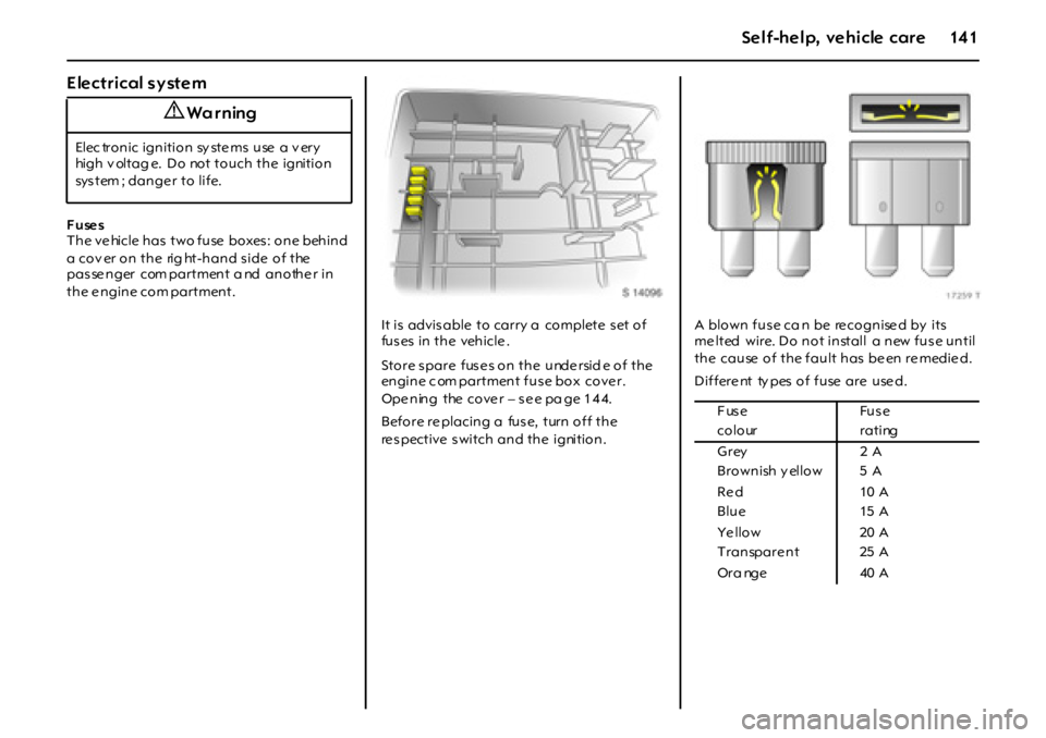
re spective switch and the ignition.A blown fus e ca n be re cognise d by its
me lted wire. Do not install a new fus e until
the cause of the fault has be en re medie d.
Differe nt ty pes of fuse are use d.
9 Wa r ning
Elec tronic ignition sy ste ms use a v ery
high v oltag e. Do not touch the ignition
sys t em ; da n g e r t o l i f e.
Fuse Fuse
c o l o ur r a t i ng
Grey 2 A
Brownish y ellow 5 A
Re d 10 A
Blue 15 A
Ye llo w 20 A
Transpare nt 25 A
Or a nge 40 A
Page 143 of 190

14 3Self-help, vehicle care
F u se s a n d t h e m o st i m po r t an t
circuits they protect
F use box in pa sse nge r compa rtme nt
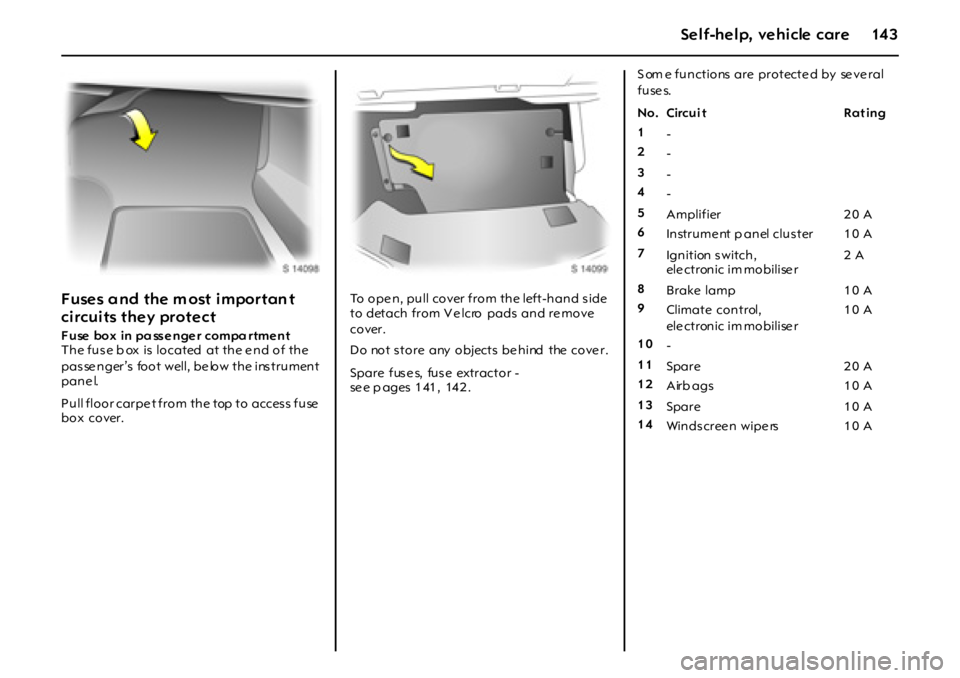
The fuse b ox is located at the e nd of the
pas se nger’s foot well, be low the ins trument
pane l.
Pull floor carpe t from the top to access fuse
box cover.To ope n, pull cover from the left-hand s ide
to detach from V e lcro pads and re move
cover.
Do not store any objects behind the cover.
Spare fus e s, fus e extractor -
se e p ages 1 41 , 14 2 . S om e functions are protecte d by se ve ral
f u se s.
No. Circui t Rat ing
1
-
2
-
3
-
4
-
5
Amplifier 2 0 A
6
Instrument p anel cluster 10 A
7
Ign ition s witch ,
ele ctronic im mobilise r2 A
8
Brake lamp 10 A
9
Climate control,
ele ctronic im mobilise r10 A
10
-
11
Spare 2 0 A
12
Airb ags 1 0 A
13
Spare 1 0 A
14
Wi n d s c r ee n w i p e rs 1 0 A
Page 144 of 190

144 Self-help, vehicle care
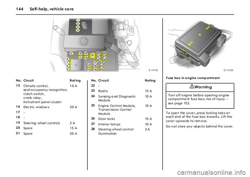
No. Circuit Rat ing
15
Climate co n tro l,
se at occupancy recognition,
clutch s witch,
crank relay ,
instrum ent panel cluster10 A
16
El ec tr i c w i nd ow s 3 0 A
17
-
18
-
19
St ee r i ng w h ee l co n tr o l s 2 A
20
Spare 1 5 A
21
Spare 2 0 ANo. Ci rcuit Rating
22
-
23
Rad io 15 A
24
S e nsing a nd Diagnos tic
Module10 A
25
Engine Control Module,
Transm iss ion Control
Module10 A
26
Door locks 15 A
27
In terio r lam ps 10 A
28
Steering wheel control
illumination2 AF use box in e ngine comp artm ent
To open the cover, press locking tabs a t
each end of the fuse box inwards. Lift the
cove r upwards to rem ove.
Do not store any ob jects behind the cover.
9 Wa r nin g
Turn off e ngine be fore opening e ngine
compartme nt fuse box; risk of injury –
se e page 15 2 .