clutch OPEL GT-R 1973 Service Manual
[x] Cancel search | Manufacturer: OPEL, Model Year: 1973, Model line: GT-R, Model: OPEL GT-R 1973Pages: 625, PDF Size: 17.22 MB
Page 5 of 625
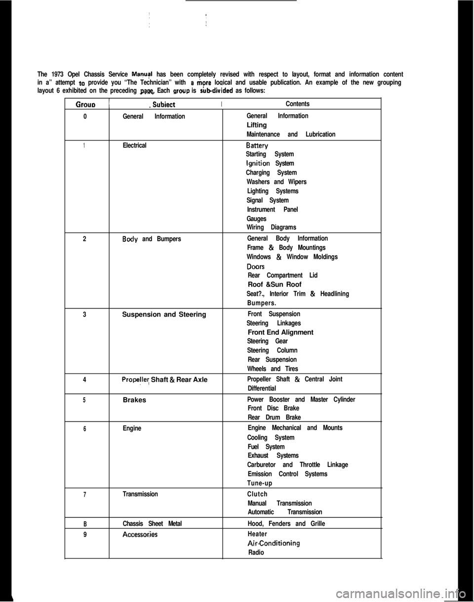
The 1973 Opel Chassis Service MayI has been completely revised with respect to layout, format and information content
in a” attempt
to provide you “The Technician” with a tiore logical and usable publication. An example of the new grouping
layout 6 exhibited on the preceding
page. Each wow is rubdivided as follows:
Grouo 1
_. _
Subiect IIContents.
0
General InformationIGeneral InformationLifting
Maintenance and Lubrication
1ElectricalBattery
Starting System
lgriition System
Charging System
Washers and Wipers
Lighting Systems
Signal SystemI
Instrument Panel
Gauges
Wiring Diagrams
2
Body and Bumpers:General Body InformationI
Frame & Body Mountings
Windows
& Window Moldings
DONS
Rear Compartment LidRoof &Sun Roof
Seat?., Interior Trim & Headlining
Bumpers.
3Suspension and Steering
Front Suspension
Steering Linkages1Front End Alignment
Steering Gear
Steering Column
Rear Suspension
Wheels and Tires
4
Propelley Shaft & Rear AxlePropeller Shaft & Central Joint
Differential
5Brakes ~Power Booster and Master Cylinder
Front Disc BrakeI
Rear Drum Brake
6EngineEngine Mechanical and Mounts
Cooling System
Fuel System
Exhaust Systems
Carburetor and Throttle Linkage
Emission Control Systems
Tune-up
7TransmissionClutch
Manual Transmission
Automatic Transmission
BChassis Sheet MetalHood, Fenders and Grille
9
Accessol;iesHeaterAirConditioning
Radio
Page 16 of 625
LUBRICATION AND MAINTENANCE OC-7SERVICESLUBE AND GENERAL MAINTENANCE
Vehicle operation under conditions such as heavy
dust, continuous short trips, use of other than un-
leaded or low lead fuels or pulling trailers, is not
considered normal use and therefore more frequent
maintenance will be required. Such additional
maintenance requirements are included where appli-
cable.
Engine OilChange each 4 months or
3,COO miles, whichever
occurs first, or each 2 months or
3,ooO miles when
the vehicle is operated under the following condi-
tions: (a) driving in dusty conditions, (b) trailer pull-
ing, (c) extensive idling or (d) short-trip operation at
freezing temperatures (with engine not thoroughly
warmed-up).Engine oils have a definite effect on ease of starting,
oil economy, combustion chamber deposits and en-
gine wear. It is recommended that a” oil which,
according to the label on the can is; (1) intended for
service SE and (2) passes car makers’ tests be used.
Oils confotming to these types contain detergent ad-
ditives. -
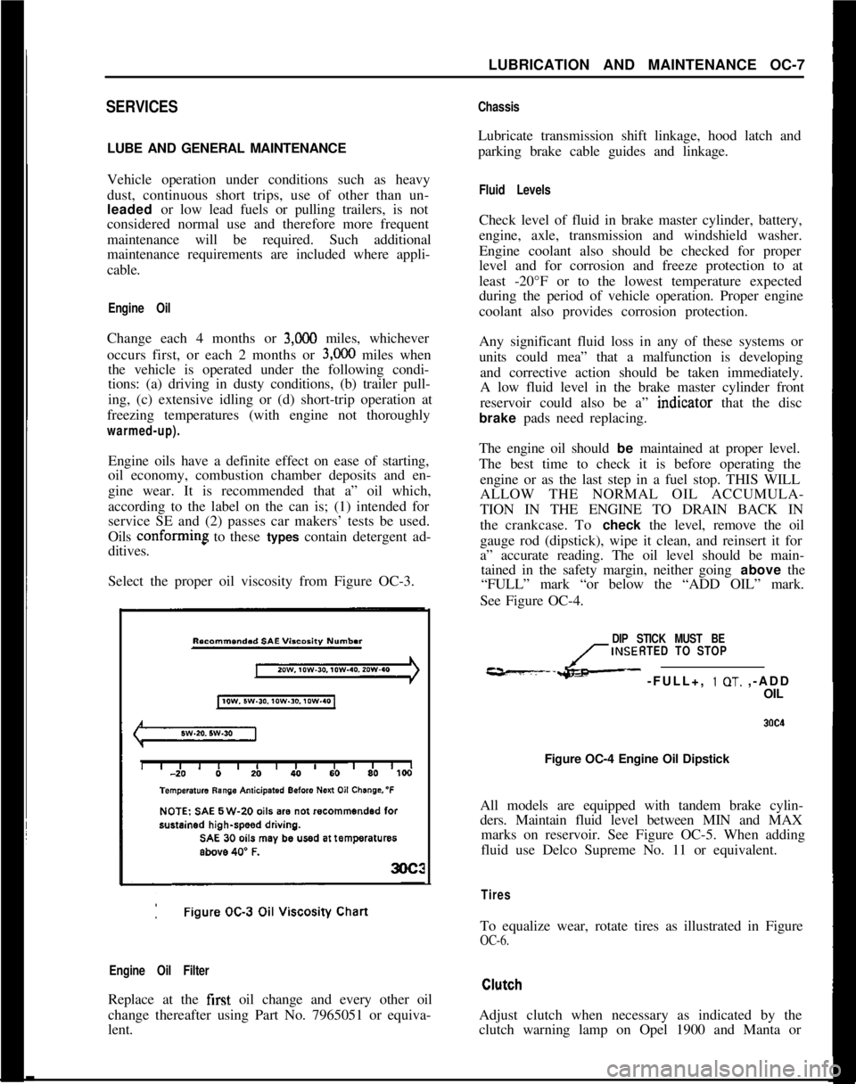
Select the proper oil viscosity from Figure OC-3.
Engine Oil FilterReplace at the first oil change and every other oil
change thereafter using Part No. 7965051 or equiva-
lent.
ChassisLubricate transmission shift linkage, hood latch and
parking brake cable guides and linkage.
Fluid LevelsCheck level of fluid in brake master cylinder, battery,
engine, axle, transmission and windshield washer.
Engine coolant also should be checked for proper
level and for corrosion and freeze protection to at
least -20°F or to the lowest temperature expected
during the period of vehicle operation. Proper engine
coolant also provides corrosion protection.
Any significant fluid loss in any of these systems or
units could mea” that a malfunction is developing
and corrective action should be taken immediately.
A low fluid level in the brake master cylinder front
reservoir could also be a” indtcator that the disc
brake pads need replacing.
The engine oil should be maintained at proper level.
The best time to check it is before operating the
engine or as the last step in a fuel stop. THIS WILL
ALLOW THE NORMAL OIL ACCUMULA-
TION IN THE ENGINE TO DRAIN BACK IN
the crankcase. To check the level, remove the oil
gauge rod (dipstick), wipe it clean, and reinsert it for
a” accurate reading. The oil level should be main-
tained in the safety margin, neither going above the
“FULL” mark “or below the “ADD OIL” mark.
See Figure OC-4.
DIP STICK MUST BE
INSERTED TO STOP
---L- -FULL+, 1 OT. ,-ADD
OIL
Figure OC-4 Engine Oil Dipstick
All models are equipped with tandem brake cylin-
ders. Maintain fluid level between MIN and MAX
marks on reservoir. See Figure OC-5. When adding
fluid use Delco Supreme No. 11 or equivalent.
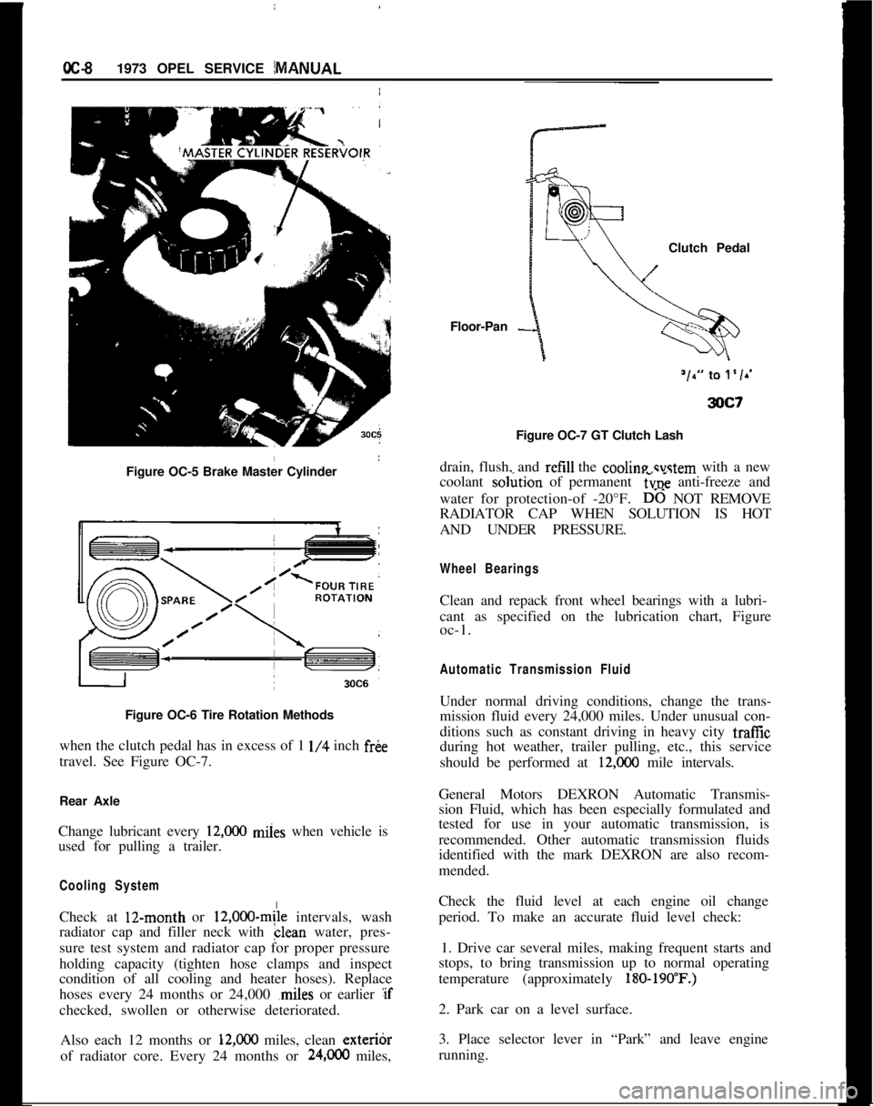
TiresTo equalize wear, rotate tires as illustrated in Figure
OC-6.Adjust clutch when necessary as indicated by the
clutch warning lamp on Opel 1900 and Manta or
Page 17 of 625
IoC-91973 OPEL SERVICE MANUAL
Figure OC-5 Brake Master Cylinder
I
Figure OC-6 Tire Rotation Methods
when the clutch pedal has in excess of 1
l/4 inch fr&
travel. See Figure OC-7.
Rear Axle
Change lubricant every
12,ooO miies when vehicle is
used for pulling a trailer.
Cooling SystemCheck at 12-month or
12,000~mile intervals, wash
radiator cap and filler neck with clean water, pres-
sure test system and radiator cap for proper pressure
holding capacity (tighten hose clamps and inspect
condition of all cooling and heater hoses). Replace
hoses every 24 months or 24,000 ,miles or earlier :if
checked, swollen or otherwise deteriorated.
Also each 12 months or
12,ooO miles, clean exteribr
of radiator core. Every 24 months or
24,OCO miles,Floor-Pan
-Clutch Pedal
Figure OC-7 GT Clutch Lash
drain, flush, and refill the cooline svstem with a new
coolant so&ion of permanent
6~; anti-freeze and
water for protection-of -20°F.
D-6 NOT REMOVE
RADIATOR CAP WHEN SOLUTION IS HOT
AND UNDER PRESSURE.
Wheel BearingsClean and repack front wheel bearings with a lubri-
cant as specified on the lubrication chart, Figure
oc-1.
Automatic Transmission FluidUnder normal driving conditions, change the trans-
mission fluid every 24,000 miles. Under unusual con-
ditions such as constant driving in heavy city traffic
during hot weather, trailer pulling, etc., this service
should be performed at
12,COO mile intervals.
General Motors DEXRON Automatic Transmis-
sion Fluid, which has been especially formulated and
tested for use in your automatic transmission, is
recommended. Other automatic transmission fluids
identified with the mark DEXRON are also recom-
mended.
Check the fluid level at each engine oil change
period. To make an accurate fluid level check:
1. Drive car several miles, making frequent starts and
stops, to bring transmission up to normal operating
temperature (approximately
180-190’F.)2. Park car on a level surface.
3. Place selector lever in “Park” and leave engine
running.
Page 31 of 625
1 B- 101973 OPEL SERVICE #MANUAL
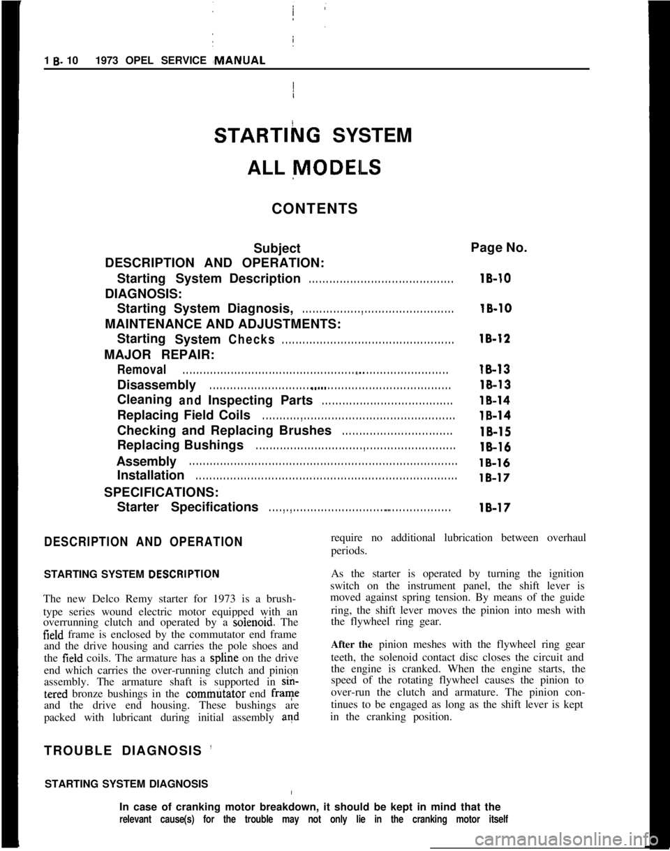
STARTlhG SYSTEM
/
ALL
MODEILS
CONTENTS
Subject
DESCRIPTION AND OPERATION:
Starting SystemDescription
. . . . . . . . . . . . . . . . . . . . . . . . . . . . . . . . . . . . \
. . . . . .
DIAGNOSIS:
Starting System Diagnosis,
. . . . . . . . . . . . . . . . . , . . . . . . . . . . . . . . . . . . \
. . . . . . . .
MAINTENANCE AND ADJUSTMENTS:Starting System
Checks. . . . . . . . . . . . . . . . . . . . . . . . . . . . . . . . . . . . \
. . . . . . . . . . . . . .
MAJOR REPAIR:
Removal. . . . . . . . . . . . . . . . . . . . . . . . . . . . . . . . . . . . \
. . . . . . . . . . . . . . . . . ., . . . . . . . . . . . . . . . . . . . . . . . . . .
Disassembly. . . . . . . . . . . . . . . . . . . . . . . . . . . . . . . a.... . . . . . . . . . . . . . . . . . . . . . . . . . . . . . . . . . . . .\
CleaningandInspecting Parts. . . . . . . . . . . . . . . . . . . . . . . . . . . . . . . . . . . . \
. .
Replacing Field Coils. . . . . . . . . . . , . . . . . . . . . . . . . . . . . . . . . . . . \
. . . . . . . . . . . . . . . . . . . .
Checking and Replacing Brushes. . . . . . . . . . . . . . . . . . . . . . . . . . . . . . . .
Replacing Bushings. . . . . . . . . . . . . . . . . . . . . . . . . . . . . . . , . . . . \
. . . . . . . . . . . . . . . . . . . . . .
Assembly. . . . . . . . . . . . . . . . . . . . . . . . . . . . . . . . . . . . \
. . . . . . . . . . . . . . . . . . . . . . . . . . . . . . . . . . . . \
. . . . . .
Installation. . . . . . . . . . . . . . . . . . . . . . . . . . . . . . . . . . . . \
. . . . . . . . . . . . . . . . . . . . . . . . . . . . . . . . . . . . \
. . . .
SPECIFICATIONS:
Starter Specifications
. . . . , . , . . . . . . . . . . . . . . . . . . . . . . . . . . . . . . . . . . . . . . . . . . . . . . .
Page No.
lB-10
16-10
18-12
18-13
18-13
18-14
18-14
16-15
18-16
lB-16
18-17
18-17
DESCRIPTION AND OPERATION
STARTING SYSTEM DESCRlPTlqN
The new Delco Remy starter for 1973 is a brush-
type series wound electric motor equipped with an
overrunning clutch and operated by a
soienoid. The
field frame is enclosed by the commutator end frame
and the drive housing and carries the pole shoes and
the
field coils. The armature has a spline on the drive
end which carries the over-running clutch and pinion
assembly. The armature shaft is supported in
sin-
tered bronze bushings in the commtitator end frame
and the drive end housing. These bushings are
packed with lubricant during initial assembly
and
TROUBLE DIAGNOSIS ’
STARTING SYSTEM DIAGNOSIS/
require no additional lubrication between overhaul
periods.
As the starter is operated by turning the ignition
switch on the instrument panel, the shift lever is
moved against spring tension. By means of the guide
ring, the shift lever moves the pinion into mesh with
the flywheel ring gear.
After the pinion meshes with the flywheel ring gear
teeth, the solenoid contact disc closes the circuit and
the engine is cranked. When the engine starts, the
speed of the rotating flywheel causes the pinion to
over-run the clutch and armature. The pinion con-
tinues to be engaged as long as the shift lever is kept
in the cranking position.
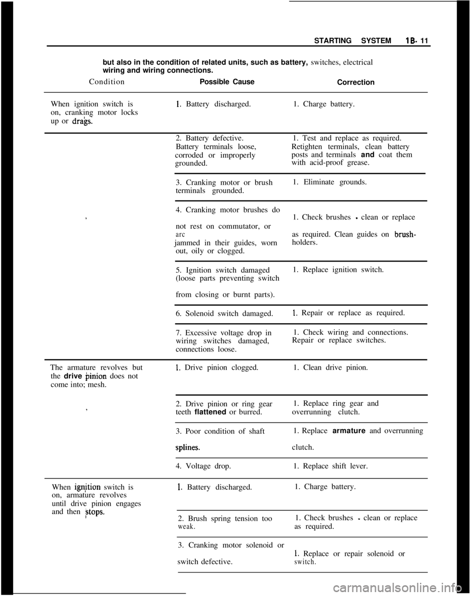
In case of cranking motor breakdown, it should be kept in mind that the
relevant cause(s) for the trouble may not only lie in the cranking mot\
or itself
Page 32 of 625
I
STARTING SYSTEMlB- 11
but also in the condition of related units, such as battery, switches, electrical
wiring and wiring connections.
ConditionPossible Cause
Correction
When ignition switch is1. Battery discharged.1. Charge battery.
on, cranking motor locks
up or
dra’gs.2. Battery defective.1. Test and replace as required.
Battery terminals loose,Retighten terminals, clean battery
corroded or improperlyposts and terminals and coat them
grounded.with acid-proof grease.
3. Cranking motor or brush1. Eliminate grounds.
terminals grounded.
I
4. Cranking motor brushes do
,
1. Check brushes
- clean or replace
not rest on commutator, or
arcas required. Clean guides on brush-
jammed in their guides, wornholders.
out, oily or clogged.
5. Ignition switch damaged1. Replace ignition switch.
(loose parts preventing switch
I
from closing or burnt parts).
6. Solenoid switch damaged.
1. Repair or replace as required.
7. Excessive voltage drop in1. Check wiring and connections.
wiring switches damaged,Repair or replace switches.
connections loose.
The armature revolves but
1. Drive pinion clogged.1. Clean drive pinion.
the drive binion does not
come into; mesh.
2. Drive pinion or ring gear1. Replace ring gear and
,
teeth flattened or burred.overrunning clutch.
I
3. Poor condition of shaft1. Replace armature and overrunningsplines.clutch.
4. Voltage drop.1. Replace shift lever.
When ignjtion switch is
1. Battery discharged.1. Charge battery.
on, armature revolves
until drive pinion engages
and then
Btops.2. Brush spring tension too1. Check brushes - clean or replace
weak.as required.
3. Cranking motor solenoid or
1. Replace or repair solenoid or
switch defective.
switch.
Page 33 of 625
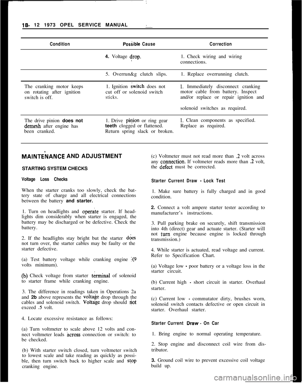
19- 12 1973 OPEL SERVICE MANUAL :ConditionPosiible CauseCorrection4. Voltage drop.1. Check wiring and wiring
connections.
5. Overrun&g clutch slips.1. Replace overrunning clutch.
The cranking motor keeps
on rotating after ignition
switch is off.1. Ignition
{witch does not
cut off or solenoid switch
sticks.
1, Immediately disconnect cranking
motor cable from battery. Inspect
and/or replace or repair ignition and
solenoid switches as required.
The drive pinion does notdemesh after engine has
been cranked.1. Drive pinion or ring gear
1. Clean components as specified.
teeth clogged or flattened.Replace as required.
Return spring slack or broken.MAlNTEilANCE AND ADJUSTMENT
/
STARTING SYSTEM CHECKS
Voltage Loss ChecksWhen the starter cranks too slowly, check the bat-
tery state of charge and all electrical connections
between the battery and starter.
1. Turn on headlights and
opera’te starter. If head-
lights dim considerably when starter is engaged, the
battery may be discharged or be defective. Check the
battery.
2. If the headlights stay bright but the starter d&s
not turn over, the starter cables may be faulty or the
starter defective.
(a) Test battery voltage while cranking engine
1(9volts minimum).
(b) Check voltage from starter tkrminal of solenoid
to starter frame while cranking engine.
3. The difference in readings taken in Operations 2a
and 2b above represents the
volt& drop through the
cables and solenoid switch. Voltdge drop should
Gotexceed
.5 volt.
4. Locate excessive resistance as follows:
(a) Turn voltmeter to scale above 12 volts and con-
nect voltmeter leads
across connection or switch: to
be checked.
(b) With starter switch closed, turn voltmeter switch
to lowest scale and take reading as quickly as possi-
ble, then turn switch back to higher scale and stop
cranking engine.(c) Voltmeter must not read more than
.2 volt across
any
c:onnection. If voltmeter reads more than .2 volt,
the
d~efect must be corrected.
Starter Current Draw - Lock Test1. Make sure battery is fully charged and in good
condition.
2. Connect a volt ampere starter tester according to
manufacturer’s instructions.
3. Pull parking brake on securely, shift transmission
into 4th (direct) gear and actuate starter. (Starter will
not
t,urn engine because engine is locked through
transmission.)
4. While starter is actuated, read voltage and current.
Refer to Specification Chart.
(a) Voltage low
_ poor battery or a voltage loss in the
starter circuit.
(b) Current high
- short circuit in starter. Overhaul
starter.
(c) Current low
- commutator dirty, brushes worn,
solenoid switch contacts defective or open circuit in
starter. Overhaul starter.
Starter Current Draw. On Car1. Bring engine to normal operating temperature.
2. Stop engine and disconnect coil wire from dis-
tributor.
3. Ground coil wire to prevent excessive coil voltage
build up.
Page 35 of 625
lB- 14 1973 OPEL SERVICE MANUAL !
6. Remove shift lever shaft and: lift armature aid
shift lever assembly.
7. Drive back retaining ring on armature shaft. See
Figure
lB-5.
8. Take the lock ring, retaining ring, and
over&-
ning clutch and pinion off armature shaft. Cheqk
groove in shaft for burrs and remove with a soft tile.
Cleaning and Inspecting Parts
1. Clean and check all parts. Replace defective parts.
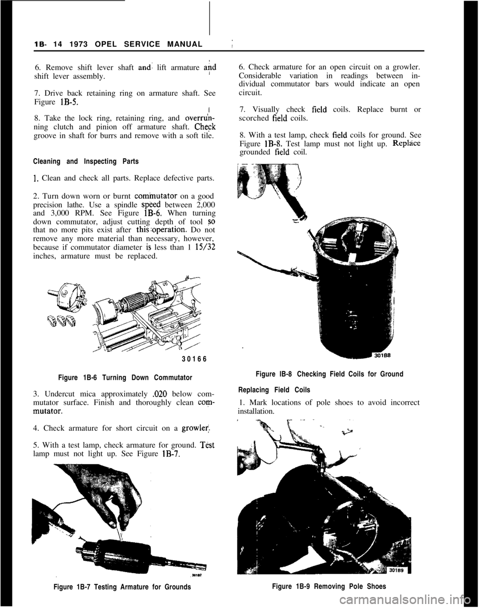
2. Turn down worn or burnt
cominutator on a good
precision lathe. Use a spindle
speed between 2,000
and 3,000 RPM. See Figure
lB-6. When turning
down commutator, adjust cutting depth of tool
so
that no more pits exist after this:operation. Do not
remove any more material than necessary, however,
because if commutator diameter
is less than 1 15/32
inches, armature must be replaced.
30166
Figure 1B-6 Turning Down Commutator
3. Undercut mica approximately ,020 below com-
mutator surface. Finish and thoroughly clean
corn-
mutator.
I
4. Check armature for short circuit on a
growler.
5. With a test lamp, check armature for ground.
Test
lamp must not light up. See Figure
IB-7.
Figure 1B-7 Testing Armature for Grounds
j
6. Check armature for an open circuit on a growler.
Considerable variation in readings between in-
dividual commutator bars would indicate an open
circuit.
7. Visually check
field coils. Replace burnt or
scorched
field coils.
8. With a test lamp, check
field coils for ground. See
Figure
IB-8. Test lamp must not light up. Replzice
grounded field coil.
Figure lB-8 Checking Field Coils for Ground
Replacing Field Coils
1. Mark locations of pole shoes to avoid incorrect
installation.
Figure 1B-9 Removing Pole Shoes
Page 76 of 625
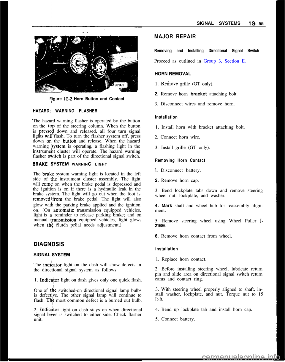
Tigure lG-2 Horn Button and Contact
HAZARD; WARNING FLASHER
The hazard warning flasher is operated by the button
on the
toi, of the steering column. When the button
is
press&@ down and released, all four turn signal
lights
WIU flash. To turn the flasher system off, press
down
oni the button and release. When the hazard
warning
hystem is operating, a flashing light in the
iristrumeht cluster will operate. The hazard warning
flasher
&itch is part of the directional signal switch.
BRAKE $YSTEM WARNING LIGHT
The brak; system warning light is located in the left
side of
tpe instrument cluster assembly. The light
will
come on when the brake pedal is depressed and
the ignition is on if there is a hydraulic leak in the
brake system. The light will go out when the foot is
removed!from the brake pedal. The light will also
glow with the parking brake applied and the ignition
on. (On
Iautomatic transmission equipped vehicles,
light is
a! reminder to release parking brake; and on
manual
fransmission equipped vehicles, light glows
when
the clutch pedal needs adjustment,)
I
DlAGNfXlS
SIGNAL SYSTEM
The indiLator light on the dash will show defects in
the directional signal system as follows:
1.
Indic
tie switched-on directional signal lamp bulbs
is defective. The other signal lamp will continue to
flash.
Thi most common defect is a burned out bulb.
2.
Indicdtor light on dash stays on when directional
signal
leier is switched to either side. Check flasher
unit. I
SIGNAL SYSTEMSlG- 55
MAJOR REPAIR
Removing and Installing Directional Signal Switch
Proceed as outlined in Group 3, Section E.
HORN REMOVAL
1. Remove grille (GT only).
2. Remove horn bracket attaching bolt.
3. Disconnect wires and remove horn.
Installation
1. Install horn with bracket attaching bolt.
2. Connect horn wire.
3. Install grille (GT only).
Removing Horn Contact
1. Disconnect battery.
2. Remove horn cap.
3. Bend lockplate tabs down and remove steering
wheel nut, lockplate, and washer.
4. Mark shaft and wheel hub for reassembly align-
ment.
5. Remove steering wheel using Wheel Puller
J-
21686.
6. Remove horn contact from wheel.
installation
1. Replace horn contact.
2. Before installing steering wheel, lubricate return
pin and slide area on directional signal switch return
cams and contact ring.
3. With steering wheel properly aligned to shaft, in-
stall washer, lockplate, and nut. Torque nut to 15
lb.ft.
4. Bend up lockplate tab and install horn cap.
5. Connect battery.
Page 283 of 625
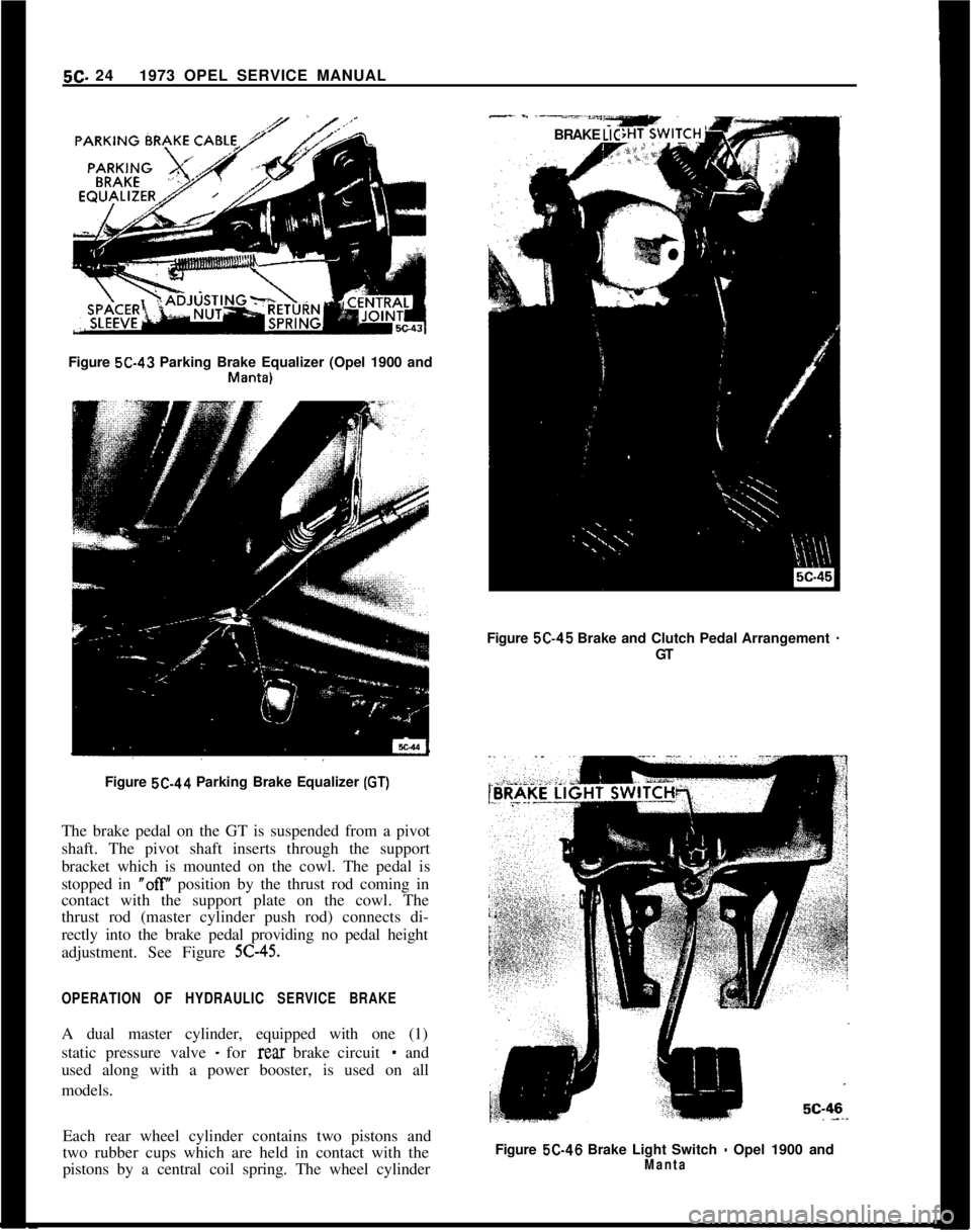
5C- 241973 OPEL SERVICE MANUAL-~ - -----*““YBRAKE LICFigure 5C-43 Parking Brake Equalizer (Opel 1900 and
Mallta)Figure 5C-45 Brake and Clutch Pedal Arrangement
-GT
Figure 5C-44 Parking Brake Equalizer
(GT)The brake pedal on the GT is suspended from a pivot
shaft. The pivot shaft inserts through the support
bracket which is mounted on the cowl. The pedal is
stopped in
“off position by the thrust rod coming in
contact with the support plate on the cowl. The
thrust rod (master cylinder push rod) connects di-
rectly into the brake pedal providing no pedal height
adjustment. See Figure
5C-45.
OPERATION OF HYDRAULIC SERVICE BRAKEA dual master cylinder, equipped with one (1)
static pressure valve
- for rear brake circuit - and
used along with a power booster, is used on all
models.
Each rear wheel cylinder contains two pistons and
two rubber cups which are held in contact with the
pistons by a central coil spring. The wheel cylinderFigure 5C-46 Brake Light Switch
- Opel 1900 andManta
Page 299 of 625
6A- 8 1973 OPEL SERVICE MANUAL
Actual adjustment is made by backing off adjusting
nut at the rocker arm until clearance exists between the valve stem, rocker arm, and lifter. Then slowly
tighten adjusting nut until clearance is eliminated.
When clearance is eliminated, turn adjusting nut one
full turn (clockwise). This positions the hydraulic
piston of the hydraulic lifter mid-point in its total
available travel, and no further adjustment is re-
quired.
MAJOR REPAIR
ENGINE ASSEMBLY REMOVAL AND
INSTALLATION
Removal (Opel 1900 and Manta)’
The engine assembly on the Opel 1900 and Manta
can be removed together with the transmission
through the top of the engine compartment.
1. Remove hood (scribe hood hinge to hood mount-
ing location).
2. Disconnect battery negative cable.
3. Drain coolant at lower radiator hose.
4. Remove upper and lower radiator hoses.
5. Remove radiator and fan
shrbud.
6. Disconnect heater hoses.
7. Disconnect brake booster
vacuum hose.
8. Remove air cleaner.
9. Disconnect electrical connections and accelerator
linkage. 10. Remove console.
11. Remove shift lever boot, plate, and shift lever.
12. Raise car on hoist.
13. Disconnect fuel line at pump.
14. Remove front stone shield.
15. Disconnect speedo-cable, back-up light switch,
and clutch cable.
16. Remove drive shaft. I
17. Disconnect exhaust pipe
ar$l bell housing sup-
port.
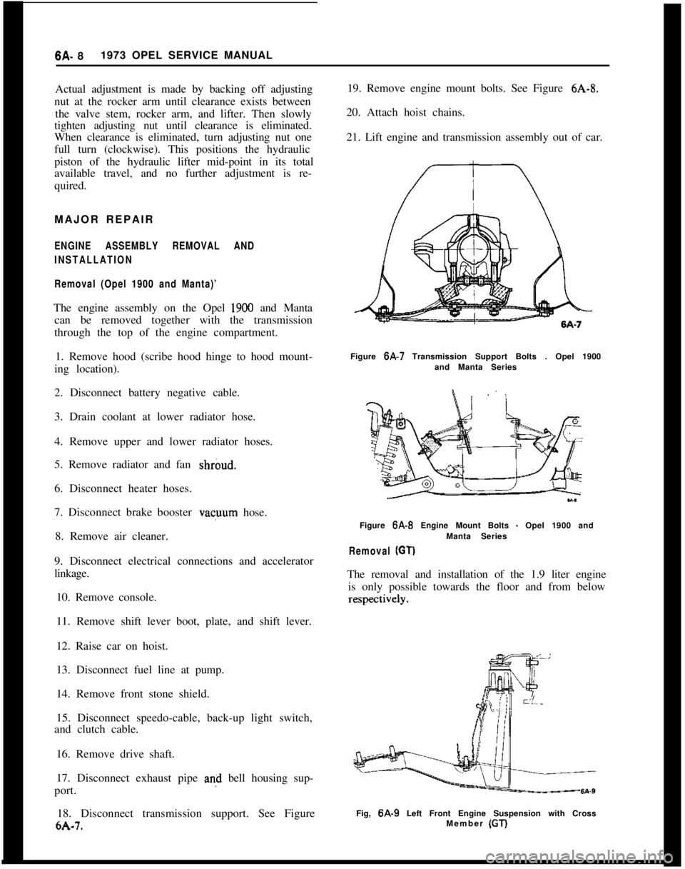
18. Disconnect transmission support. See Figure
6A-7. 19. Remove engine mount bolts. See Figure
6A-8.
20. Attach hoist chains.
21. Lift engine and transmission assembly out of car.
Figure 6A-7 Transmission Support Bolts . Opel 1900
and Manta Series
Figure
6A-B Engine Mount Bolts - Opel 1900 and
Manta Series
Removal (GT)
The removal and installation of the 1.9 liter engine is only possible towards the floor and from below
Fig, 6A-9 Left Front Engine Suspension with Cross
Member (GT)