battery OPEL INSIGNIA 2014 Manual user
[x] Cancel search | Manufacturer: OPEL, Model Year: 2014, Model line: INSIGNIA, Model: OPEL INSIGNIA 2014Pages: 321, PDF Size: 8.95 MB
Page 162 of 321
160Driving and operating
GeneralIf a higher gear is selected when
vehicle speed is too low, or a lower
gear when vehicle speed is too high,
the shift is not executed. This can
cause a message in the Driver
Information Centre.
In manual mode no automatic shifting
to a higher gear takes place at high
engine revolutions.
Electronic driving
programmes ■ Following a cold start, the operating
temperature programme increases engine speed to quickly bring the
catalytic converter to the required
temperature.
■ The automatic neutral shift function
automatically shifts to idling when
the vehicle is stopped with a
forward gear engaged and the
brake pedal is pressed.
■ When SPORT mode is engaged, the vehicle shifts at higher engine
speeds (unless cruise control is
on). SPORT mode 3 168.■ Special programmes automatically
adapt the shifting points when
driving up inclines or down hills.
■ When starting off in snowy or icy conditions or on other slippery
surfaces, the electronic
transmission control selects a
higher gear automatically.
Kickdown If the accelerator pedal is pressed
down completely in automatic mode, the transmission shifts to a lower gear
depending on engine speed.
Overheat protection
In the event of transmission-
overheating due to high outside
temperatures or sporty driving style,
the torque and the maximum speed of the engine can be temporarily
reduced.
Fault In the event of a fault a vehicle
message is displayed in the Driver
Information Centre. Vehicle
messages 3 116.The transmission no longer shifts
automatically. Continued travel is
possible with manual shifting.
Only the highest gear is available.
Depending on the fault, 2nd gear may also be available in manual mode.
Shift only when vehicle is stationary.
Have the cause of the fault remedied
by a workshop.
Interruption of power
supply
In the event of an interruption of
power supply, the selector lever
cannot be moved out of the P
position. The ignition key cannot be
removed from the ignition switch.
If the vehicle battery is discharged,
start the vehicle using jump leads
3 252.
If the vehicle battery is not the cause
of the fault, release the selector lever
and remove the ignition key from the
ignition switch.
Page 167 of 321

Driving and operating165
Do not operate electric parking brake
system too often without engine
running as this will discharge the vehicle battery.
Before leaving the vehicle, check the electric parking brake status. Control
indicator m 3 102.
Releasing
Switch on ignition. Keep foot brake
pedal depressed and then push
switch m.
Drive away function
Depressing clutch pedal (manual
transmission) or engaging drive gear
(automatic transmission) and then
depressing the accelerator pedal
releases the electric parking brake
automatically. This is not possible
when the switch is pulled at the same time.
This function also helps driving away
on inclines.
Aggressive drive away may reduce
life time of wear parts.Dynamic braking when vehicle is
moving
When the vehicle is moving and the
switch m is kept pulled, the electric
parking brake system will decelerate the vehicle, but will not apply
statically.
As soon as the switch m is released,
dynamic braking will be stopped.
Automatic applying
If the vehicle is equipped with
Automatic transmission and Adaptive cruise control is active, electric
parking brake is applied automatically
when vehicle is stopped by the
system for more than 2 minutes.
Parking brake releases automatically
after moving off.
Functionality check
When the vehicle is not moving, the
electric parking brake might be
applied automatically. This is done to
check the system.Fault
Failure mode of electric parking brake
is indicated by a control indicator j
and by a vehicle message which is
displayed in the Driver Information Centre. Vehicle messages 3 116.
Apply electric parking brake: pull and hold the switch m for more than
5 seconds. If control indicator m
illuminates, electric parking brake is
applied.
Release electric parking brake: push and hold the switch m for more than
2 seconds. If control indicator m
extinguishes, electric parking brake is released.
Control indicator m flashes: electric
parking brake is not fully applied or released. When continuously
flashing, release electric parking
brake and retry applying.
Brake assist
If brake pedal is depressed quickly
and forcefully, maximum brake force
is automatically applied.
Page 216 of 321
214Vehicle care
■ Open bonnet, close all doors andlock the vehicle.
■ Disconnect the clamp from the negative terminal of the vehicle
battery. Beware that all systems are not functional, e.g. anti-theft alarm
system.
Putting back into operation When the vehicle is to be put back into
operation:
■ Connect the clamp to the negative terminal of the vehicle battery.
Activate the electronics of the
power windows.
■ Check tyre pressure.
■ Fill up the washer fluid reservoir.
■ Check the engine oil level.
■ Check the coolant level.
■ Fit the number plate if necessary.
End-of-life vehicle
recovery
Information on end-of-life vehicle
recovery centres and the recycling of
end-of-life vehicles is available on ourwebsite, where legally required. Only
entrust this work to an authorised
recycling centre.
Gas vehicles must be recycled by a
service centre authorised for gas
vehicles.Vehicle checks
Performing work9 Warning
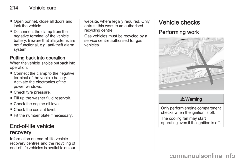
Only perform engine compartment
checks when the ignition is off.
The cooling fan may start
operating even if the ignition is off.
Page 221 of 321
Vehicle care219
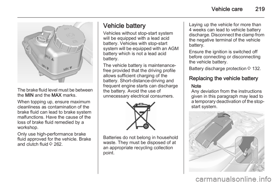
The brake fluid level must be betweenthe MIN and the MAX marks.
When topping up, ensure maximum cleanliness as contamination of the
brake fluid can lead to brake system
malfunctions. Have the cause of the
loss of brake fluid remedied by a
workshop.
Only use high-performance brake
fluid approved for the vehicle. Brake
and clutch fluid 3 262.
Vehicle battery
Vehicles without stop-start system
will be equipped with a lead acid
battery. Vehicles with stop-start
system will be equipped with an AGM battery which is not a lead acid
battery.
The vehicle battery is maintenance-
free provided that the driving profile
allows sufficient charging of the
battery. Short-distance-driving and
frequent engine starts can discharge
the battery. Avoid the use of
unnecessary electrical consumers.
Batteries do not belong in household
waste. They must be disposed of at
an appropriate recycling collection
point.
Laying up the vehicle for more than
4 weeks can lead to vehicle battery
discharge. Disconnect the clamp from the negative terminal of the vehicle
battery.
Ensure the ignition is switched off
before connecting or disconnecting
the vehicle battery.
Battery discharge protection 3 132.
Replacing the vehicle battery Note
Any deviation from the instructions
given in this paragraph may lead to
a temporary deactivation of the stop-
start system.
Page 222 of 321
220Vehicle care
The vehicle battery is covered.
Remove the cover to replace the
battery. Lift up the cover at the rear
and unlatch it at the front.
When the battery is being replaced, please ensure that there are no open ventilation holes in the vicinity of the
positive terminal. If a ventilation hole
is open in this area, it must be closed
off with a dummy cap, and the
ventilation in the vicinity of the
negative terminal must be opened.
Only use vehicle batteries that allow the fuse box to be mounted above the battery.
In vehicles with stop-start system, be
sure to have the AGM (Absorptive
Glass Mat) battery replaced with an
AGM battery again.
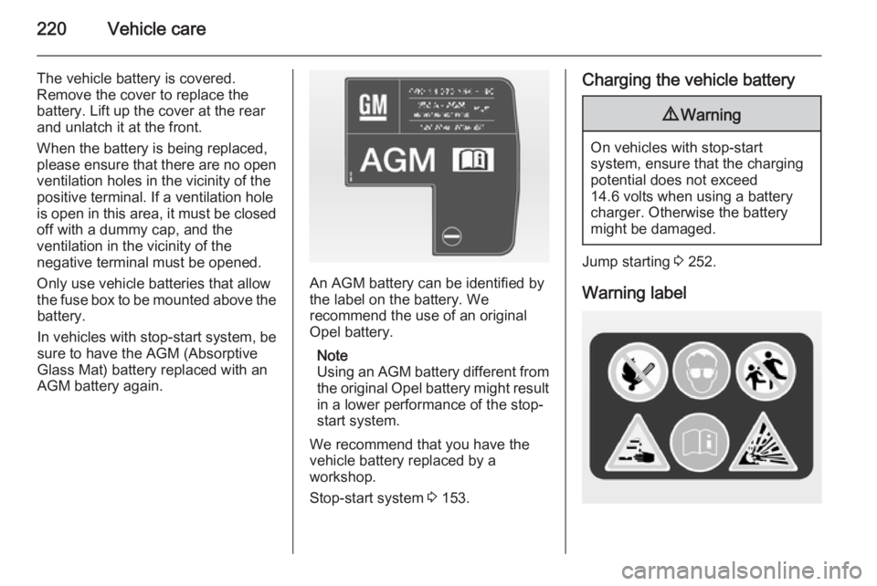
An AGM battery can be identified by
the label on the battery. We
recommend the use of an original
Opel battery.
Note
Using an AGM battery different from
the original Opel battery might result in a lower performance of the stop-
start system.
We recommend that you have the
vehicle battery replaced by a
workshop.
Stop-start system 3 153.
Charging the vehicle battery9 Warning
On vehicles with stop-start
system, ensure that the charging potential does not exceed
14.6 volts when using a battery
charger. Otherwise the battery
might be damaged.
Jump starting 3 252.
Warning label
Page 223 of 321
Vehicle care221
Meaning of symbols:■ No sparks, naked flames or smoking.
■ Always shield eyes. Explosive gases can cause blindness or
injury.
■ Keep the vehicle battery out of reach of children.
■ The vehicle battery contains sulphuric acid which could cause
blindness or serious burn injuries.
■ See the Owner’s Manual for further
information.
■ Explosive gas may be present in the vicinity of the vehicle battery.Diesel fuel system
bleeding
If the tank has been run dry, the diesel fuel system must be bled. Switch on
the ignition three times for
15 seconds at a time. Then crank the
engine for a maximum of
40 seconds. Repeat this process after
no less than 5 seconds. If the engine
fails to start, seek the assistance of a
workshop.
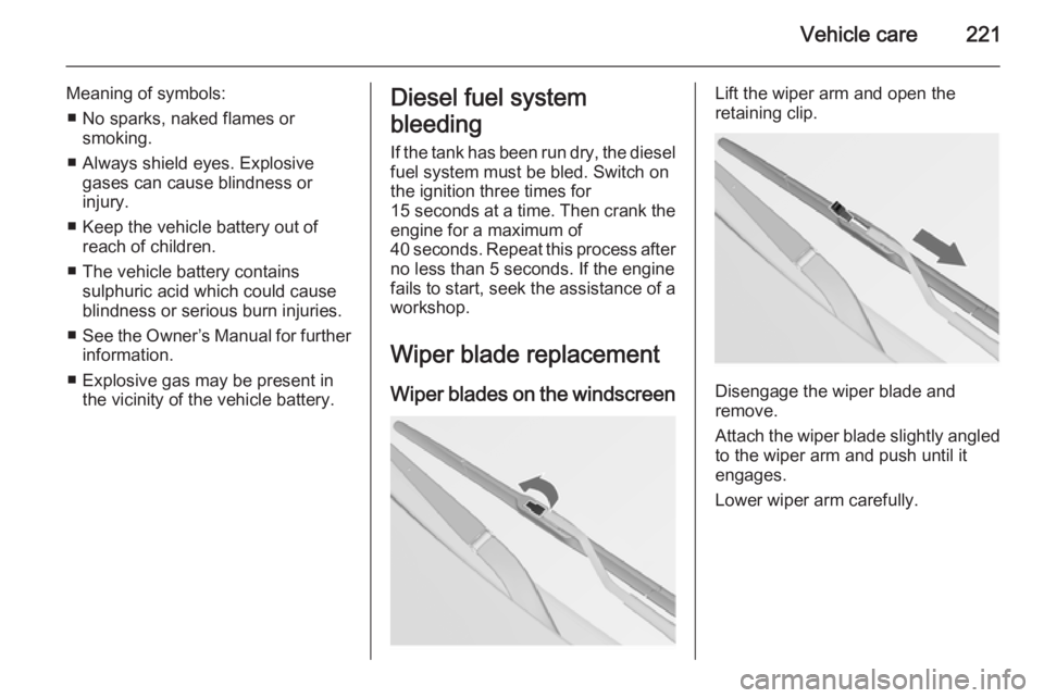
Wiper blade replacement Wiper blades on the windscreenLift the wiper arm and open the
retaining clip.
Disengage the wiper blade and
remove.
Attach the wiper blade slightly angled
to the wiper arm and push until it
engages.
Lower wiper arm carefully.
Page 237 of 321
Vehicle care235
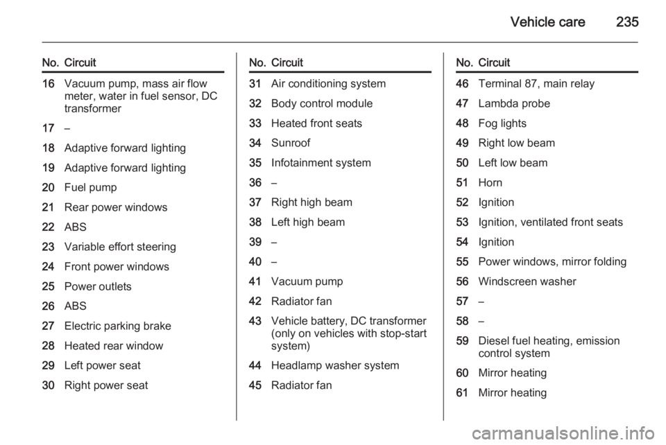
No.Circuit16Vacuum pump, mass air flow
meter, water in fuel sensor, DC
transformer17–18Adaptive forward lighting19Adaptive forward lighting20Fuel pump21Rear power windows22ABS23Variable effort steering24Front power windows25Power outlets26ABS27Electric parking brake28Heated rear window29Left power seat30Right power seatNo.Circuit31Air conditioning system32Body control module33Heated front seats34Sunroof35Infotainment system36–37Right high beam38Left high beam39–40–41Vacuum pump42Radiator fan43Vehicle battery, DC transformer (only on vehicles with stop-start
system)44Headlamp washer system45Radiator fanNo.Circuit46Terminal 87, main relay47Lambda probe48Fog lights49Right low beam50Left low beam51Horn52Ignition53Ignition, ventilated front seats54Ignition55Power windows, mirror folding56Windscreen washer57–58–59Diesel fuel heating, emission
control system60Mirror heating61Mirror heating
Page 238 of 321
236Vehicle care
No.Circuit62–63Rear window sensor64Adaptive forward lighting65Auxiliary pump (only on vehicleswith stop-start system)66Rear window washer system67Fuel system control module68–69Vehicle battery sensor70Rain sensor71Vehicle battery sensor
After changing of defective fuses
close the fuse box cover and press
until it engages.
If the fuse box cover is not closed
correctly, malfunctions may occur.
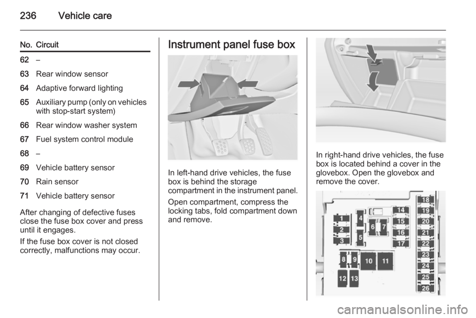
Instrument panel fuse box
In left-hand drive vehicles, the fuse
box is behind the storage
compartment in the instrument panel.
Open compartment, compress the
locking tabs, fold compartment down and remove.
In right-hand drive vehicles, the fuse
box is located behind a cover in the
glovebox. Open the glovebox and
remove the cover.
Page 248 of 321
246Vehicle care
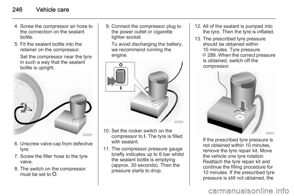
4.Screw the compressor air hose to
the connection on the sealant
bottle.
5. Fit the sealant bottle into the retainer on the compressor.
Set the compressor near the tyre
in such a way that the sealant
bottle is upright.
6. Unscrew valve cap from defective
tyre.
7. Screw the filler hose to the tyre valve.
8. The switch on the compressor must be set to J.
9. Connect the compressor plug to
the power outlet or cigarette
lighter socket.
To avoid discharging the battery,
we recommend running the
engine.
10. Set the rocker switch on the compressor to I. The tyre is filled
with sealant.
11. The compressor pressure gauge briefly indicates up to 6 bar whilstthe sealant bottle is emptying
(approx. 30 seconds). Then the
pressure starts to drop.
12. All of the sealant is pumped into the tyre. Then the tyre is inflated.
13. The prescribed tyre pressure should be obtained within
10 minutes. Tyre pressure
3 289 . When the correct pressure
is obtained, switch off the
compressor.
If the prescribed tyre pressure is
not obtained within 10 minutes,
remove the tyre repair kit. Move
the vehicle one tyre rotation.
Reattach the tyre repair kit and
continue the filling procedure for
10 minutes. If the prescribed tyre
pressure is still not obtained, the
Page 254 of 321
252Vehicle care9Warning
Storing a jack, a wheel or other
equipment in the load
compartment could cause injury if they are not fixed properly. During a sudden stop or a collision, looseequipment could strike someone.
Store wheel, jack and tools always
in the original storage location and secure them by fixing.
Temporary spare wheel
Caution
The use of a spare wheel that issmaller than the other wheels or in
combination with winter tyres
could affect driveability. Have the defective tyre replaced as soon as
possible.
Only mount one temporary spare
wheel. Do not drive faster than
80 km/h. Take curves slowly. Do not use for a long period of time.
If your vehicle gets a flat tyre on the
rear while towing another vehicle,
mount the temporary spare wheel in the front and the full tyre in the rear.
Tyre chains 3 244.
Directional tyres Fit directional tyres such that they roll
in the direction of travel. The rolling
direction is indicated by a symbol
(e.g. an arrow) on the sidewall.
The following applies to tyres fitted
opposing the rolling direction:
■ Driveability may be affected. Have the defective tyre renewed or
repaired as soon as possible.
■ Drive particularly carefully on wet and snow-covered road surfaces.Jump starting
Do not start with quick charger.
A vehicle with a discharged vehicle
battery can be started using jump
leads and the vehicle battery of
another vehicle.9 Warning
Be extremely careful when starting
with jump leads. Any deviation
from the following instructions can
lead to injuries or damage caused
by battery explosion or damage to the electrical systems of both
vehicles.
9 Warning
Avoid contact of the battery with
eyes, skin, fabrics and painted
surfaces. The fluid contains
sulphuric acid which can cause
injuries and damage in the event
of direct contact.