brake light OPEL INSIGNIA 2017 Manual user
[x] Cancel search | Manufacturer: OPEL, Model Year: 2017, Model line: INSIGNIA, Model: OPEL INSIGNIA 2017Pages: 327, PDF Size: 9.3 MB
Page 177 of 327
Driving and operating175Parking brake
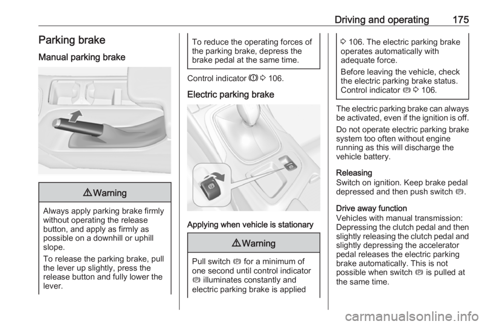
Manual parking brake9 Warning
Always apply parking brake firmly
without operating the release
button, and apply as firmly as
possible on a downhill or uphill
slope.
To release the parking brake, pull
the lever up slightly, press the
release button and fully lower the
lever.
To reduce the operating forces of
the parking brake, depress the
brake pedal at the same time.
Control indicator R 3 106.
Electric parking brake
Applying when vehicle is stationary
9 Warning
Pull switch m for a minimum of
one second until control indicator
m illuminates constantly and
electric parking brake is applied
3 106. The electric parking brake
operates automatically with
adequate force.
Before leaving the vehicle, check
the electric parking brake status.
Control indicator m 3 106.
The electric parking brake can always
be activated, even if the ignition is off.
Do not operate electric parking brake
system too often without engine
running as this will discharge the vehicle battery.
Releasing
Switch on ignition. Keep brake pedal
depressed and then push switch m.
Drive away function Vehicles with manual transmission:
Depressing the clutch pedal and then
slightly releasing the clutch pedal and slightly depressing the accelerator
pedal releases the electric parking
brake automatically. This is not
possible when switch m is pulled at
the same time.
Page 187 of 327

Driving and operating185It then adjusts the vehicle speed to
follow the vehicle ahead at the
selected following distance. The
vehicle speed increases or decreases
to follow the vehicle in front, but will
not exceed the set speed. It may
apply limited braking with activated
brake lights.
The adaptive cruise control can store and maintain speeds over approx.
25 km/h. If following a vehicle ahead
driving slower than 25 km/h, the
slower speed will be set. On vehicles
with automatic transmission, the
system can also brake to a stop.
Adaptive cruise control uses a radar
sensor to detect vehicles ahead. If no
vehicle is detected in the driving path, the adaptive cruise control will
behave like a traditional cruise
control.
For safety reasons, the system
cannot be activated before the brake
pedal or clutch pedal has been
depressed once after switching on
ignition.
Adaptive cruise control is mainly
advised to be used on long straight
roads like highways or country roads
with steady traffic. Do not use the
system if it is not advisable to
maintain a constant speed.
Control indicator A 3 110, m 3 110,
C 3 110.9 Warning
The complete driver attention is
always required while driving with adaptive cruise control. The driver stays fully in control of the vehicle
because the brake pedal, the
accelerator pedal and the cancel
switch have priority over any
adaptive cruise control operation.
Switching on
Press C to switch on adaptive cruise
control. The control indicator m in the
instrument cluster illuminates white.
Additionally C appears in the Driver
Information Centre.
Activation by setting the speed
Adaptive cruise control can be
activated between 25 km/h and
180 km/h.
Accelerate to the desired speed and
turn thumb wheel to SET/-, the
current speed is stored and
maintained. Control indicator m in the
instrument cluster illuminates green.
Page 192 of 327
190Driving and operating● Adaptive cruise control does notbrake for pedestrians, animals,very slow speed driving or
stopped vehicles.
● Do not use adaptive cruise control when towing a trailer.
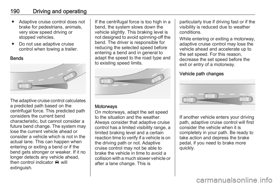
Bends
The adaptive cruise control calculates
a predicted path based on the
centrifugal force. This predicted path
considers the current bend
characteristic, but cannot consider a
future bend change. The system may lose the current vehicle ahead or
consider a vehicle which is not in the
actual lane. This can happen when
entering or exiting a bend or if the
bend gets stronger or weaker. If it no
longer detects any vehicle ahead,
then control indicator A will
extinguish.
If the centrifugal force is too high in a bend, the system slows down the vehicle slightly. This braking level is
not designed to avoid spinning-off the
bend. The driver is responsible for
reducing the selected speed before
entering a bend and in general to
adapt the speed to the road type and
to existing speed limits.
Motorways
On motorways, adapt the set speed
to the situation and the weather.
Always consider that adaptive cruise
control has a limited visibility range, a
limited braking level and a certain
reaction time to verify if a vehicle is on
the driving path or not. Adaptive
cruise control may not be able to
brake the vehicle in time to avoid a
collision with a much slower vehicle or after a lane change. This is
particularly true if driving fast or if the
visibility is reduced due to weather
conditions.
While entering or exiting a motorway,
adaptive cruise control may lose the
vehicle ahead and accelerate up to
the set speed. For this reason,
decrease the set speed before the
exit or entry of a motorway.
Vehicle path changes
If another vehicle enters your driving
path, adaptive cruise control will first
consider the vehicle when it is
completely in your path. Be ready to
take action and depress the brake
pedal, if you need to brake more
quickly.
Page 195 of 327

Driving and operating193
Press E, the current setting is shown
in the Driver Information Centre.
Press E again to change the alert
sensitivity. The setting is also displayed in the Driver Information
Centre.Note that the alert timing sensitivity
setting is shared with the following
distance setting of the adaptive cruise control 3 184. So changing the alert
timing sensitivity changes the
adaptive cruise control following
distance setting.
Alerting the driver
The vehicle ahead control indicator A illuminates green in the instrument
cluster when the system has detected
a vehicle in the driving path.
The control indicator A changes to
yellow when the distance to a
preceding moving vehicle gets too
short or when approaching another
vehicle too rapidly.Caution
The colour lighting of this control
indicator does not correspond to
local traffic laws on following
distance. The driver bears full
responsibility for maintaining safe
following distance according to
applicable traffic rules, weather
and road conditions etc. at all
times.
If a collision is imminent, the collision
alert symbol pops-up in the Driver
Information Centre and a warning
chime sounds. Depress the brake
pedal if it is required by the situation.
Page 198 of 327

196Driving and operatingActive emergency braking
Active emergency braking can help to reduce the damage from crashes with vehicles and obstacles directly
ahead, when a collision can no longer be avoided either by manual braking
or by steering. Before the active
emergency braking applies, the driver
is warned by the forward collision
alert 3 192.
The feature uses various inputs (e.g.
radar sensor, brake pressure, vehicle speed) to calculate the probability of
a frontal collision.
Active emergency braking operates
automatically above walking speed,
provided that Auto Collision
Preparation setting is not deactivated
in the vehicle personalisation menu
3 121.
The system includes: ● brake preparation system
● emergency automatic braking
● forward looking brake assist9Warning
This system is not intended to
replace the driver responsibility for driving the vehicle and looking
ahead. Its function is limited to
supplemental use only. The driver must continue to apply the brake
pedal as the driving situation
dictates.
Brake preparation system
When approaching a vehicle ahead
so quickly that a collision is likely, the
brake preparation system slightly
pressurises the brakes. This reduces
the response time, when a manual or automatic braking is requested.
The brake system is prepared so that braking can occur more rapidly.
Emergency automatic braking
After the brake preparation and just
before the imminent collision, this
function automatically applies limited
braking to reduce the impact speed of the collision.
Below a speed of 18 km/h the system
can apply full braking.
Forward looking brake assist In addition to the brake preparation
system and emergency automatic
braking, the forward looking brake
assist function makes the brake assist
more sensitive. Therefore,
depressing the brake pedal less
strongly results in immediate hard
braking. This function helps the driver brake quicker and harder before the
imminent collision.9 Warning
Active emergency braking is not
designed to apply hard
autonomous braking or to
automatically avoid a collision. It is designed to reduce the vehicle
speed before a collision. It may not
react for stopped vehicles,
pedestrians or animals. After a
Page 215 of 327

Driving and operating213Fault
The traffic sign assistant system may
not operate correctly if:
● The area of the windscreen, where the front camera is
located, is not clean or affected
by foreign items, e.g. stickers.
● Traffic signs are completely or partially covered or difficult to
discern.
● There are adverse environmental
conditions, e.g. heavy rain, snow,
direct sunlight or shadows.
● Traffic signs are incorrectly mounted or damaged.
● Traffic signs do not comply with the Vienna Convention on traffic
signs (Wiener Übereinkommen
über Straßenverkehrszeichen).Caution
The system is intended to help the driver within a defined speed
range to recognise certain traffic
signs. Do not ignore traffic signs
which are not displayed by the
system.
The system does not recognise
any other than the conventional
traffic signs that might give or end
a speed limit.
Do not let this special feature
tempt you into taking risks when
driving.
Always adapt speed to the road
conditions.
The driver assistance systems do not relieve the driver from full
responsibility for vehicle
operation.
Lane departure warning
The lane departure warning system
observes the lane markings between
which the vehicle is driving, via a front camera. The system detects lane
changes and warns the driver in the
event of an unintended lane change
by visual and acoustic signals.
Criteria for the detection of an
unintended lane change are:
● No operation of turn signals.
● No brake pedal operation.
● No active accelerator operation or speeding-up.
● No active steering.
If the driver is active, no warning will
be issued.
Activation
The lane departure warning system isactivated by pressing ). The
illuminated LED in the button
indicates that the system is switched
Page 224 of 327
222Driving and operatingFuel consumption data and CO2
emission data are determined
according to regulation R (EC) No.
715/2007 (in the version respectively
applicable), taking into consideration
the vehicle weight in running order, as specified by the regulation.
The figures are provided only for the
purpose of comparison between
different vehicle variants and must not be taken as a guarantee for the
actual fuel consumption of a
particular vehicle. Additional
equipment may result in slightly
higher results than the stated
consumption and CO 2 figures.
Furthermore, fuel consumption is
dependent on personal driving style
as well as road and traffic conditions.Trailer hitch
General information
The factory-fitted towing equipment is
folded up under the rear bumper
fascia.
Entrust retrofitting of towing
equipment to a workshop. It may be
necessary to make changes that
affect the cooling system, heat
shields or other equipment. Only use
towing equipment that has been
approved for your vehicle.
To avoid vehicle damage, the power
tailgate cannot be operated with the
radio remote control when a trailer is
electrically connected.
The bulb outage detection function for trailer brake light cannot detect a
partial bulb outage, e.g. in case of four
times five watt bulbs, the function only detects lamp outage when only a
single five Watt lamp remains or none
remain.
Fitting of towing equipment could
cover the opening of the towing eye.
If this is the case use the coupling ball bar for towing.Driving characteristics and
towing tips
Before attaching a trailer, lubricate the coupling ball. However, do not do
so if a stabiliser, which acts on the
coupling ball, is being used to reduce snaking movements.
For trailers with low driving stability
and trailers with a permitted gross
vehicle weight of more than 1400 kg (Front-wheel drive)/1600 kg (All-
wheel drive) the use of a stabiliser is
strongly recommended when driving
above 80 km/h.
If the trailer starts snaking, drive more
slowly, do not attempt to correct the
steering and brake sharply if
necessary.
When driving downhill, drive in the
same gear as if driving uphill and
drive at a similar speed.
Adjust tyre pressure to the value
specified for full load 3 295.
Page 228 of 327
226Vehicle careVehicle careGeneral Information...................227
Accessories and vehicle modifications .......................... 227
Vehicle storage ........................227
End-of-life vehicle recovery .....228
Vehicle checks ........................... 228
Performing work ......................228
Bonnet ..................................... 228
Engine oil ................................. 229
Automatic transmission fluid ....230
Engine coolant ......................... 231
Power steering fluid .................232
Washer fluid ............................ 232
Brakes ..................................... 233
Brake fluid ............................... 233
Vehicle battery ......................... 233
Diesel fuel system bleeding .....235
Wiper blade replacement ........235
Bulb replacement .......................236
Halogen headlights ..................237
Xenon headlights .....................239
Fog lights ................................. 241
Tail lights ................................. 242
Side turn signal lights ..............244
Number plate light ...................245Interior lights ............................ 246
Instrument panel illumination ...246
Electrical system ........................246
Fuses ....................................... 246
Engine compartment fuse box . 248
Instrument panel fuse box .......250
Load compartment fuse box ....251
Vehicle tools .............................. 253
Tools ........................................ 253
Wheels and tyres .......................254
Winter tyres ............................. 254
Tyre designations ....................254
Tyre pressure .......................... 254
Tyre pressure monitoring system .................................... 256
Tread depth ............................. 257
Changing tyre and wheel size . 258
Wheel covers ........................... 258
Tyre chains .............................. 259
Tyre repair kit .......................... 259
Wheel changing .......................262
Spare wheel ............................ 264
Jump starting ............................. 267
Towing ....................................... 268
Towing the vehicle ...................268
Towing another vehicle ...........270Appearance care .......................272
Exterior care ............................ 272
Interior care ............................. 274
Page 244 of 327
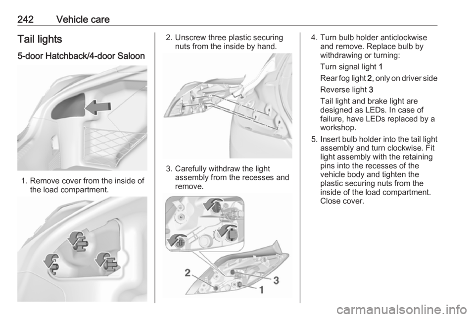
242Vehicle careTail lights5-door Hatchback/4-door Saloon
1. Remove cover from the inside of the load compartment.
2. Unscrew three plastic securingnuts from the inside by hand.
3. Carefully withdraw the lightassembly from the recesses and
remove.
4. Turn bulb holder anticlockwise and remove. Replace bulb by
withdrawing or turning:
Turn signal light 1
Rear fog light 2, only on driver side
Reverse light 3
Tail light and brake light are
designed as LEDs. In case of
failure, have LEDs replaced by a
workshop.
5. Insert bulb holder into the tail light
assembly and turn clockwise. Fit
light assembly with the retaining
pins into the recesses of the
vehicle body and tighten the
plastic securing nuts from the
inside of the load compartment.
Close cover.
Page 245 of 327
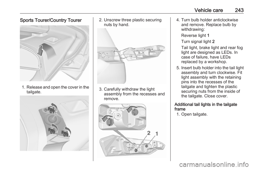
Vehicle care243Sports Tourer/Country Tourer
1.Release and open the cover in the
tailgate.
2. Unscrew three plastic securing nuts by hand.
3. Carefully withdraw the lightassembly from the recesses and
remove.
4. Turn bulb holder anticlockwise and remove. Replace bulb by
withdrawing:
Reverse light 1
Turn signal light 2
Tail light, brake light and rear fog
light are designed as LEDs. In
case of failure, have LEDs
replaced by a workshop.
5. Insert bulb holder into the tail light
assembly and turn clockwise. Fit
light assembly with the retaining
pins into the recesses of the
tailgate and tighten the plastic
securing nuts from the inside of
the tailgate. Close cover.
Additional tail lights in the tailgate
frame
1. Open tailgate.