ECU OPEL INSIGNIA BREAK 2017.5 Manual user
[x] Cancel search | Manufacturer: OPEL, Model Year: 2017.5, Model line: INSIGNIA BREAK, Model: OPEL INSIGNIA BREAK 2017.5Pages: 303, PDF Size: 8.46 MB
Page 77 of 303

Storage75First aid kit
Stow the first aid kit on the right side
of the load compartment and secure it with the strap.
Roof rack system
Roof rack
For safety reasons and to avoid damage to the roof, the vehicle
approved roof rack system is
recommended. For further
information, contact your workshop.
Mounting roof rack
Open all doors.
Mounting points are located in each
door frame of the vehicle body.
Fasten the roof rack according to the installation instructions delivered with the roof rack.
Remove the roof rack when not inuse.
Page 78 of 303

76StorageLoading information
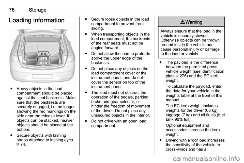
● Heavy objects in the loadcompartment should be placed
against the seat backrests. Make
sure that the backrests are
securely engaged, i.e. no longer
showing the red markings on the side near the release lever. If
objects can be stacked, heavier
objects should be placed at the
bottom.
● Secure objects with lashing straps attached to lashing eyes
3 74.
● Secure loose objects in the load
compartment to prevent from
sliding.
● When transporting objects in the load compartment, the backrestsof the rear seats must not be
angled forward.
● Do not allow the load to protrude above the upper edge of the
backrests.
● Do not place any objects on the load compartment cover or theinstrument panel, and do not
cover the sensor on top of the instrument panel.
● The load must not obstruct the operation of the pedals, parking
brake and gear selector, or
hinder the freedom of movement of the driver. Do not place any
unsecured objects in the interior.
● Do not drive with an open load compartment.9Warning
Always ensure that the load in the
vehicle is securely stowed.
Otherwise objects can be thrown
around inside the vehicle and
cause personal injury or damage
to the load or vehicle.
● The payload is the difference between the permitted grossvehicle weight (see identification
plate 3 275) and the EC kerb
weight.
To calculate the payload, enter the data for your vehicle in the
weights table at the front of this
manual.
The EC kerb weight includes
weights for the driver (68 kg),
luggage (7 kg) and all fluids (fuel
tank 90% full).
Optional equipment and
accessories increase the kerb
weight.
● Driving with a roof load increases
the sensitivity of the vehicle to
cross-winds and has a
Page 79 of 303

Storage77detrimental effect on vehicle
handling due to the vehicle's
higher centre of gravity.
Distribute the load evenly and
secure it properly with retaining
straps. Adjust the tyre pressure
and vehicle speed according to
the load conditions. Check and
retighten the straps frequently.
Do not drive faster than 120 km/ h.
The permissible roof load is
100 kg. The roof load is the
combined weight of the roof rack
and the load.
Page 127 of 303

Instruments and controls125If the OnStar service is used on
another vehicle, press Z and request
that the account be transferred to the new vehicle.
Note
In any case, if the vehicle is disposed
of, sold or otherwise transferred,
immediately inform OnStar about
the changes and terminate the
OnStar service on this vehicle.
Vehicle location
The vehicle location is transmitted to OnStar when service is requested or triggered. A message on the Info-
Display informs about this
transmission.
To activate or deactivate the
transmission of the vehicle location,
press and hold j until an audio
message is heard.
The deactivation is indicated by the
status light flashing red and green for a short period of time and each time
the vehicle is started.
Note
If the transmission of the vehicle
location is deactivated, some
services are no longer available.Note
The vehicle location always remains
accessible to OnStar in the case of
an emergency.
Find the privacy policy in your
account.
Software updates
OnStar may remotely carry out software updates without further notice or consent. These updates are
to enhance or maintain safety and
security or the operation of the
vehicle.
These updates may concern privacy
issues. Find the privacy policy in your account.
Page 169 of 303

Driving and operating167Steering wheel paddles
Move selector lever out of position D
towards the left in position M.
Manual mode M can be activated
from position D in each driving
situation and speed.
Pull steering wheel paddles to select
gears manually.
Pull right paddle + to shift to a higher
gear.
Pull left paddle - to shift to a lower
gear.
Multiple pulls allow gears to be
skipped.
The selected gear is indicated in the
instrument cluster.
Temporary manual mode in drive
mode D
Manual paddle shifting is also
possible in automatic mode D. Upon
completion of manual shifting
operation, transmission changes to
automatic mode D after a defined
time.
To interrupt manual mode and return
to D, do one of the following:
● Press + paddle for 1 second.
● Move selector lever towards the left to manual mode and back to
position D.
If the vehicle is at a standstill and
engine is idling, the transmission will
remain in temporary manual mode. It
changes to automatic mode when
accelerator pedal is operated for a
defined time, and no paddle shifting
at the steering wheel is performed.
General
If a higher gear is selected when
vehicle speed is too low, or a lower
gear when vehicle speed is too high,the shift is not executed. This can
cause a message in the Driver
Information Centre.
In manual mode, no automatic
shifting to a higher gear takes place
at high engine revolutions, except
activating the kickdown function.
Gear shift indication
The symbol R or S with a number
beside it is indicated when gear
shifting is recommended for fuel
saving reasons.
Shift indication appears only in
manual mode.
Electronic driving programmes ● Following a cold start, the operating temperature
programme increases engine
speed to quickly bring the
catalytic converter to the required
temperature.
● When SPORT mode is engaged,
the vehicle shifts at higher engine
speeds (unless cruise control is
on). SPORT mode 3 175.
Page 243 of 303

Vehicle care241Lamp assembly in the body
1. Remove the cover on therespective side.
2. Unscrew the two plastic securing nuts from the inside by hand.
3. Carefully withdraw tail lampassembly from recess and
remove.
4. Turn the bulb carrier anticlockwise and remove it from
the lamp assembly.
5. Remove and replace the turn signal light bulb.
6. Attach the bulb carrier to the lamp
assembly.
7. Attach the lamp assembly to the vehicle body and tighten the
securing nuts from the inside of the load compartment. Attach
cover.
Page 244 of 303

242Vehicle careLamp assembly in the tailgate
1. Release the cover in the tailgateand remove it.
2. Unscrew the plastic securing nutby hand.
3. Carefully withdraw the lampassembly from the recesses and
remove.
4. Turn the bulb carrier anticlockwise and remove it from
the lamp assembly.
Rear fog light ( 1)
Reverse light ( 2)
5. Remove and replace the bulb:
Rear fog light
Page 252 of 303

250Vehicle careVehicles with audio speaker
system
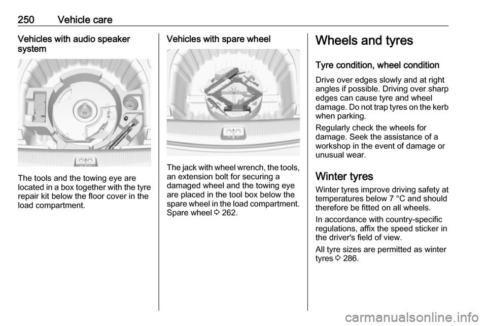
The tools and the towing eye are
located in a box together with the tyre
repair kit below the floor cover in the
load compartment.
Vehicles with spare wheel
The jack with wheel wrench, the tools,
an extension bolt for securing a
damaged wheel and the towing eye
are placed in the tool box below the
spare wheel in the load compartment. Spare wheel 3 262.
Wheels and tyres
Tyre condition, wheel condition Drive over edges slowly and at right
angles if possible. Driving over sharp
edges can cause tyre and wheel
damage. Do not trap tyres on the kerb when parking.
Regularly check the wheels for
damage. Seek the assistance of a
workshop in the event of damage or
unusual wear.
Winter tyres
Winter tyres improve driving safety at temperatures below 7 °C and should
therefore be fitted on all wheels.
In accordance with country-specific
regulations, affix the speed sticker in
the driver's field of view.
All tyre sizes are permitted as winter
tyres 3 286.
Page 263 of 303

Vehicle care2611. Disengage wheel nut caps with ascrewdriver and remove.
Steel wheels with cover: Pull off
the wheel cover.
Alloy wheels: Disengage wheel
nut caps with a screwdriver and
remove. To protect the wheel,
place a soft cloth between the
screwdriver and the alloy wheel.
2. Fold out the wheel wrench and install ensuring that it locates
securely and loosen each wheel
nut by half a turn.
The wheels might be protected by
locking wheel nuts. To loosen
these specific nuts, first attach the
adapter for the locking wheel nuts
onto the head of the nut before
installing the wheel wrench. The
adapter is located in the glovebox.
3. Ensure the jack is correctly positioned under the relevant
vehicle jacking point.
4. Set the jack to the necessary height. Position it directly below
the jacking point in a manner that
prevents it from slipping.
Page 264 of 303

262Vehicle careAttach wheel wrench and with the
jack correctly aligned rotate wheel wrench until wheel is clear of the
ground.
5. Unscrew the wheel nuts. 6. Change the wheel. Spare wheel 3 262.
7. Screw on the wheel nuts.
8. Lower vehicle.
9. Install the wheel wrench ensuring that it locates securely and tighten
each nut in a crosswise
sequence. Tightening torque is
125 Nm.
10. Align the valve hole in the wheel cover with the tyre valve before
installing.
Install wheel nut caps.
11. Install vehicle jacking point cover.
12. Stow and secure the replaced wheel 3 262, the vehicle tools
3 249 and the adapter for the
locking wheel nuts 3 68.
13. Check the tyre pressure of the installed tyre and the wheel nut
torque as soon as possible.Have the defective tyre renewed or
repaired as soon as possible.
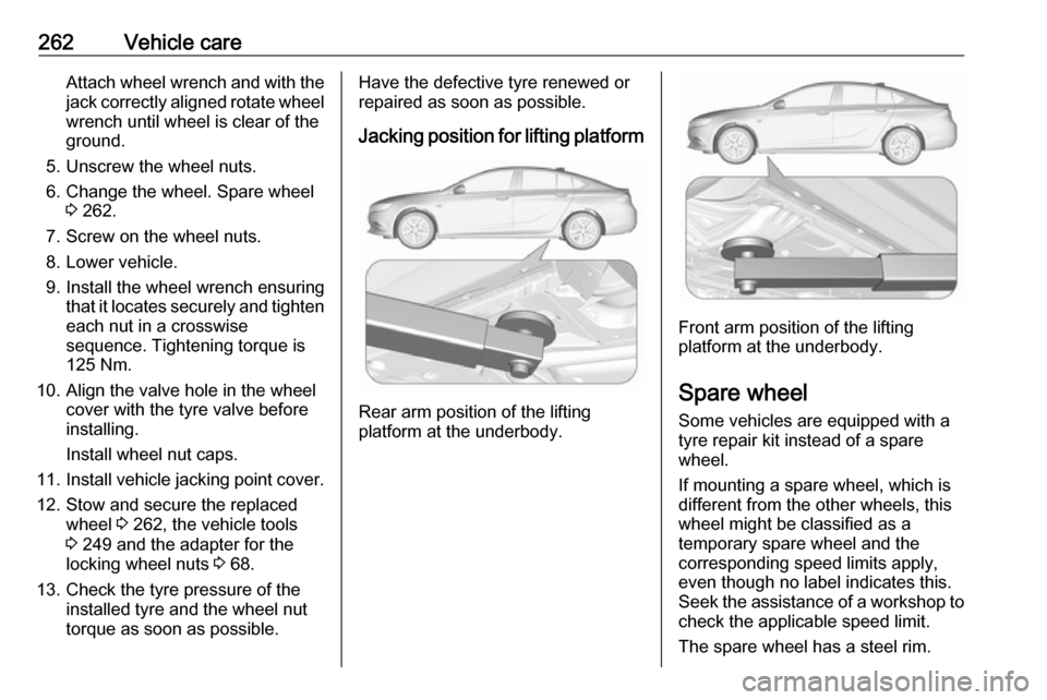
Jacking position for lifting platform
Rear arm position of the lifting
platform at the underbody.
Front arm position of the lifting
platform at the underbody.
Spare wheel Some vehicles are equipped with a
tyre repair kit instead of a spare
wheel.
If mounting a spare wheel, which is
different from the other wheels, this
wheel might be classified as a
temporary spare wheel and the
corresponding speed limits apply,
even though no label indicates this.
Seek the assistance of a workshop to
check the applicable speed limit.
The spare wheel has a steel rim.