window OPEL INSIGNIA BREAK 2020 Manual user
[x] Cancel search | Manufacturer: OPEL, Model Year: 2020, Model line: INSIGNIA BREAK, Model: OPEL INSIGNIA BREAK 2020Pages: 315, PDF Size: 9.45 MB
Page 160 of 315
158Driving and operatingIndication
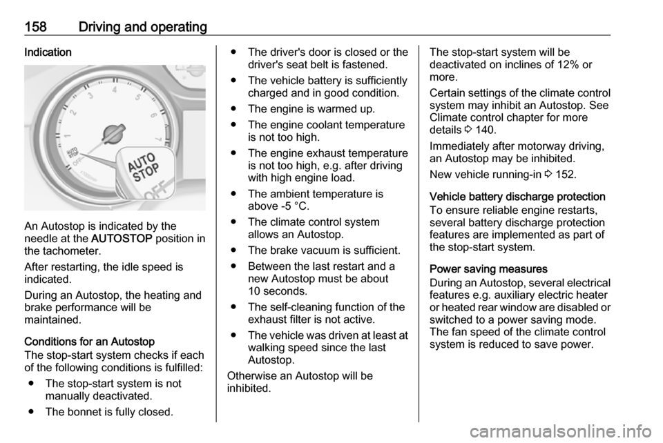
An Autostop is indicated by the
needle at the AUTOSTOP position in
the tachometer.
After restarting, the idle speed is
indicated.
During an Autostop, the heating and
brake performance will be
maintained.
Conditions for an Autostop
The stop-start system checks if each
of the following conditions is fulfilled:
● The stop-start system is not manually deactivated.
● The bonnet is fully closed.
● The driver's door is closed or the driver's seat belt is fastened.
● The vehicle battery is sufficiently charged and in good condition.
● The engine is warmed up.
● The engine coolant temperature is not too high.
● The engine exhaust temperature is not too high, e.g. after driving
with high engine load.
● The ambient temperature is above -5 °C.
● The climate control system allows an Autostop.
● The brake vacuum is sufficient.
● Between the last restart and a new Autostop must be about10 seconds.
● The self-cleaning function of the exhaust filter is not active.
● The vehicle was driven at least at
walking speed since the last
Autostop.
Otherwise an Autostop will be
inhibited.The stop-start system will be
deactivated on inclines of 12% or
more.
Certain settings of the climate control
system may inhibit an Autostop. See
Climate control chapter for more
details 3 140.
Immediately after motorway driving,
an Autostop may be inhibited.
New vehicle running-in 3 152.
Vehicle battery discharge protection
To ensure reliable engine restarts,
several battery discharge protection
features are implemented as part of
the stop-start system.
Power saving measures
During an Autostop, several electrical
features e.g. auxiliary electric heater
or heated rear window are disabled or switched to a power saving mode.
The fan speed of the climate control
system is reduced to save power.
Page 162 of 315
160Driving and operating● If the vehicle is on a levelsurface or uphill slope, engage
first gear or set the selector
lever to position P before
removing the ignition key or
switching off ignition on
vehicles with power button. On an uphill slope, turn the front
wheels away from the kerb.
If the vehicle is on a downhill
slope, engage reverse gear or
set the selector lever to position
P before removing the ignition
key or switching off ignition on
vehicles with power button.
Turn the front wheels towards
the kerb.
● Close the windows and the sunroof.
● Remove the ignition key from the ignition switch or switch off
ignition on vehicles with power
button. Turn the steering wheel until the steering wheel lock is
felt to engage.
For vehicles with automatic
transmission, the key can onlybe removed when the selector
lever is in position P.
● Lock the vehicle by pressing the
button on the door handle or the
button e on the remote control.
● Activate the anti-theft alarm system.
● The engine cooling fans may run
after the engine has been
switched off 3 231.
Caution
After running at high engine
speeds or with high engine loads,
operate the engine briefly at a low load or run in neutral for
approx. 30 seconds before
switching off, in order to protect
the turbocharger.
Note
In the event of an accident with
airbag deployment, the engine is
turned off automatically if the vehicle
comes to a standstill within a certain time.
Engine exhaust9 Danger
Engine exhaust gases contain
poisonous carbon monoxide,
which is colourless and odourless and could be fatal if inhaled.
If exhaust gases enter the interior
of the vehicle, open the windows.
Have the cause of the fault
rectified by a workshop.
Avoid driving with an open load
compartment, otherwise exhaust
gases could enter the vehicle.
Exhaust filter
The exhaust filter is a particle filter for diesel and petrol engines.
Page 163 of 315
Driving and operating161Automatic cleaning processThe exhaust filter system filters soot
particles out of the exhaust gases.
The system includes a self-cleaning
function that runs automatically
during driving without any notification.
The filter is cleaned by periodically
burning off the soot particles at high
temperature. This process takes
place automatically under set driving
conditions and may take up to
25 minutes. Typically it needs
between 7 and 12 minutes. Autostop
is not available and fuel consumption may be higher during this period. The
emission of smells and smoke during
this process is normal.
System requires cleaning Under certain conditions, e.g. driving
short distances, the system cannot
clean itself automatically.
If cleaning of the filter is required and if previous driving conditions did not
enable automatic cleaning, it will be
indicated by a warning message in
the Driver Information Centre.A warning message appears when
exhaust filter is full. Start cleaning
process as soon as possible.
A warning message also appears
when exhaust filter has reached the
maximum filling level. Start cleaning
process immediately to avoid
damage to the engine.
Activate self-cleaning process
Cleaning process is completed more
quickly at high engine speeds and loads. Therefore, drive in lower gears
than normal, and use manual gear
selection on vehicles with automatic
transmission. Usage of electrical
consumers like air conditioning and
heated windows to increase engine
load supports cleaning process.Caution
If possible, do not interrupt
cleaning process. Drive until
cleaning is completed to avoid the
need for service or repair by a
workshop.
Vehicles with petrol engine
To activate cleaning process,
continue driving, keep engine speed
above 2500 rpm. Shift down if
necessary.
Drive dynamically at different engine
speeds. Use engine brake for
deceleration, if possible.
Keep on driving until self-cleaning
operation is complete and the display
message disappears.Vehicles with diesel engine
To activate cleaning process,
continue driving, keep engine speed
above 2000 rpm, ideally and
continuously around 2500 rpm. Shift
down if necessary.
Keep on driving until self-cleaning
operation is complete and the display message disappears.
Page 232 of 315

230Vehicle careCaution
When transporting the vehicle on
a train or on a recovery vehicle, the
mud flaps might be damaged.
Vehicle storage
Storage for a long period of time
If the vehicle is to be stored for several months:
● Wash and wax the vehicle.
● Have the wax in the engine compartment and underbody
checked.
● Clean and preserve the rubber seals.
● Fill up fuel tank completely.
● Change the engine oil.
● Drain the washer fluid reservoir.
● Check the coolant antifreeze and
corrosion protection.
● Adjust tyre pressure to the value specified for full load.
● Park the vehicle in a dry, wellventilated place. Engage first or
reverse gear or set selector lever
to P. Prevent the vehicle from
rolling.
● Do not apply the parking brake.
● Open the bonnet, close all doors and lock the vehicle.
● Disconnect the clamp from the negative terminal of the vehicle
battery. Note that all systems are
not functional, e.g. anti-theft
alarm system.
Putting back into operation
When the vehicle is to be put back into operation:
● Connect the clamp to the negative terminal of the vehicle
battery. Initialize the power
windows 3 41.
● Check tyre pressure.
● Fill up the washer fluid reservoir.
● Check the engine oil level.
● Check the coolant level.
● Fit the number plate if necessary.End-of-life vehicle recovery
Information on end-of-life vehicle
recovery centres and the recycling of
end-of-life vehicles is available on our website, where legally required. Only
entrust this work to an authorised
recycling centre.
Page 238 of 315
236Vehicle careReplacing the vehicle batteryNote
Any deviation from the instructions
given in this section may lead to
temporary deactivation or
disturbance of the stop-start system.
When the vehicle battery is being
replaced, please ensure that there
are no open ventilation holes in the
vicinity of the positive terminal. If a
ventilation hole is open in this area, it
must be closed off with a dummy cap, and the ventilation in the vicinity of the negative terminal must be opened.
Ensure that the battery is always
replaced by the same type of battery.
We recommend that you have the
vehicle battery replaced by a
workshop.
Stop-start system 3 157.Charging the vehicle battery9 Warning
On vehicles with stop-start
system, ensure that the charging potential does not exceed 14.6 V
when using a battery charger.
Otherwise the vehicle battery may be damaged.
Jump starting 3 269.
Discharge protection Battery voltage
When the vehicle battery voltage is
running low, a warning message will
appear in the Driver Information
Centre.
1. Switch off any electrical consumers which are not requiredfor a safe ride, e.g. seat heating,
heated rear window or other main consumers.
2. Charge the vehicle battery by driving continuously for a while or
by using a charging device.
The warning message will disappear
after the engine has been started
twice without a voltage drop.
If the vehicle battery cannot be
recharged, have the cause of the fault
remedied by a workshop.
Vehicle battery state of charge
function
The function guarantees longest vehicle battery life via a generator
with controllable power output and
optimised power distribution.
To prevent discharge of the vehicle
battery when driving, the following
systems are reduced automatically in two stages and finally switched off:
● auxiliary heater
● heated rear and front window
● heated steering wheel
● heated mirrors
● heated seats
● fan
In the second stage, a message
which confirms the activation of the
vehicle battery discharge protection
will be displayed in the Driver
Information Centre.
Page 240 of 315
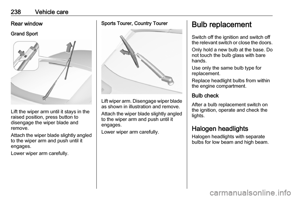
238Vehicle careRear windowGrand Sport
Lift the wiper arm until it stays in the
raised position, press button to
disengage the wiper blade and
remove.
Attach the wiper blade slightly angled
to the wiper arm and push until it
engages.
Lower wiper arm carefully.
Sports Tourer, Country Tourer
Lift wiper arm. Disengage wiper blade as shown in illustration and remove.
Attach the wiper blade slightly angled
to the wiper arm and push until it
engages.
Lower wiper arm carefully.
Bulb replacement
Switch off the ignition and switch off
the relevant switch or close the doors.
Only hold a new bulb at the base. Do not touch the bulb glass with bare
hands.
Use only the same bulb type for
replacement.
Replace headlight bulbs from within
the engine compartment.
Bulb check
After a bulb replacement switch on
the ignition, operate and check the
lights.
Halogen headlights Halogen headlights with separate
bulbs for low beam and high beam.
Page 252 of 315

250Vehicle careNo.Circuit1–2–3ABS4–5–6Tailgate7Rear fog light / Front fog lights8Memory module9Heated windscreen10Seat lumbar11DC / DC battery12Heated rear window13Heated mirror14–15–16Front wiper17Power seat, passengerNo.Circuit18Sunblind19Power seat, driver20–21Sunroof22Rear wiper / Airbag23Adaptive forward lighting24–25–26Transmission control module27Ignition / Instrument panel28–29Rear view camera / Air vent30Malfunction indicator light /
Trailer31–32Camera33Seat heat front34Seat heat rearNo.Circuit35Damping / All-wheel drive36Fuel system37–38–39–40Steering wheel lock41–42–43Heated steering wheel44Headlight range adjustment45–46Engine control module47–48DC/DC converter / Air vent / E-
Boost49Rear door control module50–51–
Page 254 of 315
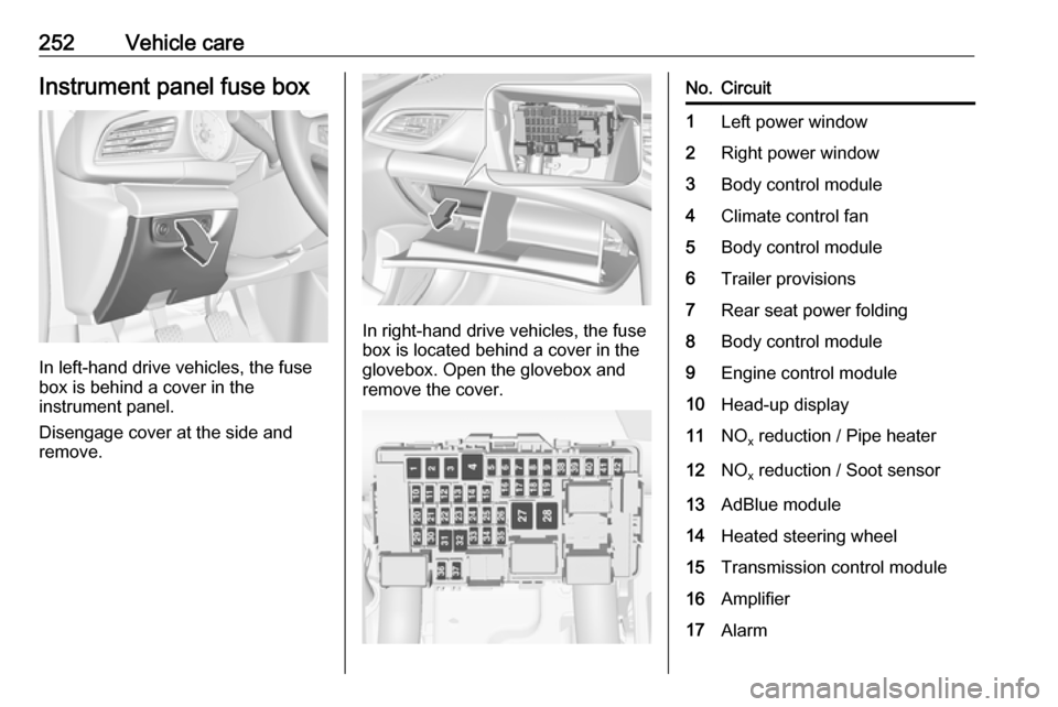
252Vehicle careInstrument panel fuse box
In left-hand drive vehicles, the fuse
box is behind a cover in the
instrument panel.
Disengage cover at the side and
remove.
In right-hand drive vehicles, the fuse
box is located behind a cover in the
glovebox. Open the glovebox and
remove the cover.
No.Circuit1Left power window2Right power window3Body control module4Climate control fan5Body control module6Trailer provisions7Rear seat power folding8Body control module9Engine control module10Head-up display11NO x reduction / Pipe heater12NO
x reduction / Soot sensor13AdBlue module14Heated steering wheel15Transmission control module16Amplifier17Alarm
Page 272 of 315

270Vehicle care● A discharged vehicle battery canalready freeze at a temperature
of 0 °C. Defrost the frozen vehicle
battery before connecting jump
leads.
● Wear eye protection and protective clothing when
handling a vehicle battery.
● Use a booster vehicle battery with the same voltage (12 V). Itscapacity (Ah) must not be muchless than that of the discharged
vehicle battery.
● Use jump leads with insulated terminals and a cross section of
at least 16 mm 2
(25 mm 2
for
diesel engines).
● Do not disconnect the discharged
vehicle battery from the vehicle.
● Switch off all unnecessary electrical consumers.
● Do not lean over the vehicle battery during jump starting.
● Do not allow the terminals of one
lead to touch those of the other
lead.● The vehicles must not come into contact with each other during
the jump starting process.
● Apply the parking brake, transmission in neutral,
automatic transmission in P.
Open the positive terminal protection
caps of both vehicle batteries.
Lead connection order: 1. Connect the red lead to the positive terminal of the booster
vehicle battery.
2. Connect the other end of the red lead to the positive terminal of the
discharged vehicle battery.
3. Connect the black lead to the negative terminal of the boostervehicle battery.
4. Connect the other end of the black
lead to a vehicle grounding point
of your vehicle in the engine
compartment.
Route the leads so that they cannot
catch on rotating parts in the engine
compartment.
To start the engine: 1. Start the engine of the vehicle providing the jump.
2. After five minutes, start the other engine. Start attempts should be
made for no longer than
15 seconds at an interval of
1 minute.
3. Allow both engines to idle for approx. 3 minutes with the leads
connected.
4. Switch on electrical consumers (e.g. headlights, heated rear
window) of the vehicle receiving
the jump start.
5. Reverse above sequence exactly when removing leads.
Page 273 of 315
Vehicle care271Towing
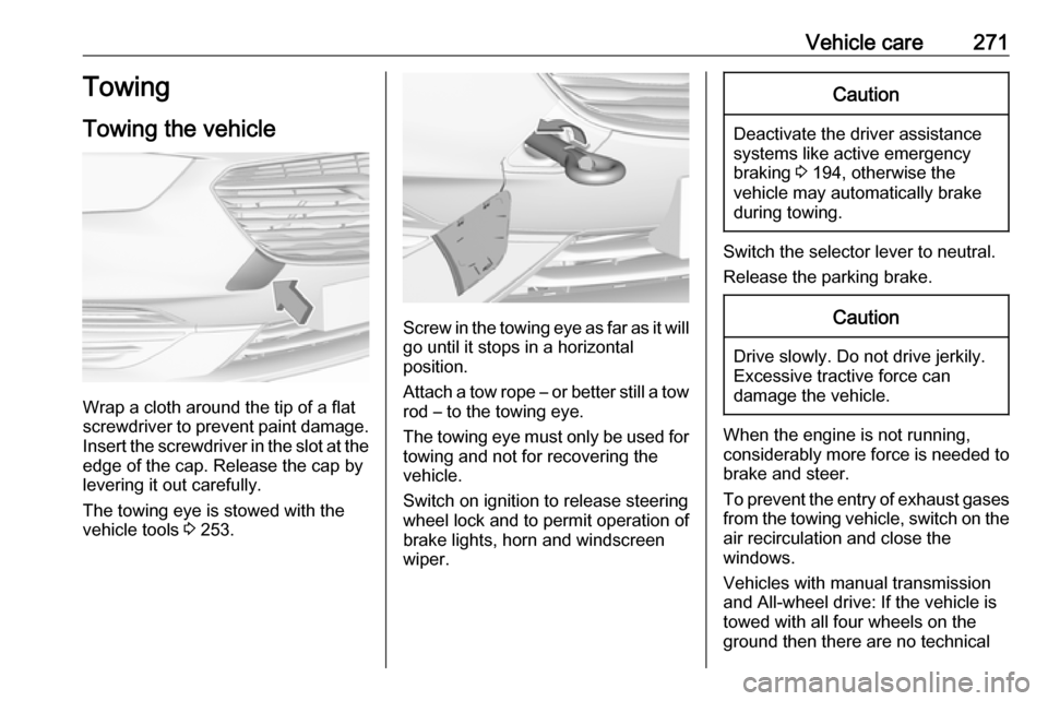
Towing the vehicle
Wrap a cloth around the tip of a flat
screwdriver to prevent paint damage.
Insert the screwdriver in the slot at the
edge of the cap. Release the cap by
levering it out carefully.
The towing eye is stowed with the
vehicle tools 3 253.
Screw in the towing eye as far as it will
go until it stops in a horizontal
position.
Attach a tow rope – or better still a tow
rod – to the towing eye.
The towing eye must only be used for
towing and not for recovering the
vehicle.
Switch on ignition to release steering wheel lock and to permit operation of
brake lights, horn and windscreen
wiper.
Caution
Deactivate the driver assistance
systems like active emergency
braking 3 194, otherwise the
vehicle may automatically brake during towing.
Switch the selector lever to neutral.
Release the parking brake.
Caution
Drive slowly. Do not drive jerkily.
Excessive tractive force can
damage the vehicle.
When the engine is not running,
considerably more force is needed to
brake and steer.
To prevent the entry of exhaust gases from the towing vehicle, switch on the
air recirculation and close the
windows.
Vehicles with manual transmission
and All-wheel drive: If the vehicle is
towed with all four wheels on the
ground then there are no technical