Map OPEL KADETT 1991 Electronic Workshop Manual
[x] Cancel search | Manufacturer: OPEL, Model Year: 1991, Model line: KADETT, Model: OPEL KADETT 1991Pages: 1070, PDF Size: 41.39 MB
Page 1035 of 1070
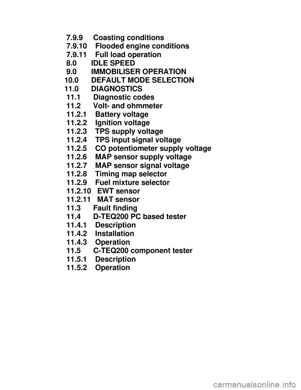
Downloaded from www.Manualslib.com manuals search engine 7.9.9 Coasting conditions
7.9.10 Flooded engine conditions
7.9.11 Full load operation
8.0 IDLE SPEED
9.0 IMMOBILISER OPERATION
10.0 DEFAULT MODE SELECTION
11.0 DIAGNOSTICS
11.1 Diagnostic codes
11.2 Volt- and ohmmeter
11.2.1 Battery voltage
11.2.2 Ignition voltage
11.2.3 TPS supply voltage
11.2.4 TPS input signal voltage
11.2.5 CO potentiometer supply voltage
11.2.6 MAP sensor supply voltage
11.2.7 MAP sensor signal voltage
11.2.8 Timing map selector
11.2.9 Fuel mixture selector
11.2.10 EWT sensor
11.2.11 MAT sensor
11.3 Fault finding
11.4 D-TEQ200 PC based tester
11.4.1 Description
11.4.2 Installation
11.4.3 Operation
11.5 C-TEQ200 component tester
11.5.1 Description
11.5.2 Operation
Page 1037 of 1070

Downloaded from www.Manualslib.com manuals search engine - User selectable spark timing curves for different
fuel octane ratings
- User selectable fuel mixture maps for different
octane ratings
- Automatic default mode selection in the event of
sensor failure allows limp-home operation
- Air-conditioner shutdown control
- Self-diagnostics with fault storage
- Intelligent PC based diagnostics with logging
facility.
- Software immobiliser which prevents hot-wiring
- Repairability. THIS IS NOT A THROW-AWAY UNIT. IT CAN BE REPAIRED AT DUPEC FOR A MINIMAL CHARGE
Page 1039 of 1070
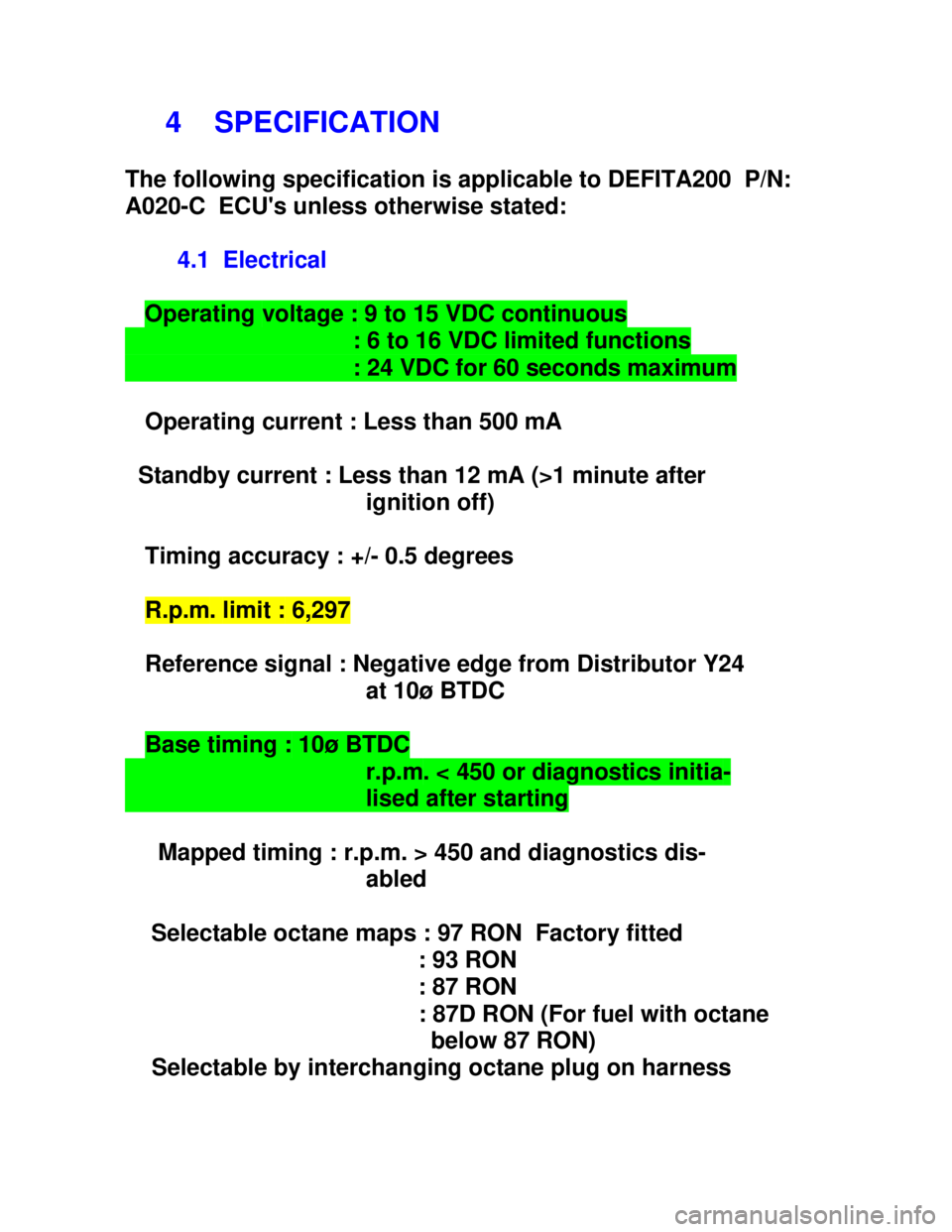
Downloaded from www.Manualslib.com manuals search engine 4 SPECIFICATION
The following specification is applicable to DEFITA200 P/N:
A020-C ECU's unless otherwise stated:
4.1 Electrical
Operating voltage : 9 to 15 VDC continuous : 6 to 16 VDC limited functions : 24 VDC for 60 seconds maximum
Operating current : Less than 500 mA
Standby current : Less than 12 mA (>1 minute after
ignition off)
Timing accuracy : +/- 0.5 degrees
R.p.m. limit : 6,297
Reference signal : Negative edge from Distributor Y24
at 10ø BTDC
Base timing : 10ø BTDC r.p.m. < 450 or diagnostics initia- lised after starting
Mapped timing : r.p.m. > 450 and diagnostics dis-
abled
Selectable octane maps : 97 RON Factory fitted
: 93 RON
: 87 RON
: 87D RON (For fuel with octane
below 87 RON)
Selectable by interchanging octane plug on harness
Page 1040 of 1070

Downloaded from www.Manualslib.com manuals search engine Fuel mixture adjustment : - 15% Leaner
: - 10% Leaner
: - 05% Leaner
: + 05% Richer
: + 10% Richer
: + 15% Richer
: + 20% Richer
: + 25% Richer
Selectable by installing optional
mixture selection plug.
Operation only possible in open
throttle position.
Air-conditioner shut-off : Throttle > 88% open OR
: TPS closed and speed < idle r.p.m.
Fuel injection timing : Synchronous with reference signal
Idle CO adjustment : +/- 15% of base fuel map by means
of CO potentiometer with closed
throttle
Coasting cut-out : 1228 r.p.m. - EWT > 78 øC
: 1755 r.p.m. - EWT = 0 øC
Idle speed : 910 r.p.m. - EWT > 78 øC
: 1300 r.p.m. - EWT = 0 øC
: 1050 r.p.m. - A/C ON (EWT > 78 øC)
: 1495 r.p.m. - A/C ON (EWT = 0 øC)
Idle speed control : By means of stepper motor control
of IACV (Idle Air Control Valve)
Wide Open Throttle (WOT) : Throttle > 72% open
Flood compensation : 0.6x base fuel maps in WOT mode
and r.p.m. < 450
Page 1043 of 1070
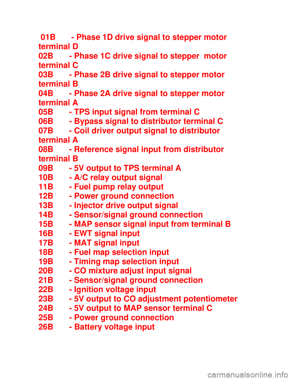
Downloaded from www.Manualslib.com manuals search engine 01B - Phase 1D drive signal to stepper motor
terminal D
02B - Phase 1C drive signal to stepper motor
terminal C
03B - Phase 2B drive signal to stepper motor
terminal B
04B - Phase 2A drive signal to stepper motor
terminal A
05B - TPS input signal from terminal C
06B - Bypass signal to distributor terminal C
07B - Coil driver output signal to distributor
terminal A
08B - Reference signal input from distributor
terminal B
09B - 5V output to TPS terminal A
10B - A/C relay output signal
11B - Fuel pump relay output
12B - Power ground connection
13B - Injector drive output signal
14B - Sensor/signal ground connection
15B - MAP sensor signal input from terminal B
16B - EWT signal input
17B - MAT signal input
18B - Fuel map selection input
19B - Timing map selection input
20B - CO mixture adjust input signal
21B - Sensor/signal ground connection
22B - Ignition voltage input
23B - 5V output to CO adjustment potentiometer
24B - 5V output to MAP sensor terminal C
25B - Power ground connection
26B - Battery voltage input
Page 1044 of 1070
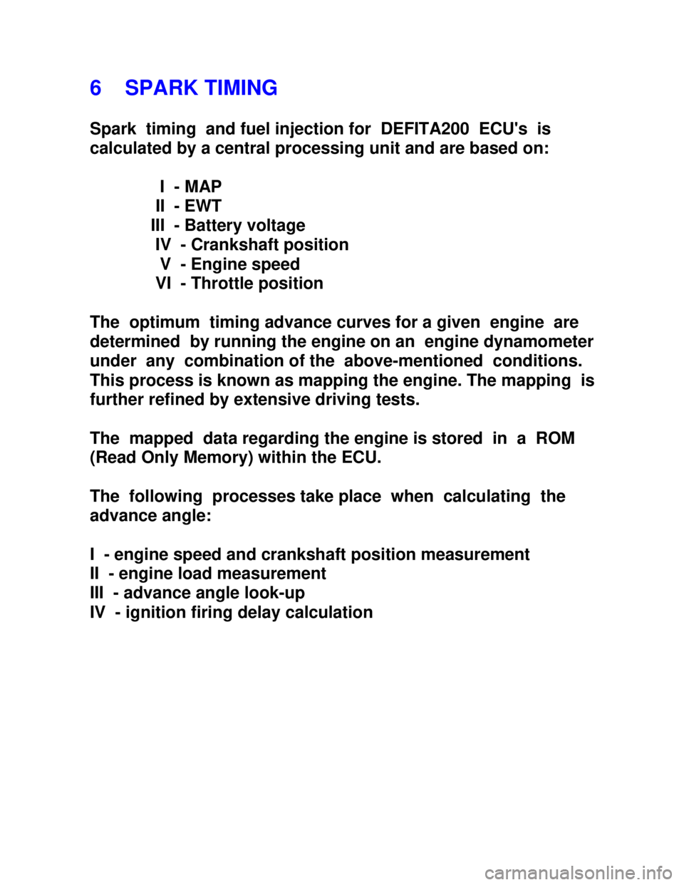
Downloaded from www.Manualslib.com manuals search engine 6 SPARK TIMING
Spark timing and fuel injection for DEFITA200 ECU's is
calculated by a central processing unit and are based on:
I - MAP
II - EWT
III - Battery voltage
IV - Crankshaft position
V - Engine speed
VI - Throttle position
The optimum timing advance curves for a given engine are
determined by running the engine on an engine dynamometer
under any combination of the above-mentioned conditions.
This process is known as mapping the engine. The mapping is
further refined by extensive driving tests.
The mapped data regarding the engine is stored in a ROM
(Read Only Memory) within the ECU.
The following processes take place when calculating the
advance angle:
I - engine speed and crankshaft position measurement
II - engine load measurement
III - advance angle look-up
IV - ignition firing delay calculation
Page 1046 of 1070

Downloaded from www.Manualslib.com manuals search engine 6.3 Engine load measurement
Engine load is measured by an external MAP ( Manifold Abso-
lute Pressure) sensor. Absolute pressure measurement auto-
matically adjust spark timing for altitude changes. It is also
required to determine the air mass for fuel injection
applications.
6.4 Advance angle look-up
The optimum advance angle obtained by mapping the engine
is stored in a matrix (table) having 10 load and 62 r.p.m.
sites. There are thus 620 possible advance angles stored in
ROM for every RON number used. The CPU (Central
Processing Unit) compares the calculated engine speed and
measured load with the site indexes stored in ROM. If an exact
correspond-ing speed and load site are found it uses the
corresponding advance angle in the matrix. In cases where
exact corre- sponding load and r.p.m. sites are not found the
CPU uses linear interpolation to calculate the corresponding
advance angle to be used.
Page 1056 of 1070

Downloaded from www.Manualslib.com manuals search engine 7.8 INJECTION DURATION
The base injection duration for different loads and engine
speeds is calculated and fine tuned by mapping to ensure
that the required A/F ratio is obtained under static operat-
ing conditions. (Lambda = 1) Injection durations vary from 1to 5 milliseconds.
The following operating parameters were assumed for the
purpose of obtaining the base map:
a) Continuous fuel flow rates with battery voltage
at 14 volt.
b) Intake air temperature at 303.7 øKelvin.
c) Zero injector delay.
d) One injection cycle per intake stroke.
7.9 CORRECTION FACTORS
Correction factors are applied to the base map to correct
for injection hardware deficiencies and engine operating
conditions.
7.9.1 Injection hardware deficiencies.
The reduced fuel flow rate at low battery voltages necessi-
tates an increase in the injection duration. The factor by
which the injection durations from the base map has to be
multiplied is obtained by normalising the fuel flow rate at
different battery voltages with respect to 14.0 volt.
In addition to the above multiplication factor the base map
injection times are further increased by the injector delays
to ensure that the correct quantity of fuel is injected.
Page 1057 of 1070

Downloaded from www.Manualslib.com manuals search engine 7.9.2 Engine operating conditions.
The following engine operating conditions require additional
modifications to the base injection map.
7.9.3 Intake air temperature.
The oxygen content of the intake air is proportional to the
air density and inversely proportional to the air tempera-
ture. It is therefore necessary to correct the base map for
intake air temperature variations. An air intake tempera-
ture correction factor which is normalised with respect to
303.7øK is therefore used.
7.9.4 Engine temperature.
Cold engines exhibit more friction and therefore require
slightly richer A/F ratios to ensure smooth running. Cor-
rections are made for engine temperatures from -13øC to
110øC and normalised with respect to 100øC.
Cold intake manifolds result in considerable wall-wetting
which means that all the injected fuel does not atomise to
form a combustionable mixture. Additional fuel has to be
injected to overcome this effect.
Page 1058 of 1070

Downloaded from www.Manualslib.com manuals search engine 7.9.5 Cold starting conditions.
Definition: Engine speed < 450 r.p.m.
During cold start conditions the low inlet manifold tempera-
tures cause considerable fuel condensation on the inner
walls of the manifold. This condition is known as wall
wetting. To ensure correct A/F ratios it is necessary to
increase the quantity of fuel injected during cold starting
conditions to counteract wall wetting. A correction factor
is applied to the base map for engine temperatures between
-40øC and 100øC.
To prevent the engine from flooding the enrichment factor is
not only engine temperature dependent, but also time depend-
ent. This is implemented by reducing the enrichment factor
over a number of crankshaft revolutions, regardless of
engine temperature. If the ignition is turned off and an
attempt is made to re-start the engine the process is re-
peated.
7.9.6 Post start and warm-up conditions.
Definition: Engine speed > 450 r.p.m.
Engine temperature < 80øC
During these conditions the engine temperature is monitored
and the A/F ratio is decreased by lengthening the base map
injection duration to ensure smooth running of the engine
and to compensate for inlet manifold wall-wetting.