Map sensor OPEL KADETT 1991 Electronic Workshop Manual
[x] Cancel search | Manufacturer: OPEL, Model Year: 1991, Model line: KADETT, Model: OPEL KADETT 1991Pages: 1070, PDF Size: 41.39 MB
Page 1035 of 1070
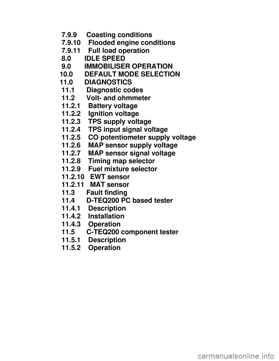
Downloaded from www.Manualslib.com manuals search engine 7.9.9 Coasting conditions
7.9.10 Flooded engine conditions
7.9.11 Full load operation
8.0 IDLE SPEED
9.0 IMMOBILISER OPERATION
10.0 DEFAULT MODE SELECTION
11.0 DIAGNOSTICS
11.1 Diagnostic codes
11.2 Volt- and ohmmeter
11.2.1 Battery voltage
11.2.2 Ignition voltage
11.2.3 TPS supply voltage
11.2.4 TPS input signal voltage
11.2.5 CO potentiometer supply voltage
11.2.6 MAP sensor supply voltage
11.2.7 MAP sensor signal voltage
11.2.8 Timing map selector
11.2.9 Fuel mixture selector
11.2.10 EWT sensor
11.2.11 MAT sensor
11.3 Fault finding
11.4 D-TEQ200 PC based tester
11.4.1 Description
11.4.2 Installation
11.4.3 Operation
11.5 C-TEQ200 component tester
11.5.1 Description
11.5.2 Operation
Page 1037 of 1070

Downloaded from www.Manualslib.com manuals search engine - User selectable spark timing curves for different
fuel octane ratings
- User selectable fuel mixture maps for different
octane ratings
- Automatic default mode selection in the event of
sensor failure allows limp-home operation
- Air-conditioner shutdown control
- Self-diagnostics with fault storage
- Intelligent PC based diagnostics with logging
facility.
- Software immobiliser which prevents hot-wiring
- Repairability. THIS IS NOT A THROW-AWAY UNIT. IT CAN BE REPAIRED AT DUPEC FOR A MINIMAL CHARGE
Page 1043 of 1070
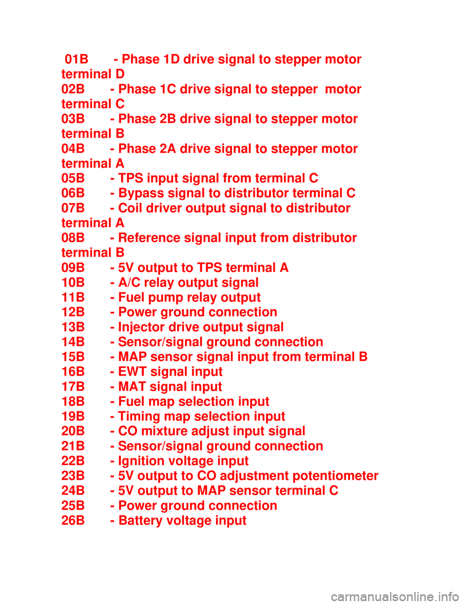
Downloaded from www.Manualslib.com manuals search engine 01B - Phase 1D drive signal to stepper motor
terminal D
02B - Phase 1C drive signal to stepper motor
terminal C
03B - Phase 2B drive signal to stepper motor
terminal B
04B - Phase 2A drive signal to stepper motor
terminal A
05B - TPS input signal from terminal C
06B - Bypass signal to distributor terminal C
07B - Coil driver output signal to distributor
terminal A
08B - Reference signal input from distributor
terminal B
09B - 5V output to TPS terminal A
10B - A/C relay output signal
11B - Fuel pump relay output
12B - Power ground connection
13B - Injector drive output signal
14B - Sensor/signal ground connection
15B - MAP sensor signal input from terminal B
16B - EWT signal input
17B - MAT signal input
18B - Fuel map selection input
19B - Timing map selection input
20B - CO mixture adjust input signal
21B - Sensor/signal ground connection
22B - Ignition voltage input
23B - 5V output to CO adjustment potentiometer
24B - 5V output to MAP sensor terminal C
25B - Power ground connection
26B - Battery voltage input
Page 1046 of 1070

Downloaded from www.Manualslib.com manuals search engine 6.3 Engine load measurement
Engine load is measured by an external MAP ( Manifold Abso-
lute Pressure) sensor. Absolute pressure measurement auto-
matically adjust spark timing for altitude changes. It is also
required to determine the air mass for fuel injection
applications.
6.4 Advance angle look-up
The optimum advance angle obtained by mapping the engine
is stored in a matrix (table) having 10 load and 62 r.p.m.
sites. There are thus 620 possible advance angles stored in
ROM for every RON number used. The CPU (Central
Processing Unit) compares the calculated engine speed and
measured load with the site indexes stored in ROM. If an exact
correspond-ing speed and load site are found it uses the
corresponding advance angle in the matrix. In cases where
exact corre- sponding load and r.p.m. sites are not found the
CPU uses linear interpolation to calculate the corresponding
advance angle to be used.
Page 1063 of 1070

Downloaded from www.Manualslib.com manuals search engine 10 DEFAULT MODE SELECTION
When the ECU detects a faulty signal from one of its sensors
it will substitute a default signal value to enable the
vehicle to be driven with degraded performance (see para-
graph 10.1).
Faulty sensor Substitute value/sensor
_____________________________________________________
______
EWT Warm engine - 100 øC
MAT 31 øC
Fuel map selector Zero percent enrichment
Timing map selector Map T1 - RON 87D
TPS Idle speed - 1,000 to
2,000 r.p.m.
MAP TPS and idle speed -
1,000 to 2,000 r.p.m.
Disable distributor
bypass operation and
fix spark timing at
10ø BTDC
CO potentiometer Zero percent
Page 1065 of 1070

Downloaded from www.Manualslib.com manuals search engine DIAGNOSTIC CODES
Code Cause
_____________________________________________________
14 Coolant temperature sensor voltage too low
15 Coolant temperature sensor voltage too high
21 TPS voltage too high
22 TPS voltage too low
25 MAT sensor voltage too low
26 MAT sensor voltage too high
33 MAP sensor voltage too high
34 MAP sensor voltage too low
35 Idle control stepper motor failure
36 Timing map selector error
42 Reference signal error/Engine stall
(Diagnostic lamp will not turn ON)
44 Fuel map selector error
48 Battery voltage too low
49 Battery voltage too high
65 CO potentiometer voltage out of range
Page 1067 of 1070

Downloaded from www.Manualslib.com manuals search engine 11.2.5 CO potentiometer supply voltage: The voltage
between
terminal 23B and signal ground should be between 4.7 and
5.2 volt.
11.2.6 MAP sensor supply voltage: The voltage between
terminal
24B and signal ground should be between 4.7 and 5.2 volt.
11.2.7 MAP sensor signal voltage: The voltage between
terminal
15B and signal ground with ignition on should be:
MAP signal voltage Manifold absolute pressure
_____________________________________________________
___
1.00 20 kPa
2.00 40 kPa
3.00 60 kPa
4.00 80 kPa
4.50 90 kPa
5.00 100 kPa
A general tolerance of +/- 5% exists on the above voltages.