ABS OPEL KARL 2017.5 Owner's Manual
[x] Cancel search | Manufacturer: OPEL, Model Year: 2017.5, Model line: KARL, Model: OPEL KARL 2017.5Pages: 203, PDF Size: 5.4 MB
Page 62 of 203

60Instruments and controlsInstruments and
controlsControls ....................................... 61
Steering wheel adjustment ........61
Steering wheel controls .............61
Heated steering wheel ...............61
Horn ........................................... 62
Windscreen wiper/washer .........62
Rear window wiper/washer .......63
Outside temperature ..................63
Clock ......................................... 63
Power outlets ............................. 65
Cigarette lighter ......................... 65
Ashtrays .................................... 65
Warning lights, gauges and indi‐ cators ........................................... 65
Instrument cluster ......................65
Speedometer ............................. 65
Odometer .................................. 66
Trip odometer ............................ 66
Tachometer ............................... 66
Fuel gauge ................................ 66
Fuel selector .............................. 67
Engine coolant temperature gauge ....................................... 68
Service display .......................... 68Control indicators ......................69
Turn signal ................................. 71
Seat belt reminder .....................72
Airbag and belt tensioners .........72
Airbag deactivation ....................72
Charging system .......................73
Malfunction indicator light ..........73
Service vehicle soon .................73
Brake and clutch system ...........73
Operate pedal ............................ 73
Antilock brake system (ABS) .....74
Gear shifting .............................. 74
Power steering .......................... 74
Lane departure warning ............74
Ultrasonic parking assist ...........74
Electronic Stability Control off ...74
Electronic Stability Control and Traction Control system ...........74
Traction Control system off .......75
Engine coolant temperature ......75
Tyre pressure monitoring system ...................................... 75
Engine oil pressure ....................75
Low fuel ..................................... 76
Immobiliser ................................ 76
Reduced engine power .............76
Exterior light .............................. 76
High beam ................................. 76
Fog light ..................................... 76
Rear fog light ............................. 76Cruise control............................ 76
Speed limiter ............................. 76
Bonnet open .............................. 76
Door open .................................. 77
Information displays .....................77
Driver Information Centre ..........77
Info display ................................ 82
Vehicle messages ........................83
Warning chimes .........................85
Battery voltage .......................... 85
Vehicle personalisation ................86
Telematics service .......................88
OnStar ....................................... 88
Page 73 of 203

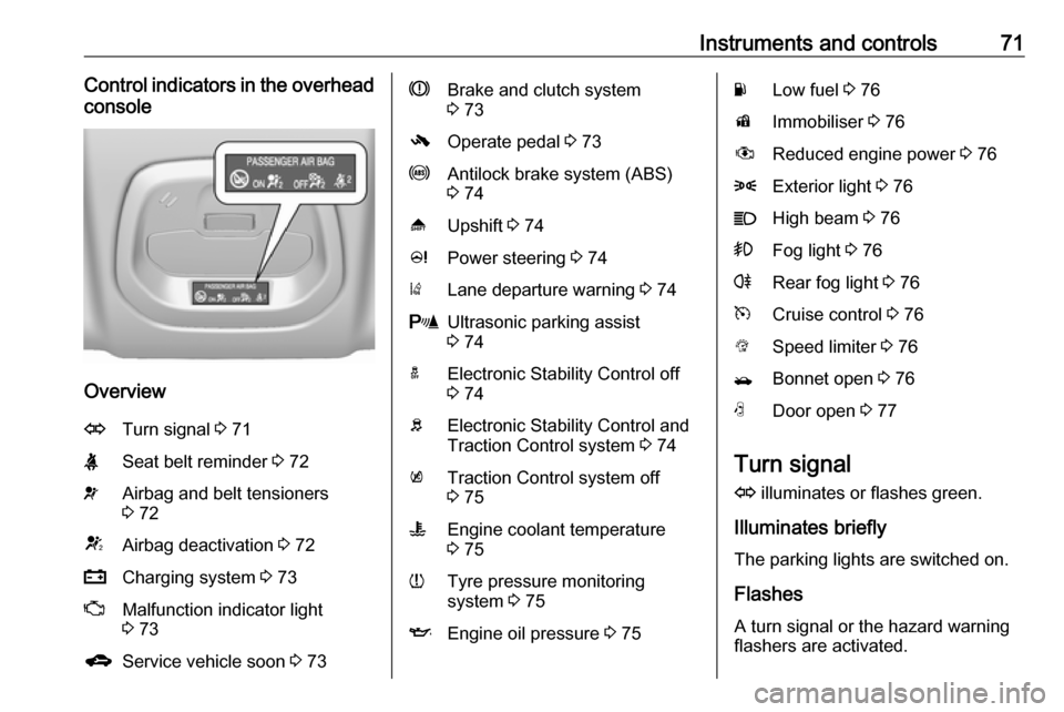
Instruments and controls71Control indicators in the overheadconsole
Overview
OTurn signal 3 71XSeat belt reminder 3 72vAirbag and belt tensioners
3 72VAirbag deactivation 3 72pCharging system 3 73ZMalfunction indicator light
3 73gService vehicle soon 3 73RBrake and clutch system
3 73-Operate pedal 3 73uAntilock brake system (ABS)
3 74[Upshift 3 74cPower steering 3 74)Lane departure warning 3 74rUltrasonic parking assist
3 74aElectronic Stability Control off
3 74bElectronic Stability Control and
Traction Control system 3 74kTraction Control system off
3 75WEngine coolant temperature
3 75wTyre pressure monitoring
system 3 75IEngine oil pressure 3 75YLow fuel 3 76dImmobiliser 3 76#Reduced engine power 3 768Exterior light 3 76CHigh beam 3 76>Fog light 3 76rRear fog light 3 76mCruise control 3 76LSpeed limiter 3 76/Bonnet open 3 76NDoor open 3 77
Turn signal
O illuminates or flashes green.
Illuminates briefly
The parking lights are switched on.
Flashes
A turn signal or the hazard warning
flashers are activated.
Page 76 of 203

74Instruments and controlsFlashes
Pedal must be depressed to start the engine with the key 3 18, 3 110.
Antilock brake system (ABS)
u illuminates yellow.
Illuminates for a few seconds after the ignition is switched on. The system is
ready for operation when the control
indicator extinguishes.
If the control indicator does not go out after a few seconds, or if it illuminates while driving, there is a fault in the
ABS. The brake system remains
operational but without ABS
regulation.
Antilock brake system 3 119.
Gear shifting
[ with the number of a higher gear is
indicated, when upshifting is
recommended for fuel saving
reasons.Power steering
c illuminates yellow.
Illuminates with power steering
disabled
Failure in the power steering system.
Consult a workshop.
Illumination of c and b
simultaneously
Power steering system must be
calibrated, system calibration 3 123.
Lane departure warning ) illuminates green or flashes yellow.
Illuminates green
System is switched on and ready to
operate.
Flashes yellow
System recognises an unintended
lane change.
Lane departure warning 3 128.Ultrasonic parking assist
r illuminates yellow.
Fault in system
or
Fault due to sensors that are dirty or
covered by ice or snow
or
Interference due to external sources of ultrasound. Once the source of
interference is removed, the system
will operate normally.
Have the cause of the fault in the
system remedied by a workshop.
Ultrasonic parking assist 3 127.
Electronic Stability Control off
t illuminates yellow.
The system is deactivated.
Electronic Stability Control and Traction Control system
b flashes or illuminates yellow.
Page 93 of 203

Instruments and controls91Stolen vehicle assistance
If the vehicle is stolen, report the theft
to the authorities and request OnStar
stolen vehicle assistance. Use any
phone to call an advisor. Find the
respective OnStar phone number on
our country-specific website.
OnStar can provide support in
locating and recovering the vehicle.Theft alert
When the anti-theft alarm system is
triggered, a notification is sent to
OnStar. You are then informed about
this event by text message or email.Restart prevention
By sending remote signals, OnStar can prevent the vehicle from
restarting once it has been turned off.
On-demand diagnostics
At any time e.g. if the vehicle displays a vehicle message, press Z to
contact an advisor and ask to
complete a real-time diagnostic check
to directly determine the issue.
Depending on the results, the advisor
will provide further support.
Diagnostic report
The vehicle automatically transmits
diagnostic data to OnStar which
sends a monthly email report to you
and your preferred workshop.
Note
The workshop notification function
can be disabled in your account.
The report contains the status of key
operating systems of the vehicle like
engine, transmission, airbags, ABS,
and other major systems. It also
provides information on possible
maintenance items and tyre pressure
(only with tyre pressure monitoring
system).
To look at the information in greater
detail, select the link within the email and log in to your account.
Destination download
A desired destination can be directly
downloaded to the navigation system.
Press Z to call an advisor and
describe the destination or point of interest.The advisor can look up any address
or point of interest and directly send
the destination to the built-in
navigation system.
OnStar settings
OnStar PIN
To have full access to all OnStar
services, a four-digit PIN is required.
The PIN has to be personalised when first talking to an advisor.
To change the PIN, press Z to call an
advisor.
Account data
An OnStar subscriber has an account
where all the data is stored. To
request a change of the account
information, press Z and talk to an
advisor or log in to your account.
If the OnStar service is used on
another vehicle, press Z and request
that the account be transferred to the
new vehicle.
Page 121 of 203

Driving and operating119Have the cause of the fault remedied
by a workshop.Brakes
The brake system comprises twoindependent brake circuits.
If a brake circuit fails, the vehicle can
still be braked using the other brake
circuit. However, braking effect is
achieved only when the brake pedal
is depressed firmly. Considerably
more force is needed for this. The
braking distance is extended. Seek
the assistance of a workshop before
continuing the journey.
When the engine is not running, the
support of the brake servo unit
disappears once the brake pedal has
been depressed once or twice.
Braking effect is not reduced, but
braking requires significantly greater
force. It is especially important to bear this in mind when being towed.
Control indicator R 3 73.
Antilock brake system
Antilock brake system (ABS)
prevents the wheels from locking.ABS starts to regulate brake pressure as soon as a wheel shows a tendency to lock. The vehicle remains
steerable, even during hard braking.
ABS control is made apparent
through a pulse in the brake pedal
and the noise of the regulation
process.
For optimum braking, keep the brake
pedal fully depressed throughout the
braking process, despite the fact that
the pedal is pulsating. Do not reduce
the pressure on the pedal.
After starting-off the system performs a self-test which may be audible.
Control indicator u 3 74.
Adaptive brake light
During full braking, all three brake
lights flash for the duration of ABS
control.
Page 122 of 203

120Driving and operatingFault9Warning
If there is a fault in the ABS, the
wheels may be liable to lock due
to braking that is heavier than
normal. The advantages of ABS are no longer available. During
hard braking, the vehicle can no longer be steered and may
swerve.
Have the cause of the fault remedied
by a workshop.
Parking brake
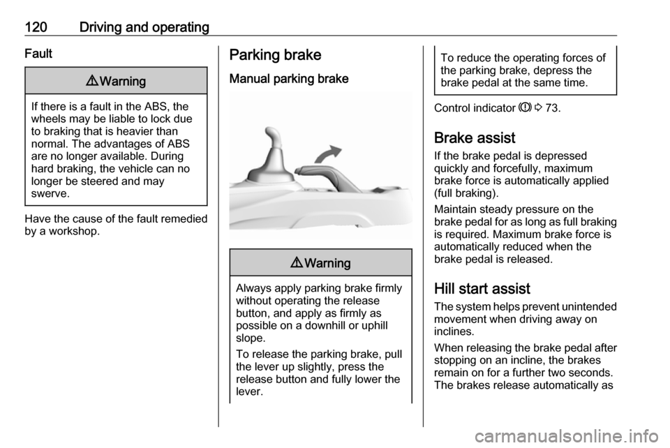
Manual parking brake9 Warning
Always apply parking brake firmly
without operating the release
button, and apply as firmly as
possible on a downhill or uphill
slope.
To release the parking brake, pull
the lever up slightly, press the
release button and fully lower the
lever.
To reduce the operating forces of
the parking brake, depress the
brake pedal at the same time.
Control indicator R 3 73.
Brake assist
If the brake pedal is depressed
quickly and forcefully, maximum
brake force is automatically applied
(full braking).
Maintain steady pressure on the
brake pedal for as long as full braking is required. Maximum brake force is
automatically reduced when the
brake pedal is released.
Hill start assist
The system helps prevent unintended movement when driving away on
inclines.
When releasing the brake pedal after
stopping on an incline, the brakes
remain on for a further two seconds.
The brakes release automatically as
Page 145 of 203

Vehicle care143
Batteries do not belong in household
waste. They must be disposed of at
an appropriate recycling collection
point.
Laying up the vehicle for more than
four weeks can lead to vehicle battery
discharge. Disconnect the clamp from
the negative terminal of the vehicle
battery.
Ensure the ignition is switched off
before connecting or disconnecting
the vehicle battery.
Battery discharge protection 3 98.
Disconnecting the battery
If the vehicle's battery is to be
disconnected (e.g. for maintenance
work), the alarm siren must be
deactivated as follows: Switch the
ignition on then off, then disconnect
the vehicle's battery within
15 seconds.
Replacing the vehicle battery
Note
Any deviation from the instructions
given in this section may lead to
temporary deactivation of the stop-
start system.
When the vehicle battery is being
replaced, please ensure that there
are no open ventilation holes in the
vicinity of the positive terminal. If a
ventilation hole is open in this area, it
must be closed off with a dummy cap,
and the ventilation in the vicinity of the negative terminal must be opened.
In vehicles with an AGM (Absorptive
Glass Mat) battery, make sure to
have the battery replaced with
another AGM battery.
We recommend the use of an original Opel battery.
Note
Using an AGM vehicle battery
different from the original Opel
vehicle battery may result in a lower
performance.We recommend that you have the
vehicle battery replaced by a
workshop.
Charging the vehicle battery9 Warning
On vehicles with stop-start
system, ensure that the charging potential does not exceed 14.6
volts when using a battery
charger. Otherwise the battery
might be damaged.
Jump starting 3 170.
Stop-start system 3 111.
Page 155 of 203

Vehicle care153No.Circuit1Tailgate2–3Heated rear window4Heated exterior mirror5Sunroof6Transmission control module7Engine control module8–9ABS10Body control module, voltage11Rear view camera12–13–14Engine control module/Trans‐
mission control module15Injection system/Starter16Fuel pump17Engine control module1No.Circuit18Engine control module219Injection system/Ignition20Air conditioning system21Battery sensor22Electric steering column lock23Cooling fan low24–25Exterior mirror switch26Engine control module/Manual
transmission automated
module27Fuel system28Brake system29Seat occupancy recognition30Headlight range adjustment31Horn32Front fog light33High beam leftNo.Circuit34High beam right35–36Rear wiper37Cornering light left38Washer system39Cornering light right40–41–42Starter 243Instrument panel44Manual transmission auto‐
mated, DC-DC converter45Starter 146ABS47Cooling fan high48Front wiper49Body control module/Retained
power off
Page 156 of 203

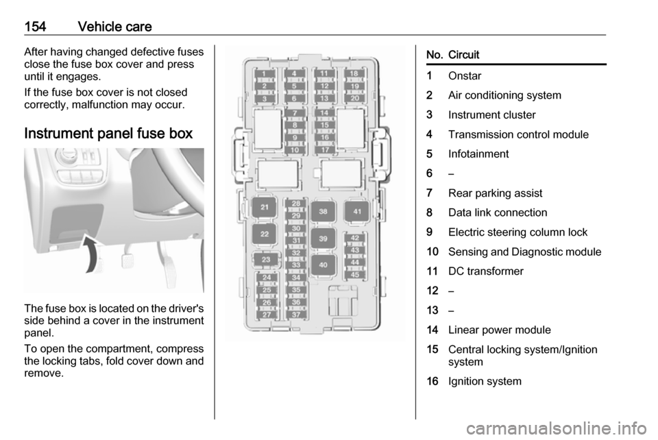
154Vehicle careAfter having changed defective fusesclose the fuse box cover and press
until it engages.
If the fuse box cover is not closed
correctly, malfunction may occur.
Instrument panel fuse box
The fuse box is located on the driver's
side behind a cover in the instrument
panel.
To open the compartment, compress
the locking tabs, fold cover down and
remove.
No.Circuit1Onstar2Air conditioning system3Instrument cluster4Transmission control module5Infotainment6–7Rear parking assist8Data link connection9Electric steering column lock10Sensing and Diagnostic module11DC transformer12–13–14Linear power module15Central locking system/Ignition
system16Ignition system
Page 174 of 203

172Vehicle care
2. Screw in the towing eye as far asit will go until it stops in a
horizontal position.
3. Attach a tow rope – or better still a
tow rod – to the towing eye.
General
The towing eye must only be used for
towing and not for recovering the
vehicle.
Switch on ignition to release steering
wheel lock and to permit operation of
brake lights, horn and windscreen
wiper.
Transmission in neutral.Caution
Drive slowly. Do not drive jerkily.
Excessive tractive force can
damage the vehicle.
When the engine is not running,
considerably more force is needed to
brake and steer.
To prevent the entry of exhaust gases from the towing vehicle, switch on the
air recirculation and close the
windows.
The vehicle must be towed facing
forward, not faster than 88 km/h. In all
other cases and when the
transmission is defective, the front
axle must be raised off the ground.
Seek the assistance of a workshop.
After towing, unscrew the towing eye.
Insert cap and engage in the front
bumper.
Appearance care
Exterior care
Locks The locks are lubricated at the factoryusing a high quality lock cylinder
grease. Use a de-icing agent only
when absolutely necessary, as this
has a degreasing effect and impairs
lock function. After using a de-icing
agent, have the locks regreased by a workshop.
Washing The paintwork of your vehicle is
exposed to environmental influences.
Wash and wax your vehicle regularly. When using automatic vehicle
washes, select a programme that
includes waxing.
Bird droppings, dead insects, resin,
pollen and the like should be cleaned
off immediately, as they contain
aggressive constituents which can
cause paint damage.