alternator belt OPEL MANTA 1973 Service Manual
[x] Cancel search | Manufacturer: OPEL, Model Year: 1973, Model line: MANTA, Model: OPEL MANTA 1973Pages: 625, PDF Size: 17.22 MB
Page 18 of 625
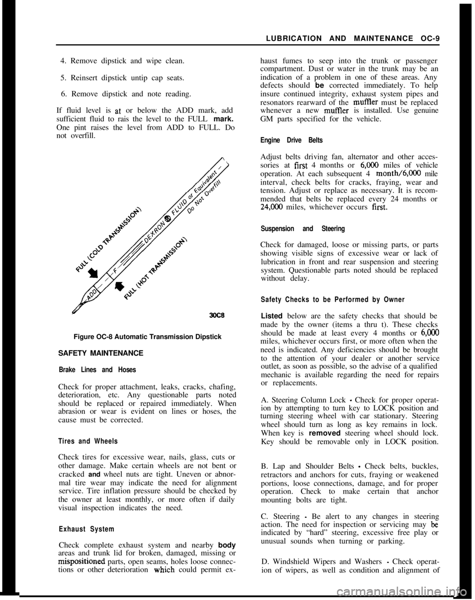
LUBRICATION AND MAINTENANCE OC-9
4. Remove dipstick and wipe clean.
5. Reinsert dipstick untip cap seats.
6. Remove dipstick and note reading.
If fluid level is at, or below the ADD mark, add
sufficient fluid to rais the level to the FULL mark.
One pint raises the level from ADD to FULL. Do
not overfill.
3OC8Figure OC-8 Automatic Transmission Dipstick
SAFETY MAINTENANCE
Brake Lines and HosesCheck for proper attachment, leaks, cracks, chafing,
deterioration, etc. Any questionable parts noted
should be replaced or repaired immediately. When
abrasion or wear is evident on lines or hoses, the
cause must be corrected.
Tires and WheelsCheck tires for excessive wear, nails, glass, cuts or
other damage. Make certain wheels are not bent or
cracked and wheel nuts are tight. Uneven or abnor-
mal tire wear may indicate the need for alignment
service. Tire inflation pressure should be checked by
the owner at least monthly, or more often if daily
visual inspection indicates the need.
Exhaust SystemCheck complete exhaust system and nearby body
areas and trunk lid for broken, damaged, missing orm&positioned parts, open seams, holes loose connec-
tions or other deterioration wiuch could permit ex-haust fumes to seep into the trunk or passenger
compartment. Dust or water in the trunk may be an
indication of a problem in one of these areas. Any
defects should be corrected immediately. To help
insure continued integrity, exhaust system pipes and
resonators rearward of the muftler must be replaced
whenever a new mufIler is installed. Use genuine
GM parts specified for the vehicle.
Engine Drive BeltsAdjust belts driving fan, alternator and other acces-
sories at first 4 months or
6,ooO miles of vehicle
operation. At each subsequent 4 month/6,000 mile
interval, check belts for cracks, fraying, wear and
tension. Adjust or replace as necessary. It is recom-
mended that belts be replaced every 24 months or
24,C00 miles, whichever occurs first.
Suspension and SteeringCheck for damaged, loose or missing parts, or parts
showing visible signs of excessive wear or lack of
lubrication in front and rear suspension and steering
system. Questionable parts noted should be replaced
without delay.
Safety Checks to be Performed by OwnerListed below are the safety checks that should be
made by the owner (items a thru t). These checks
should be made at least every 4 months or
6,ooOmiles, whichever occurs first, or more often when the
need is indicated. Any deficiencies should be brought
to the attention of your dealer or another service
outlet, as soon as possible, so the advise of a qualified
mechanic is available regarding the need for repairs
or replacements.
A. Steering Column Lock
_ Check for proper operat-
ion by attempting to turn key to LOCK position and
turning steering wheel with car stationary. Steering
wheel should turn as long as key remains in lock.
When key is removed steering wheel should lock.
Key should be removable only in LOCK position.
B. Lap and Shoulder Belts
- Check belts, buckles,
retractors and anchors for cuts, fraying or weakened
portions, loose connections, damage, and for proper
operation. Check to make certain that anchor
mounting bolts are tight.
C. Steering
- Be alert to any changes in steering
action. The need for inspection or servicing may
beindicated by “hard” steering, excessive free play or
unusual sounds when turning or parking.
D. Windshield Wipers and Washers
- Check operat-
ion of wipers, as well as condition and alignment of
Page 50 of 625
CHARGING SYSTEMlD- 29
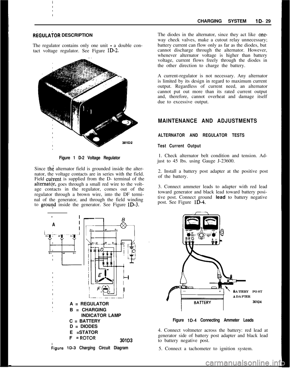
REGULAiOR DESCRIPTION
The regulator contains only one unit - a double con-
tact voltage regulator. See Figure
lD-2.
I Figure 1 D-2 Voltage Regulator
Since th< alternator field is grounded inside the alter-
nator, the voltage contacts are in series with the field.
Field
&rent is supplied from the D- terminal of the
alter”@, goes through a small red wire to the volt-
age contacts in the regulator, comes out of the
regulator through a brown wire, into the DF termi-
nal of the generator, and through the field winding to
grouqd inside the generator. See Figure lD-3.
:
,
!
/ I
’ A I
j
/ I
-
IF
O?
i 2
j
:
:
k
I
I
.i
A = REGULATOR
B = CHARGING
INDICATOR LAMP
C = BATTERY D = DIODES
E =STATOR
I
I F
=ROTOR301D3
kigure
lD-3 Charging Circuit Diagram
The diodes in the alternator, since they act like one-
way check valves, make a cutout relay unnecessary;
battery current can flow only as far as the diodes, but
cannot discharge through the alternator. However,
whenever alternator voltage is higher than battery
voltage, current flows freely through the diodes in
the other direction to charge the battery.
A current-regulator is not necessary. Any alternator
is limited by its design in regard to maximum current
output. Regardless of current need, an alternator
cannot put out more than its rated current output
and, therefore, cannot overheat and damage itself
due to excessive output.
MAINTENANCE AND ADJUSTMENTS
ALTERNATOR AND REGULATOR TESTS
Test Current Output
1. Check alternator belt condition and tension. Ad-
just to 45 lbs. using Gauge J-23600.
2. Install a battery post adapter at the positive post
of the battery.
3. Connect ammeter leads to adapter with red lead
toward generator and black lead toward battery posi-
tive post. Connect ground
lead to battery negative
post. See Figure
lD-4.
BATTERY POST
ADAPTER
SOID
Figure lD-4 Connecting Ammeter Leads
4. Connect voltmeter across the battery: red lead at
generator side of battery post adapter and black lead
to battery negative post.
5. Connect a tachometer to ignition system.
Page 51 of 625
i
1 D- 301973 OPEL SERVICE MANUAL
6. Make sure all electrical accessories are turned (lff.
Start engine with battery post adapter switch closed;
open switch as soon as engine
iS: started.
7. Adjust engine speed to 2500 RPM.
8. Turn tester control knob to “LOAD” position
aid
adjust knob to obtain highest possible ammeter r&d-
ing. Output must be 30 amperes minimum. If
outcut
is okay, proceed to voltage regulator test below. j
/.9. If output is low, defect may be in alternator or m
regulator. To eliminate regulator, supply field &-
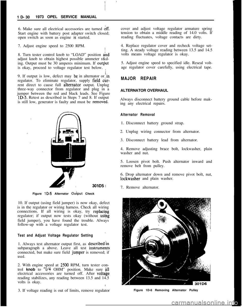
rent direct to cause full alternat,or output. Unplug
three-way connector from regulator and plug in a
jumper between the red and black leads. See Figure
lD-5. Retest as described in Steps 7 and 8. If output
is still low, generator is faulty and must be
remov&d.
301D5 :
Figure lD-5 Alternator Ouiput Check I
10. If output (using field jumper) is now okay, defect
is in the regulator or wiring harness. Check all wiring
connections. If all wiring is okay, try
replac/~g
regulator; if output now tests okay (without
uslpg
field jumper), you have found the trouble. Always
follow-up with a voltage regulator test.
Test and Adjust Voltage Regulator Setting
1. Always test alternator output first, as describedlin
subparagraph a above. Leave all test
instrumeqts
connected, but make sure field
jumper is removed; if
used.
2. With engine speed at 2500 RPM, turn tester con-
trol
knob to “l/4 OHM” position. Make sure ill
electrical accessories are turned off. After volt&e
reading stabilizes, any reading between 13.5 and 14.5
volts is okay.
3. If voltage reading is out of limits, remove regulator cover and adjust voltage regulator armature spring
tension to obtain a middle reading of 14.0 volts. If
reading fluctuates, voltage contacts are dirty.
4. Replace regulator cover and recheck voltage set- ting. A steady voltage reading between 13.5 and 14.5
volts means voltage regulator is okay.
5. Adjust engine speed to specified idle. Reseal volt-
age regulator cover carefully, using electrical tape.
MAJOR REPAIR
ALTERNATOR OVERHAUL
Always disconnect battery ground cable before mak-
ing any electrical repairs.
Alternator Removal
1. Disconnect battery ground strap.
2. Unplug wiring connector from alternator. 3. Disconnect battery lead from alternator.
4. Remove adjusting brace bolt, lockwasher, plain
washer and nut.
5. Loosen pivot bolt. Push alternator inward and
remove belt from pulley.
6. Drop alternator down and remove pivot bolt, nut,
lockwasher and plain washer.
7. Remove alternator.
Figure 1D-6 Removing Alternator Pulley
Page 56 of 625
CHARGING SYSTEMlD- 35
’Figure lD-25 Installing Diode
I
7. Instail rotor together with drive end frame intostator and assemble generator in reverse order ofdisasse+bly. Make sure marks made during disas-
sembly
+-ire aligned.
8. Insta!l pulley and fan. Tighten nut to 30 lb.ft.
9. Test benerator on test bench, if available. If not,
install alternator on car and test.
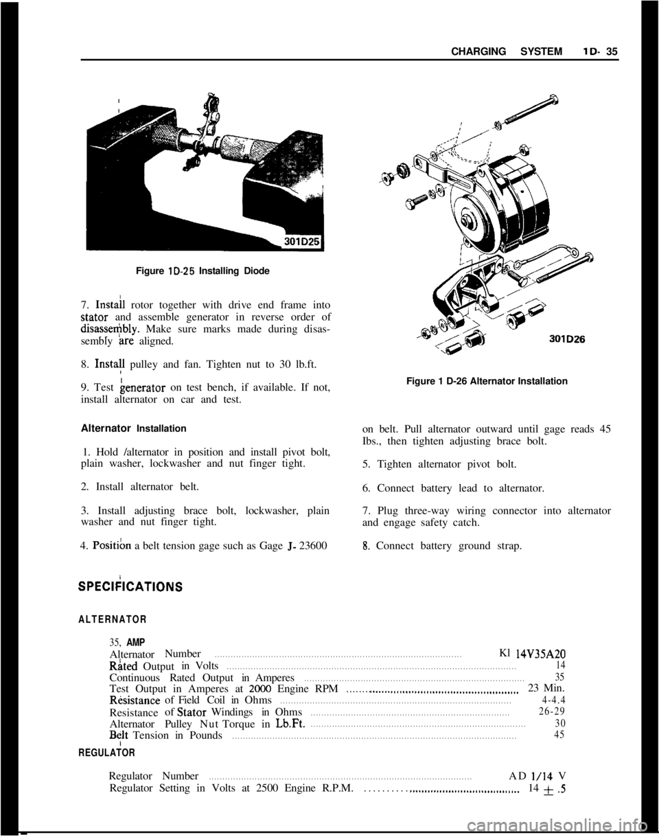
Alternator Installation
1. Hold /alternator in position and install pivot bolt,
plain washer, lockwasher and nut finger tight.
2. Install alternator belt.
3. Install adjusting brace bolt, lockwasher, plain
washer and nut finger tight.
4.
Posit& a belt tension gage such as Gage J- 23600Figure 1 D-26 Alternator Installation
on belt. Pull alternator outward until gage reads 45
Ibs., then tighten adjusting brace bolt.
5. Tighten alternator pivot bolt.
6. Connect battery lead to alternator.
7. Plug three-way wiring connector into alternator
and engage safety catch.8. Connect battery ground strap.SPECkICATIONS
ALTERNATOR
35, AMPAlternatorNumberRated
. . . . . . . . . . . . . . . . . . . . . . . . . . . . . . . . . . . . . . . . . . . . . . . . . . . . . . . . . . . . . . . . . . . . . . . . . . . . . . . . . . . . . . . . . . . .Kl 14V35AZOOutputinVolts
. . . . . . . . . . . . . . . . . . . . . . . . . . . . . . . . . . . . . . . . . . . . . . . . . . . . . . . . . . . . . . . . . . . . . . . . . . . . . . . . . . . . . . . . . . . . . . . . . . . . . . . . . . . .14ContinuousRatedOutputinAmperes
. . . . . . . . . . . . . . . . . . . . . . . . . . . . . . . . . . . . . . . . . . . . . . . . . . . . . . . . . . . . . . . . . . . . . . . . . . . . . . . . . .35Test Output in Amperes at
2000 Engine RPM. . . . . . . . ..__.._...........................................23 Min.RksistanceofFieldCoilinOhms
. . . . . . . . . . . . . . . . . . . . . . . . . . . . . . . . . . . . . . . . . . . . . . . . . . . . . . . . . . . . . . . . . . . . . . . . . . . . . . . . . . . . . .4-4.4Resistanceof StatorWindingsinOhms
. . . . . . . . . . . . . . . . . . . . . . . . . . . . . . . . . . . . . . . . . . . . . . . . . . . . . . . . . . . . . . . . . . . . . . . . . .26-29AlternatorPulleyNutTorqueinLb.Ft.
. . . . . . . . . . . . . . . . . . . . . . . . . . . . . . . . . . . . . . . . . . . . . . . . . . . . . . . . . . . . . . . . . . . . . . . . . . . . . . . .30
BfltTensioninPounds. . . . . . . . . . . . . . . . . . . . . . . . . . . . . . . . . . . . . . . . . . . . . . . . . . . . . . . . . . . . . . . . . . . . . . . . . . . . . . . . . . . . . . . . . . . . . . . . . . . . . . . . . .45
REGULATORRegulatorNumber
. . . . . . . . . . . . . . . . . . . . . . . . . . . . . . . . . . . . . . . . . . . . . . . . . . . . . . . . . . . . . . . . . . . . . . . . . . . . . . . . . . . . . . . . . . . . . . . . . .ADl/14V
Regulator Setting in Volts at 2500 Engine R.P.M.
. . . . . . . . . . ..___................................14 f .5
Page 314 of 625
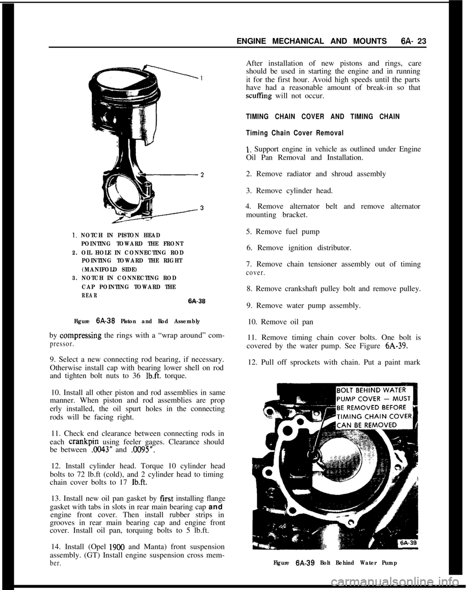
ENGINE MECHANICAL AND MOUNTS6A- 231. NOTCH IN PISTON HEAD
POINTING TOWARD THE FRONT
2. OIL HOLE IN CONNECTING ROD
POINTING TOWARD THE RIGHT
(MANIFOLD SIDE)
3. NOTCH IN CONNECTING ROD
CAP POINTING TOWARD THE
REAR6A-36
Figure
6A-39 Piston and Rod Assemblyby oompressing the rings with a “wrap around” com-
pressor.9. Select a new connecting rod bearing, if necessary.
Otherwise install cap with bearing lower shell on rod
and tighten bolt nuts to 36
lb.ft. torque.
10. Install all other piston and rod assemblies in same
manner. When piston and rod assemblies are prop
erly installed, the oil spurt holes in the connecting
rods will be facing right.
11. Check end clearance between connecting rods in
each crankpin using feeler gages. Clearance should
be between
.0043” and .0095”.
12. Install cylinder head. Torque 10 cylinder head
bolts to 72 lb.ft (cold), and 2 cylinder head to timing
chain cover bolts to 17
lb.ft.13. Install new oil pan gasket by first installing flange
gasket with tabs in slots in rear main bearing cap and
engine front cover. Then install rubber strips in
grooves in rear main bearing cap and engine front
cover. Install oil pan, torquing bolts to 5 lb.ft.
14. Install (Opel
1900 and Manta) front suspension
assembly. (GT) Install engine suspension cross mem-
ber.After installation of new pistons and rings, care
should be used in starting the engine and in running
it for the first hour. Avoid high speeds until the parts
have had a reasonable amount of break-in so that
scuffling will not occur.
TIMING CHAIN COVER AND TIMING CHAIN
Timing Chain Cover Removal
1, Support engine in vehicle as outlined under Engine
Oil Pan Removal and Installation.
2. Remove radiator and shroud assembly
3. Remove cylinder head.
4. Remove alternator belt and remove alternator
mounting bracket.
5. Remove fuel pump
6. Remove ignition distributor.
7. Remove chain tensioner assembly out of timing
cover.8. Remove crankshaft pulley bolt and remove pulley.
9. Remove water pump assembly.
10. Remove oil pan
11. Remove timing chain cover bolts. One bolt is
covered by the water pump. See Figure 6A-39.
12. Pull off sprockets with chain. Put a paint mark
Figure 6A-39 Bolt Behind Water Pump
Page 324 of 625
COOLING SYSTEM6B- 33
remove drain plug on right.side of cylinder block. Set
heater temperature control valve at full heat posi-
tion. After the cooling system is drained, and plugs
reinstalled, fill the system with clean water. Run the
engine long enough to open the thermostat for com-
plete circulation through the system, then com-
pletely drain the cooling system before sediment has
a chance to settle.
Conditioning the Cooling System
“Rust Inhibitor and Stop Leak”, or equivalent listed
under Group 8.800 is recommended for use in the
cooling system, particularly when preparing for in-
stallation of anti-freeze solution. This material stops
small seepage leaks, has rust preventive properties
and its soluble oil is effective in eliminating a squeal-
ing noise which sometimes develops at the water
pump seal washer. Instructions for its application are
printed on the conditioner bottle.
It is very important to make certain that the cooling
system is properly prepared before an anti-freeze so-
lution is installed, otherwise loss of solution through
leakage may occur or seepage may result in damage
to the engine. The cooling system should be drained
and flushed as described under Draining and Flush-
ing Cooling System. All joints should be checked for
leakage and corrected, and the conditioner described
above should be added with the anti-freeze solution.
Inspect the water pump, radiator core, heater and
defroster cores, water jacket plugs, and edge of cylin-
der head gaskets for evidence of water leaks. Tighten
all hose clamps in the cooling and heating systems
and replace any deteriorated hoses.
Using and Testing Anti-Freeze
Solutions
Inhibited year around (ethylene glycol type) engine
coolant solution which is formulated to withstand
two full calendar years of normal operation without
draining or adding inhibitors should be used at all
times. Freeze protection should be provided to pro-
tect against corrosion. When adding solution due to
loss of coolant for any reason or in areas where tem-
peratures lower than minus 20 degrees F. may be
encountered, a sufficient amount of any of the sev-
eral brands of year around coolant (Ethylene Glycol
base) compatible to GM Specification 1899-M avail-
able on the market should be used. Water or alcohol
base coolants are not recommended for this vehicle
at any time.
If for any reason water only is used as a coolant in
an emergency, it is extremely important that Buick
Heavy Duty Cooling System Protector and Water
Pump Lubricant or equivalent be added to the cool-
ing system as soon as possible. If any other cooling
System protector is used, be certain it is labeled toindicate that it meets General Motors Specification
GM 1894-M. It should be recognized that this is only
a temporary measure. The manufacture intends that
permanent type coolant solution be used year around
in the cooling system.
The cooling system should be completely drained
and the recommended coolant installed every two (2)years.It is advisable to test the anti-freeze solution at inter-
vals during the winter to make certain that the solu-
tion has not been weakened. Use only hydrometers
which are calibrated to read both the specific gravity
and the temperature, and have a table or other means
of converting the freezing point at various tempera-
tures of solution. Disregarding the temperature of
the solution when making the test may cause an error
as large as 30 degrees F. Care must be exercised to
use the correct float or table for the particular type
of anti-freeze being tested.
Fan Belt Adjustment or Replacement
A tight fan belt will cause rapid wear of the alterna-
tor and water pump bearings. A loose belt will slip
and wear excessively and will cause noise, engine
over-heating, and unsteady alternator output. A fan
belt which is cracked or frayed, or which is worn so
that it bottoms in the pulleys should be replaced. The
fan belt may be replaced by loosening the alternator
brace at alternator, slightly loosening the alternator
mounting bolts and moving alternator inward to pro-
vide maximum slack in the belt.
The alternator must be moved outward to adjust the
fan belt. After the generator brace and mounting
bolts are securely tightened, the fan belt tension
should be 45 lb. using Tensioner J-23600.
WARNING: Zfa
fan blade is bent or damaged in any
way, no attempt should be made to repair and reuse
the damaged part. A bent or damaged fan assembly
should always be replaced with a new
fal. assembly.
It is essential that fan assemblies remain in proper
balance and proper balance cannot be assured once
a fan assembly has been bent or damaged. A fan
assembly that is not in proper balance could fail and
fly apart during subsequent
we creating an ex-
tremely dangerous condition.
Radiator Thermostat Inspection and Test
A sticking radiator thermostat will prevent the cool-
ing system from functioning properly. If the thermo-
stat sticks in the open position, the engine will warm
up very slowly. If the thermostat sticks in the closed
position, the engine will overheat.
The thermostat may be removed for inspection and
Page 621 of 625
SubjectPage Number
Subject Page Number
A
Air Conditioning Refrigerant Components .................
98.17
Opel 1900
& Manta-In Car Components .....9B-90
GT.ln Car Components..................98-97
Alignment Opel 1900
& Manta .....................3C-22
GT-Opel ..............................
3C-22
Alternator Description ...........................
lD-28
Specifications. .........................1 D-35
Overhaul K-l..........................lD-30
Removal & Installation ..................lD-30
Testing...............................lD-29
Wiring Diagrams
Manta .............................
1 J-105
Opel 1900
..........................lJ-103
GT ................................
lJ-107
AM
Radio-GT............................9C-105
AM Radio-Opel 1900 &Manta ...............
9C-109
Antenna, Installation .......................
9C-111
Antenna Trimmer .........................
9C-110
Assembly of Transmission from Major Units Manual ...............................
78-23
3 Speed Automatic .....................
7C-103
Axle,
R&r, Disassembly ....................48~11
Bolt Torque Specifications
Engine ...............................
6A-27
Transmission. Manual ....................
78-33
3 Speed Automatic .....................
7C-136
Clutch ...............................
7A-7
Body ................................
2A-4
Brakes
Brake Drum, Shoes & Linings .............5C-28
Hydraulic Wheel Cylinder ................
5C-30
Hydraulic Master Cylinder ................
5A-2
Parking Brake Cables .....................
5C-33
Standard Brakes ........................
X-22
Disc Brakes...........................5B-10
Brake Booster and Vacuum
Coritrol Valve ....5A-5
Bumpers, Front and Rear ...................
ZH-33
C
B
Balance,,Wheel and Tire....................3G-62
Ball
J&tUpper .........................3A-7
Lower ...............................
3A-7
Battery
Specifications ..........................
lA-9
Testing...............................lA-6
Charging ..............................lA-9
Trouble Diagnosis ......................lA-4
Battery Test 421.........................l A-6
Belt Tensions ............................
68.33
Blower and Air Inlet Assembly, Removal and Installation
Owl 1900&Manta.....................9A-15
GT
.: ................................9A-5
Body Name Plate ............................
OA-1
Style’Numbers ......................... OA-2
Windows and Weatherstrips ...............
ZC-9
Doors ................................
ZD-13
Interior Trim and Headlining ..............
26-33
Seatsi................................26-33
Roof&d Sunroof-Opel 1900
& Manta ......2F.24 Camshaft,
1.9L
Engine .....................6A-25
Car Model Identification .......
.,............OA-1
Carburetor..............................6E-44
Trouble Diagnosis ......................
6E-49
Description ...........................
6E-44
Overhaul .............................
6E-53
Adjust ...............................
6E-50
Removal
& Installation ......,............6E-52
Specifications ..........................
6E-58
Charging
System
Description ..............
:............ 1 D-28
Specifications. ............
.,............lD-35
Testing..................:............lD-29
Wiring Diagrams
Manta .............................
lJ-105
Opel 1900 ..........................
lJ.103
GT ................................
lJ-107
Chart Lubrication ........................ OC-5
Chassis Springs, Front. ........
!............3A-15
Clutch, Second-Automatic Transmission .......
7C-103
Clutch Adjustment .........................
7A-4
Control Arm Front Upper ...................
:............3A-10
Lower ...............................
3A-11
Converter Checking Procedure ................
7C-125
Coolant Flow ............................
68-32
4 Speed Manual Transmission ...
!,...........7B-12
Cranking System. See Starting
SyStem
Crankshaft..............................6A-16
Cylinder Head ...............
:............6A-12
D
Description
3.Speed Automatic.....................7C-37