brake OPEL MANTA 1973 Service Manual
[x] Cancel search | Manufacturer: OPEL, Model Year: 1973, Model line: MANTA, Model: OPEL MANTA 1973Pages: 625, PDF Size: 17.22 MB
Page 4 of 625
1973
GTOPEL1900
MANTA
CHASSISSERVICE
MANUAL
This manual contains service informationfor the 1973 Opel 1900, Manta and GT
models. Refer to the introduction for
adescription of the arrangement of this
manual for locating desired information
easily.All
infotmation, illustrations and specifi-cations contained in this manual are basedon the latest product information aveil-able at the time of publication approval.
Therefore, the right is reserved to make
changes at any time without notice.TABLE OF CONTENTS
SUBJECT
I I
1ELECTRICAL
I I2FRAME AND BUMPERS
I I3SUSPENSION AND STEERING
I I4REAR AXLE
I I5BRAKES
I I
6ENGINE
I I7TRANSMISSION
I I
8CHASSIS SHEET METAL
I I
9ACCESSORIES
Page 5 of 625
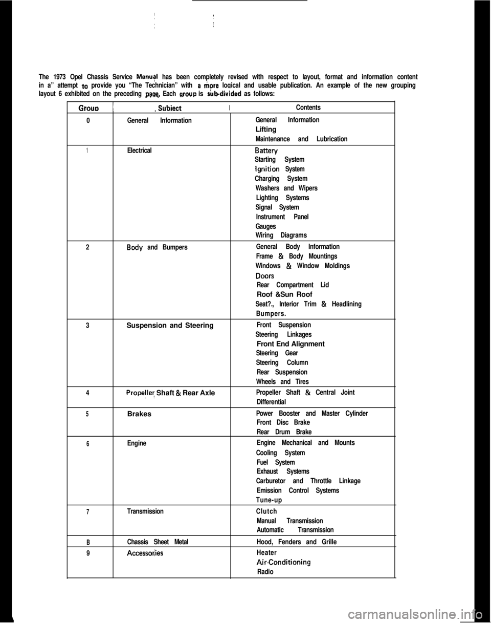
The 1973 Opel Chassis Service MayI has been completely revised with respect to layout, format and information content
in a” attempt
to provide you “The Technician” with a tiore logical and usable publication. An example of the new grouping
layout 6 exhibited on the preceding
page. Each wow is rubdivided as follows:
Grouo 1
_. _
Subiect IIContents.
0
General InformationIGeneral InformationLifting
Maintenance and Lubrication
1ElectricalBattery
Starting System
lgriition System
Charging System
Washers and Wipers
Lighting Systems
Signal SystemI
Instrument Panel
Gauges
Wiring Diagrams
2
Body and Bumpers:General Body InformationI
Frame & Body Mountings
Windows
& Window Moldings
DONS
Rear Compartment LidRoof &Sun Roof
Seat?., Interior Trim & Headlining
Bumpers.
3Suspension and Steering
Front Suspension
Steering Linkages1Front End Alignment
Steering Gear
Steering Column
Rear Suspension
Wheels and Tires
4
Propelley Shaft & Rear AxlePropeller Shaft & Central Joint
Differential
5Brakes ~Power Booster and Master Cylinder
Front Disc BrakeI
Rear Drum Brake
6EngineEngine Mechanical and Mounts
Cooling System
Fuel System
Exhaust Systems
Carburetor and Throttle Linkage
Emission Control Systems
Tune-up
7TransmissionClutch
Manual Transmission
Automatic Transmission
BChassis Sheet MetalHood, Fenders and Grille
9
Accessol;iesHeaterAirConditioning
Radio
Page 14 of 625
LUBRICATION AND MAINTENANCE OC-5LUBRICATION AND MAINTENANCE
LOEngine Oil ,current “ISCOI-ifVl SE’
-u9 Lubriplate’,9F Hvdraulic Brake Fluid -Delco supreme NO. 11’
CAPAClTlESOPEL 1900Coding SystemMANTA GT
,OW,6 6
UU
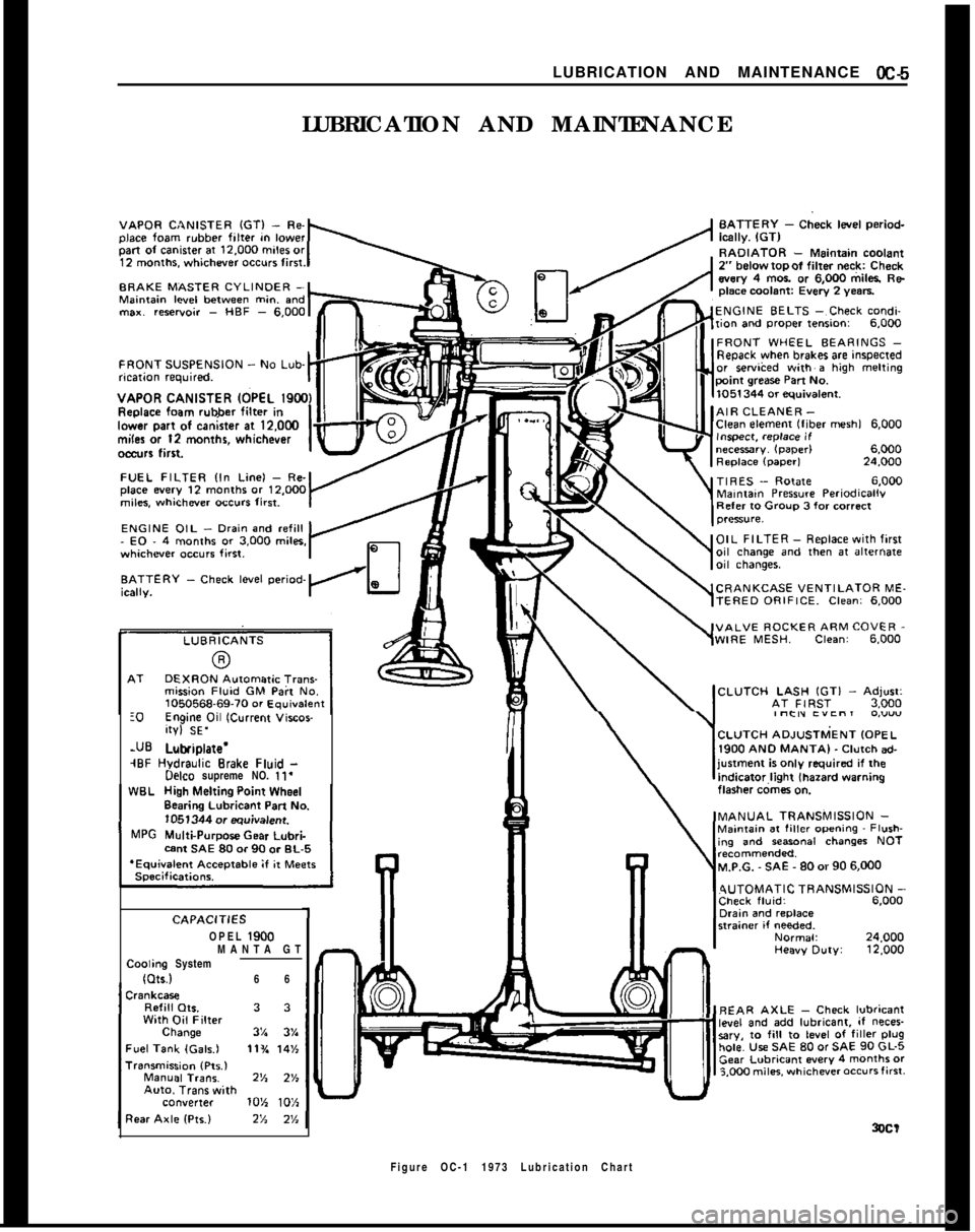
3oclFigure OC-1 1973 Lubrication Chart
Page 16 of 625
LUBRICATION AND MAINTENANCE OC-7SERVICESLUBE AND GENERAL MAINTENANCE
Vehicle operation under conditions such as heavy
dust, continuous short trips, use of other than un-
leaded or low lead fuels or pulling trailers, is not
considered normal use and therefore more frequent
maintenance will be required. Such additional
maintenance requirements are included where appli-
cable.
Engine OilChange each 4 months or
3,COO miles, whichever
occurs first, or each 2 months or
3,ooO miles when
the vehicle is operated under the following condi-
tions: (a) driving in dusty conditions, (b) trailer pull-
ing, (c) extensive idling or (d) short-trip operation at
freezing temperatures (with engine not thoroughly
warmed-up).Engine oils have a definite effect on ease of starting,
oil economy, combustion chamber deposits and en-
gine wear. It is recommended that a” oil which,
according to the label on the can is; (1) intended for
service SE and (2) passes car makers’ tests be used.
Oils confotming to these types contain detergent ad-
ditives. -
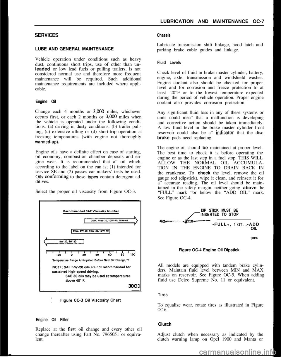
Select the proper oil viscosity from Figure OC-3.
Engine Oil FilterReplace at the first oil change and every other oil
change thereafter using Part No. 7965051 or equiva-
lent.
ChassisLubricate transmission shift linkage, hood latch and
parking brake cable guides and linkage.
Fluid LevelsCheck level of fluid in brake master cylinder, battery,
engine, axle, transmission and windshield washer.
Engine coolant also should be checked for proper
level and for corrosion and freeze protection to at
least -20°F or to the lowest temperature expected
during the period of vehicle operation. Proper engine
coolant also provides corrosion protection.
Any significant fluid loss in any of these systems or
units could mea” that a malfunction is developing
and corrective action should be taken immediately.
A low fluid level in the brake master cylinder front
reservoir could also be a” indtcator that the disc
brake pads need replacing.
The engine oil should be maintained at proper level.
The best time to check it is before operating the
engine or as the last step in a fuel stop. THIS WILL
ALLOW THE NORMAL OIL ACCUMULA-
TION IN THE ENGINE TO DRAIN BACK IN
the crankcase. To check the level, remove the oil
gauge rod (dipstick), wipe it clean, and reinsert it for
a” accurate reading. The oil level should be main-
tained in the safety margin, neither going above the
“FULL” mark “or below the “ADD OIL” mark.
See Figure OC-4.
DIP STICK MUST BE
INSERTED TO STOP
---L- -FULL+, 1 OT. ,-ADD
OIL
Figure OC-4 Engine Oil Dipstick
All models are equipped with tandem brake cylin-
ders. Maintain fluid level between MIN and MAX
marks on reservoir. See Figure OC-5. When adding
fluid use Delco Supreme No. 11 or equivalent.
TiresTo equalize wear, rotate tires as illustrated in Figure
OC-6.Adjust clutch when necessary as indicated by the
clutch warning lamp on Opel 1900 and Manta or
Page 17 of 625
IoC-91973 OPEL SERVICE MANUAL
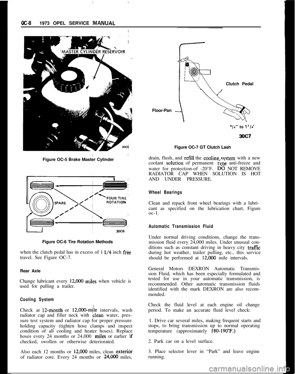
Figure OC-5 Brake Master Cylinder
I
Figure OC-6 Tire Rotation Methods
when the clutch pedal has in excess of 1
l/4 inch fr&
travel. See Figure OC-7.
Rear Axle
Change lubricant every
12,ooO miies when vehicle is
used for pulling a trailer.
Cooling SystemCheck at 12-month or
12,000~mile intervals, wash
radiator cap and filler neck with clean water, pres-
sure test system and radiator cap for proper pressure
holding capacity (tighten hose clamps and inspect
condition of all cooling and heater hoses). Replace
hoses every 24 months or 24,000 ,miles or earlier :if
checked, swollen or otherwise deteriorated.
Also each 12 months or
12,ooO miles, clean exteribr
of radiator core. Every 24 months or
24,OCO miles,Floor-Pan
-Clutch Pedal
Figure OC-7 GT Clutch Lash
drain, flush, and refill the cooline svstem with a new
coolant so&ion of permanent
6~; anti-freeze and
water for protection-of -20°F.
D-6 NOT REMOVE
RADIATOR CAP WHEN SOLUTION IS HOT
AND UNDER PRESSURE.
Wheel BearingsClean and repack front wheel bearings with a lubri-
cant as specified on the lubrication chart, Figure
oc-1.
Automatic Transmission FluidUnder normal driving conditions, change the trans-
mission fluid every 24,000 miles. Under unusual con-
ditions such as constant driving in heavy city traffic
during hot weather, trailer pulling, etc., this service
should be performed at
12,COO mile intervals.
General Motors DEXRON Automatic Transmis-
sion Fluid, which has been especially formulated and
tested for use in your automatic transmission, is
recommended. Other automatic transmission fluids
identified with the mark DEXRON are also recom-
mended.
Check the fluid level at each engine oil change
period. To make an accurate fluid level check:
1. Drive car several miles, making frequent starts and
stops, to bring transmission up to normal operating
temperature (approximately
180-190’F.)2. Park car on a level surface.
3. Place selector lever in “Park” and leave engine
running.
Page 18 of 625
LUBRICATION AND MAINTENANCE OC-9
4. Remove dipstick and wipe clean.
5. Reinsert dipstick untip cap seats.
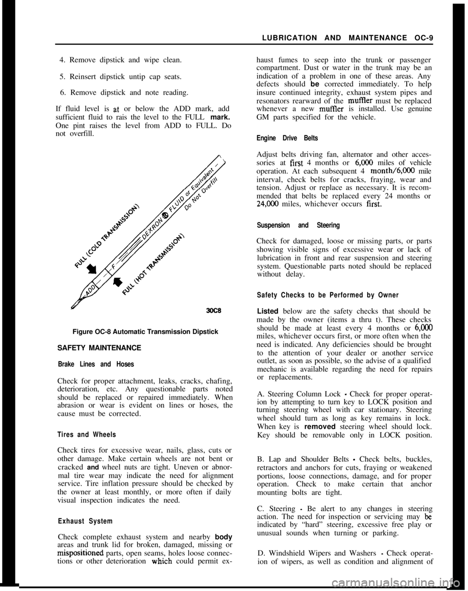
6. Remove dipstick and note reading.
If fluid level is at, or below the ADD mark, add
sufficient fluid to rais the level to the FULL mark.
One pint raises the level from ADD to FULL. Do
not overfill.
3OC8Figure OC-8 Automatic Transmission Dipstick
SAFETY MAINTENANCE
Brake Lines and HosesCheck for proper attachment, leaks, cracks, chafing,
deterioration, etc. Any questionable parts noted
should be replaced or repaired immediately. When
abrasion or wear is evident on lines or hoses, the
cause must be corrected.
Tires and WheelsCheck tires for excessive wear, nails, glass, cuts or
other damage. Make certain wheels are not bent or
cracked and wheel nuts are tight. Uneven or abnor-
mal tire wear may indicate the need for alignment
service. Tire inflation pressure should be checked by
the owner at least monthly, or more often if daily
visual inspection indicates the need.
Exhaust SystemCheck complete exhaust system and nearby body
areas and trunk lid for broken, damaged, missing orm&positioned parts, open seams, holes loose connec-
tions or other deterioration wiuch could permit ex-haust fumes to seep into the trunk or passenger
compartment. Dust or water in the trunk may be an
indication of a problem in one of these areas. Any
defects should be corrected immediately. To help
insure continued integrity, exhaust system pipes and
resonators rearward of the muftler must be replaced
whenever a new mufIler is installed. Use genuine
GM parts specified for the vehicle.
Engine Drive BeltsAdjust belts driving fan, alternator and other acces-
sories at first 4 months or
6,ooO miles of vehicle
operation. At each subsequent 4 month/6,000 mile
interval, check belts for cracks, fraying, wear and
tension. Adjust or replace as necessary. It is recom-
mended that belts be replaced every 24 months or
24,C00 miles, whichever occurs first.
Suspension and SteeringCheck for damaged, loose or missing parts, or parts
showing visible signs of excessive wear or lack of
lubrication in front and rear suspension and steering
system. Questionable parts noted should be replaced
without delay.
Safety Checks to be Performed by OwnerListed below are the safety checks that should be
made by the owner (items a thru t). These checks
should be made at least every 4 months or
6,ooOmiles, whichever occurs first, or more often when the
need is indicated. Any deficiencies should be brought
to the attention of your dealer or another service
outlet, as soon as possible, so the advise of a qualified
mechanic is available regarding the need for repairs
or replacements.
A. Steering Column Lock
_ Check for proper operat-
ion by attempting to turn key to LOCK position and
turning steering wheel with car stationary. Steering
wheel should turn as long as key remains in lock.
When key is removed steering wheel should lock.
Key should be removable only in LOCK position.
B. Lap and Shoulder Belts
- Check belts, buckles,
retractors and anchors for cuts, fraying or weakened
portions, loose connections, damage, and for proper
operation. Check to make certain that anchor
mounting bolts are tight.
C. Steering
- Be alert to any changes in steering
action. The need for inspection or servicing may
beindicated by “hard” steering, excessive free play or
unusual sounds when turning or parking.
D. Windshield Wipers and Washers
- Check operat-
ion of wipers, as well as condition and alignment of
Page 19 of 625
CC-10 1973 OPEL SERVICE MANUAL
wiper blades. Check amount and direction of fluid
sprayed by washers during use.,
E. Defrosters - Check performance by moving con-
trols to “DEF” and noting
am$nmt of air directed
against the windshield.
I
F. Wheel Alignment and
Balabce - In addition to
abnormal tire wear, the need fbr wheel alignment
service may be indicated by a pull to the right or
!eftwhen driving on a straight and level road. The need
for wheel balancing is usually
iddicated by a vibra-
tion of the steering wheel or
se;+ tihile driving at
normal highway speeds.I
IG. Brakes
- Be alert to illumiriation of the brake
warning light or changes in braking action,
SUCK as
repeated pulling to one side, unusual sounds when
braking or increased brake pedal travel. Any of thesecould indicate the need for
brakk system inspection
and/or service.
H. Parking Brake and Transmission “PARK”
Mechanism
- Check parking brake holding ability by
parking on a fairly steep hill and restraining the vehi-
cle with the parking brake only.
eon cars with auto-
matic transmissions, check the holding ability of the
“PARK” mechanism by releasing all brakes after
the transmission selector lever hak been placed in the“P” position.
I. Glass
- Check for broken, scrritched, dirty or da-
maged glass on vehicle that
coulld obscure vision’or
become an injury hazard.
J. Lights and Buzzers
- Check all instrument panel
illuminating and warning lights,’ seat belt reminder
light and buzzer, ignition key
b&er, interior lights,
license plate lights, side marker! lights, headlamps,
parking lamps, tail lamps, brake lights, turn signals,
backup lamps, and hazard warding flashers. Have
someone observe operation of
&ach exterior light
while you activate the controls: The operation of
instrument panel warning lights is covered in the
“Starting and Operating“ section of your
Own&%
Manual.K. Transmission Shift Indicator
‘- Check to be sure
automatic transmission shift
indiCator accurately i”-
dicates the shift position selected.
I
CAUTION: Before making thk check below,I
be sure to have a clear dist&e ahead and:
behind the car, set the parking brake and
firmly apply the foot brake.
Do not depress
accelerator pedal. Be prepared to
turn off ’
ignition switch
immediat+y if engine
should start.L. Starter Safety Switch (Automatic Transmissibn
Cars)
- Check starter safety switch by placing the
transmission in each of the driving gears while
at-tempting to start the engine. The starter should oper-ate only in the Park (“P”) or Neutral (“N”)
positions.
M. Horn
- Blow the horn occasionally to be sure thatit works. (Ignition switch must be in the “ON” posi-
tion.)
N. Seat Back Latches
- Check to see that seat back
latches are holding by pulling forward on the top of
each folding seat back.
0. Rearview Mirrors and Sun Visors
- Check that
friction joints are properly adjusted so mirrors and
sun visors stay in the selected position.
P. Door Latches
- Check for positive closing, latch-
ing and locking.
Q. Hood Latches - Check to make sure hood closesfirmly by pressing on the hood at the latching point
after each closing. Check also for broken, damaged
or missing parts which might prevent secure latch-
ing.R. Fluid Leaks
- Check for fuel, water, oil or other
fluid leaks by observing the ground beneath the vehi-cle after it has been parked for a while. If gasoline
fumes or fluid are noticed at any time, the cause
should be determined and corrected without delay
because of the possibility of fire.
S. Exhaust System
- Be alert to any change in the
sound of the exhaust system or a smell of fumes
which may indicate a leak.
Head Restraints
- Check that no head restraint
components are missing, damaged or loose. (Does
not apply to GT Models).
Disc BrakesCheck brake pads and condition of rotors while
wheels are removed during tire rotation. (Note belowregarding more frequent checks also applies to disc
brakes.)
Parking and Drum BrakesCheck drum
brake linings and other internal brake
components at each wheel (drums, wheel cylinders,
etc.). Parking brake adjustment also should be
checked whenever drum brake linings are checked.
NOTE: More frequent checks should be
made if driving conditions a.nd habits result
in frequent brake application. When brakes
require relining, it is recommended thatyou use those genuine General Motors
parts specified for your car,and Delco fluid
as required.
Page 33 of 625
19- 12 1973 OPEL SERVICE MANUAL :ConditionPosiible CauseCorrection4. Voltage drop.1. Check wiring and wiring
connections.
5. Overrun&g clutch slips.1. Replace overrunning clutch.
The cranking motor keeps
on rotating after ignition
switch is off.1. Ignition
{witch does not
cut off or solenoid switch
sticks.
1, Immediately disconnect cranking
motor cable from battery. Inspect
and/or replace or repair ignition and
solenoid switches as required.
The drive pinion does notdemesh after engine has
been cranked.1. Drive pinion or ring gear
1. Clean components as specified.
teeth clogged or flattened.Replace as required.
Return spring slack or broken.MAlNTEilANCE AND ADJUSTMENT
/
STARTING SYSTEM CHECKS
Voltage Loss ChecksWhen the starter cranks too slowly, check the bat-
tery state of charge and all electrical connections
between the battery and starter.
1. Turn on headlights and
opera’te starter. If head-
lights dim considerably when starter is engaged, the
battery may be discharged or be defective. Check the
battery.
2. If the headlights stay bright but the starter d&s
not turn over, the starter cables may be faulty or the
starter defective.
(a) Test battery voltage while cranking engine
1(9volts minimum).
(b) Check voltage from starter tkrminal of solenoid
to starter frame while cranking engine.
3. The difference in readings taken in Operations 2a
and 2b above represents the
volt& drop through the
cables and solenoid switch. Voltdge drop should
Gotexceed
.5 volt.
4. Locate excessive resistance as follows:
(a) Turn voltmeter to scale above 12 volts and con-
nect voltmeter leads
across connection or switch: to
be checked.
(b) With starter switch closed, turn voltmeter switch
to lowest scale and take reading as quickly as possi-
ble, then turn switch back to higher scale and stop
cranking engine.(c) Voltmeter must not read more than
.2 volt across
any
c:onnection. If voltmeter reads more than .2 volt,
the
d~efect must be corrected.
Starter Current Draw - Lock Test1. Make sure battery is fully charged and in good
condition.
2. Connect a volt ampere starter tester according to
manufacturer’s instructions.
3. Pull parking brake on securely, shift transmission
into 4th (direct) gear and actuate starter. (Starter will
not
t,urn engine because engine is locked through
transmission.)
4. While starter is actuated, read voltage and current.
Refer to Specification Chart.
(a) Voltage low
_ poor battery or a voltage loss in the
starter circuit.
(b) Current high
- short circuit in starter. Overhaul
starter.
(c) Current low
- commutator dirty, brushes worn,
solenoid switch contacts defective or open circuit in
starter. Overhaul starter.
Starter Current Draw. On Car1. Bring engine to normal operating temperature.
2. Stop engine and disconnect coil wire from dis-
tributor.
3. Ground coil wire to prevent excessive coil voltage
build up.
Page 75 of 625
lG- 54 1973 OPEL SERVICE’ MANtiAL/SIGNAL SYSTEMSCdNTENTS
9Subject
DESCRIPTION AND OPERAT!ON:
Directional Signal Lever
. . . . . . . . . . . . . . . . . . . . . . . . . . . . . . . . . . . . . . . . . . . . . . . . . .
Horn. . . . . . . . . . . . . . . . . . . . . . . . . . . . . . . . . . . . . . . . . . . . . . . . . . . . . . . . . . . . . . . . . . . . . . . . . . . . . . . . . . . . . . . .HazardWarning
Flasher. . . . . . . . . . . . . . . . . . . . . . . . . . . . . . . . . . . . . . . . . . . . . . . .BrakeSystemWarningLight
. . . . . . . . . . . . . . . . . . . . . . . . . . . . . . . . . . . . . . . .DIAGNOSIS:
SignalSystem,.......................
i . . . . . . . . . . . . . . . . . . . . . . . . . . . . . . . . . . . . . . . . . . . . .MAINTENANCE AND ADJUS,TMENTS:
MAJOR REPAIR:
Directional Signal Switch
:. . . . . . . . . . . . . . . . . . . . . . . . . . . . . . . . . . . . . . . . . . . . .
HornRemoval. . . . . . . . . . . . . . . . . . . . . . . . . . . . . . . . . . . . . . . . . . . . . . . . . . . . . . . . . . . . . . . . . . . . . .Removing Horn Contact
. . . . :.............................................
SPECIFICATIONS:
FuseChart. . . . . . I . . . . . . . . . . . . . . . . . . . . . . . . . . . . . . . . . . . . . . . . . . . . . . . . . . . . . . . . . . . . . . . . . . . . .Page No.
1 G-54
1 G-54
1 G-55
lG-55 _1 G-55
1 G-55
16-551 G-55
1 G-56
DESCRIPTION AND OPERATION
DIRECTIONAL SIGNAL LEVERThe direction signal switch lever is a multi- purpose
lever controlling direction signals, passing signal,
and high and low beams. See Figure
lG-1.301Gl
Figure lG-1 Directional Signal Position for Headlamp
OperationThe direction signal lever is provided with a
two-step mechanism for operation of headlight high and
low beams, and passing signal (not in New Jersey).
With headlights off, moving the lever repeatedly to-
wards steering wheel flashes headlights as a passing
signal. With headlights on, moving the lever repeat-
edly towards steering wheel up to first stop also
flashes passing signal regardless whether or not the
direcl:ion signals are switched on. When the lever is
moved up to the second stop, the headlights are
changed from high to low beam
dr vice versa. On all
Rallye cars, when switching from low to high beam
position, with the fog lamp instrument panel switch
“ON” and ignition switch in “RUN” position, the
fog lights are automatically
switChed off. Direction
signals work in the normal manner; pushing the lever
up for right turn signal and pulling the lever down
for left turn signal.
The horn button is located in the center part of the
steering wheel. The horn is actuated by pushing
down on the ends of both spokes on Opel 1900 andManta’s or on the center horn button on the Rallye.
The button is provided with a spring-loaded plunger.See Figure
lG-2.
Page 76 of 625
Tigure lG-2 Horn Button and Contact
HAZARD; WARNING FLASHER
The hazard warning flasher is operated by the button
on the
toi, of the steering column. When the button
is
press&@ down and released, all four turn signal
lights
WIU flash. To turn the flasher system off, press
down
oni the button and release. When the hazard
warning
hystem is operating, a flashing light in the
iristrumeht cluster will operate. The hazard warning
flasher
&itch is part of the directional signal switch.
BRAKE $YSTEM WARNING LIGHT
The brak; system warning light is located in the left
side of
tpe instrument cluster assembly. The light
will
come on when the brake pedal is depressed and
the ignition is on if there is a hydraulic leak in the
brake system. The light will go out when the foot is
removed!from the brake pedal. The light will also
glow with the parking brake applied and the ignition
on. (On
Iautomatic transmission equipped vehicles,
light is
a! reminder to release parking brake; and on
manual
fransmission equipped vehicles, light glows
when
the clutch pedal needs adjustment,)
I
DlAGNfXlS
SIGNAL SYSTEM
The indiLator light on the dash will show defects in
the directional signal system as follows:
1.
Indic
tie switched-on directional signal lamp bulbs
is defective. The other signal lamp will continue to
flash.
Thi most common defect is a burned out bulb.
2.
Indicdtor light on dash stays on when directional
signal
leier is switched to either side. Check flasher
unit. I
SIGNAL SYSTEMSlG- 55
MAJOR REPAIR
Removing and Installing Directional Signal Switch
Proceed as outlined in Group 3, Section E.
HORN REMOVAL
1. Remove grille (GT only).
2. Remove horn bracket attaching bolt.
3. Disconnect wires and remove horn.
Installation
1. Install horn with bracket attaching bolt.
2. Connect horn wire.
3. Install grille (GT only).
Removing Horn Contact
1. Disconnect battery.
2. Remove horn cap.
3. Bend lockplate tabs down and remove steering
wheel nut, lockplate, and washer.
4. Mark shaft and wheel hub for reassembly align-
ment.
5. Remove steering wheel using Wheel Puller
J-
21686.
6. Remove horn contact from wheel.
installation
1. Replace horn contact.
2. Before installing steering wheel, lubricate return
pin and slide area on directional signal switch return
cams and contact ring.
3. With steering wheel properly aligned to shaft, in-
stall washer, lockplate, and nut. Torque nut to 15
lb.ft.
4. Bend up lockplate tab and install horn cap.
5. Connect battery.