fuel pressure OPEL MANTA 1973 Service Manual
[x] Cancel search | Manufacturer: OPEL, Model Year: 1973, Model line: MANTA, Model: OPEL MANTA 1973Pages: 625, PDF Size: 17.22 MB
Page 21 of 625
!
OC-12 1973 OPEL SERVICE MANUAL iExhaust Gas Recirculation Systep
Check system operation at 12 &onth/12,000 mile
intervals. Clean valve and EGR &usages if required;
A valve with a damaged diaphragm must be re-
placed.I
Engine CompressionTest engine cranking compressi& If a problem
exists, correct it Minimum compression recorded;
many one cylinder should not be less that 70% ‘of
highest cylinder. For example, if fhe highest presstire
in any one cylinder is 150 pounds, the lowest
alloka-ble pressure for any other cylinder would be
l-05pounds (150
x 70% = 105).~
Fuel Cap, Fuel Lines and Fuel TankInspect the fuel tank, cap and lines for damage which
could cause leakage. Inspect fuel cap for correct seal-
ing ability and indications of physical damage. Re-
place any damaged or malfunctionining parts.
Air Cleaner ElementReplace the engine air cleaner element under normal
operating conditions every 24,000 miles. Operation
of vehicle in dusty areas will necessitate more fre-
quent element replacement.
CAUTION: Do not operate the engine with-
out the air cleaner unless temporary re-
moval is necessary during repair or
maintenance of the vehicle. When the aircIeaner is removed, backfiring can cause
fire in the engine compartment.
Page 67 of 625
1F. 46 1973 OPEL SERVICE MANUAL
’
/
Headlight High-Low Beam Control and Passing:
SignalI
When the headlights have been switched on, high
and low beam selection is made by raising the direc-
tional signal lever toward steering wheel. Each
ti&the lever is raised, beam position, will change.
When the headlights are not on, a flashing headlight
signal may be given by raising and lotiering the di-
rectional signal lever. With the headlights on and
inlow beam position, raising and lowering the direc-
tional signal lever will also cause the headlights to
flash.
Fog Light SwitchAll Rallye models are equipped with two white f?g
lights mounted below the front bumper.
The fog light toggle switch is located on the
insty-ment cluster to the left of the temperature and
fuelgauge cluster.
/
The fog lights can be turned off at any time by the
toggle switch, but can only be tyrned on when: :
1. The ignition switch on or the
?gine running.!
2. The fog light toggle switch lower half is pushed
in.3. The parking lights and/or low beam headlights
are
OKThe fog lights are automatically turned off if the
ignition switch is on and the headlights are switched
to high beam position.
Courtesy LightThe courtesy light illuminates the interior of the Car
when any door is opened. The courtesy light can also
be turned on with all doors closed by tilting the l&s.
GT Headlamp MechanismThe concealed headlamps are moved mechanically.
Pushing actuating lever on left side of console opens
headlamps and pulling lever closes headlamps. Two
(2) meshing gear segments convert the movement, of
the lever to a rotation of 180 degrees. The pivots of
the headlamps lie below the centerline so that with
headlamps in closed position, the headlamp housing
is flush with front sheet metal. Refer to Group 110,
Section “F”, for service procedures on the GT head-
lamp mechanism.
A white indicator lamp in the instrument panel lights
if the headlamps are not completely opened lorclosed The switches of the headlamp electrical sys-
tem are located behind the left headlamp operating,
mechanism.
MAINTENANCE AND ADJUSTMENTSHEADLAMP AIMING
The headlamps must be properly aimed in order to
obtain maximum road illumination and safety that
has been built into the headlighting equipment. With
the Guide T-3 type sealed beam units, proper aiming
is even more important because the increased range
and power of this lamp make even slight variations
from recommended aiming hazardous to approach-
ing motorists. The headlamps must be checked for
proper aim whenever a sealed beam unit is replaced
and after an adjustment or repairs of the front end
sheet metal assembly.
Regardless of method used for checking headlamp
aim, car must be at normal weight, that is, with gas,
oil, water, and spare tire. Tires must be uniformly
inflated to specified pressure. If car will regularly
carry an unusual load in rear compartment, or a
trailer, these loads should be on car when headlamps
are checked. Some States have special requirements
for headlamp aiming adjustment, and these require-
ments should be known and observed.
Horizontal and vertical aiming of each seal beam
unit is provided by two adjusting screws which move
the mounting ring in the body against the tension of
the coil spring. There is no adjustment for focus,
since the sealed beam unit is set for proper focus
during manufacturing assembly.
MAJOR REPAIRHEADLIGHT SWITCH
- OPEL 1900. MANTA
Removal1. Remove instrument cluster cover panel. See Sec-
tion H.
2. Compress retaining springs and pull switch out.
See Figure 1 F-
1.3. Pull multiple socket off switch.
Installation
1: Plug multiple socket in switch and push switch in
panel until clips lock in place.
2. Replace instrument cover and secure with two (2)
screws.
Page 77 of 625
:lG- 56 1973 OPEL SERVICE MANUAL
I
FUSEqOSlTlON
1
2
3
4
5
6AMPS.
5
5
8
15
15
8ClRClJlT$ PROTECTED
OPEL 1900
& ‘MANTA (51,53,54,57,57R)
LEFT PARkING LIGHT,
LEFTTAIL LIGHT, LEFTSIDE
MARKER LIGHTS
RIGHT PApKING LIGHT, RIGH TAIL LIGHT, RIGHT
SIDE MARKER LIGHTS, INSTRUMENT PANEL LIGHTS,
SHIFT GUADRANT LIGHTS, LICENSE PLATE LIGHT,
FOG LIGHTS (RALLYE ONLY)
IGNITION IKEY
WARNIN BUZZER, TRUNK LIGHT,
HAZARD WARNING FLA,SHER, COURTESY LIGHT, CLOCK
BACKUP L’IGHTS, BLOWER MOTOR, CIGAR LIGHTER; RADIO,
SAFETY BELT WARNING BUZZER AND LIGHT
WINDSHIELD WIPERS, WINDSHIELD WASHER (RALLYE
ONLY), HORN
STOP LIGtiTS,TURN
SlGsNAL AND INDICATOR LIGHT,
PARKING BRAKE WARNING AND BRAKE FAILURE LIGHT,
FUEL GAGE, TEMPERATURE GAGE, OIL PRESSUREINDICATGR LIGHT. CHARGING INDICATOR~LIGHT,
TACHOMETER AND OIL PRESSURE GAGE (RALLYE ONLY)
AIR CONDITIONING
- 20 AMP INLINE F:USE
8
5
16
5OPEL GT
(77)WINDSHIELD WIPERS, WINDSHIELD WASHER, HORN, BACKUP
LIGHT, SP;FETY BELT WARNING BUZZER AND LIGHT
STOP LIGHTS, TURN SIGNAL AND INDICATOR LIGHT,
PARKING BRAKE WARNING LIGHT (AUTOMATIC ONLY),
BRAKE FAILURE WARNING LIGHT, RADIO, TACHOMETER,
OIL PRESiURE GAGE
& INDICATOR LIGHT, FUEL GAGE,
TEMPERATURE GAGE, CHARGING INDICATOR LIGHT
CIGAR LIGHTER, BLOWER MOTORIGNITION~KEY WARNING BUZZER, COURTESY LIGHT, CLOCK,
HAZARD WARNING FLASHER
LEFT PARKING LIGHTS, LEFT TAIL LIGHT, LEFT REAR
SIDE MAdKER LIGHT
RIGHT PA’RKING LIGHTS, RIGHT TAIL LIGHT, RIGHT REAR
SIDE MAdKER LIGHT
INSTRUMENT PANEL LIGHTS, LICENSE PLATE LIGHT.
SHIFT QUADRANT LIGHT
AIR CON,DlTlONlNG
-A/C HAS A 20 AMP INLINE FUSE AND IS
CONNECTED TO THE HOTSIDE OF FUSE NO. 23OlG3
Page 86 of 625
GAUGES
CONTENTS
Subject
DESCRIPTION AND OPERATION:
DIAGNOSIS:
Temperature and Fuel Gauge
System-Opel1900-Manta. . . . . . . . . . . . . . . . . . . . . . . . . . . . . . . . . . . . . . . . . .
FuelGauge-GT. . . . . . . . . . . . . . . . . . . . . . . . . . . . . . . . . . . . . . . . . . . . . . . . . . . . . . . . . . . . . . . . . .MAINTENANCE AND ADJUSTMENTS:
MAJOR REPAIR:
Opel 1900
- Manta
Voltage Stabilizer
. . . . . . . . . . . . . . . . . . . . . . . . . . . . . . . . . . . . . . . . . . . . . . . . . . . . . . . .Speedometer
. . . . . . . . . . . . . . . . . . . . . . . . . . . . . . . . . . . . . . . . . . . . . . . . . . . . . . . . . . . . . . . . . . . .Electric
ClockorTachometer. . . . . . . . . . . . . . . . . . . . . . . . . . . . . . . . . . . .Temperature Indicator or Fuel Gauge
. . . . . . . . . . . . . . . . . . . .Rallye
Gauges. . . . . . . . . . . . . . . . . . . . . . . . . . . . . . . . . . . . . . . . . . . . . . . . . . . . . . . . . . . . . . . . . .Temperature
SendingUnit. . . . . . . . . . . . . . . . . . . . . . . . . . . . . . . . . . . . . . . . . .Oil Pressure Sending Unit
. . . . . . . . . . . . . . . . . . . . . . . . . . . . . . . . . . . . . . . . . .GT
Speedometer
. . . . . . . . . . . . . . . . . . . . . . . . . . . . . . . . . . . . . . . . . . . . . . . . . . . . . . . . . . . . . . . . . . . .Tachometer
. . . . . . . . . . . . . . . . . . . . . . . . . . . . . . . . . . . . . . . . . . . . . . . . . . . . . . . . . . . . . . . . . . . . . .Temperature Indicator and Fuel Gauge Dash, Unit
Electric
Clock. . . . . . . . . . . . . . . . . . . . . . . . . . . . . . . . . . . . . . . . . . . . . . . . . . . . . . . . . . . . . . . . . .Ammeter
andOilPressureGauge. . . . . . . . . . . . . . . . . . . . . . . . . . . .SPECIFICATIONS:
DIAGNOSISITEM(ERATURE
& FUEL GAUGE - SYSTEM
DIAGNOSIS (OPEL 1900, MANTA)
/
ConditionPossible Cause
I
Page No.
1l-65
1l-67
1l-67
1l-68
1l-68
1l-69
1l-69
1l-69
1l-70
1l-70
1l-70
1l-70
1l-71
1l-71
Correction
Temperature and gas gaugeinopetative1. Blown fuse1. Replace fuse. If new fuse
blows, repair short.
2. Defective voltage
stabilizer1. Install 40 ohm resistors
between ground
& connectors
(disconnect from units)
of temperature sending imit
and gas gauge tank unit. If
both dash units do not move
to full scale (tolerance
-one pointer width of either
side of full scale reading)
and the distance of movement
on the scale is the same,,
replace the voltage stabdner.
Page 91 of 625
lb 70 1973 OPEL SERVlCE!MANUAL
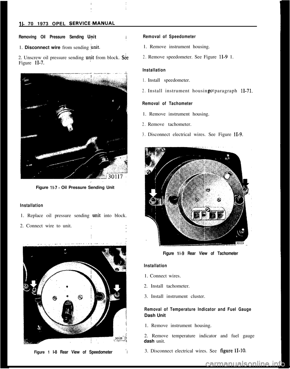
Removing Oil Pressure Sending Upit1. Disconnect wire from sending
Fit.2. Unscrew oil pressure sending
u?it from block. St&Figure
11-7./
Figure
11.7 - Oil Pressure Sending Unit
Installation1. Replace oil pressure sending unit into block.
2. Connect wire to unit.
Figure 1 l-8 Rear View of SpeedometerI
Removal of Speedometer1. Remove instrument housing.
2.Remove speedometer. See Figure 11-9 1.
Installation
1.Install speedometer.
2.Install instrument housing, paragraph 11-71.per
Removal of Tachometer1. Remove instrument housing.
2.Remove tachometer.
3.Disconnect electrical wires. See Figure 11-9.
Figure
11-9 Rear View of Tachometer
Installation1. Connect wires.
2. Install tachometer.
3. Install instrument cluster.
Removal of Temperature Indicator and Fuel GaugeDash Unit
1. Remove instrument housing.
2. Remove temperature indicator and fuel gauge
dash unit.
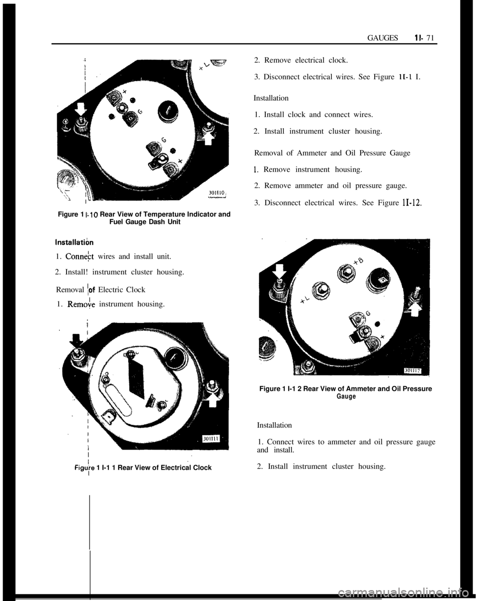
3. Disconnect electrical wires. See figure
11-10.
Page 92 of 625
I
IGAUGESll- 71
Figure 1
IL10 Rear View of Temperature Indicator and
I
IFuel Gauge Dash Unit
I
Install&m1. Connekt wires and install unit.
2. Install! instrument cluster housing.
I
Removal
\of Electric Clock
1.
Remoie instrument housing.
Figuy 1 I-1 1 Rear View of Electrical Clock
I2. Remove electrical clock.
3. Disconnect electrical wires. See Figure
11-I I.
Installation
1. Install clock and connect wires.
2. Install instrument cluster housing.
Removal of Ammeter and Oil Pressure Gauge
1. Remove instrument housing.
2. Remove ammeter and oil pressure gauge.
3. Disconnect electrical wires. See Figure
11-12.Figure 1 I-1 2 Rear View of Ammeter and Oil Pressure
GaugeInstallation
1. Connect wires to ammeter and oil pressure gauge
and install.
2. Install instrument cluster housing.
Page 295 of 625
6A. 41973 OPEL SERVICE MANUAL
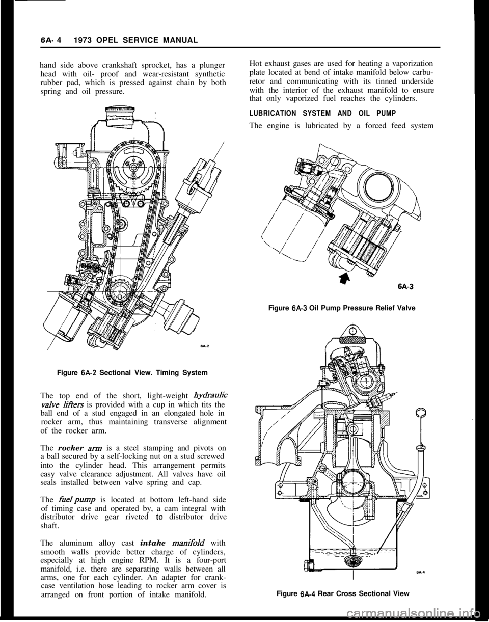
hand side above crankshaft sprocket, has a plunger
head with oil- proof and wear-resistant synthetic
rubber pad, which is pressed against chain by both
spring and oil pressure.
Figure 6A-2 Sectional View. Timing System
The top end of the short, light-weight hydrauricvalve
liffers is provided with a cup in which tits the
ball end of a stud engaged in an elongated hole in
rocker arm, thus maintaining transverse alignment
of the rocker arm.
The rocker
xrn is a steel stamping and pivots on
a ball secured by a self-locking nut on a stud screwed
into the cylinder head. This arrangement permits
easy valve clearance adjustment. All valves have oil
seals installed between valve spring and cap.
The
fuelpump is located at bottom left-hand side
of timing case and operated by, a cam integral with
distributor drive gear riveted
‘to distributor drive
shaft.
The aluminum alloy cast intake manifold with
smooth walls provide better charge of cylinders,
especially at high engine RPM. It is a four-port
manifold, i.e. there are separating walls between all
arms, one for each cylinder. An adapter for crank-
case ventilation hose leading to rocker arm cover is
arranged on front portion of intake manifold.Hot exhaust gases are used for heating a vaporization
plate located at bend of intake manifold below carbu-
retor and communicating with its tinned underside
with the interior of the exhaust manifold to ensure
that only vaporized fuel reaches the cylinders.
LUBRICATION SYSTEM AND OIL PUMPThe engine is lubricated by a forced feed system
Figure
6A-3 Oil Pump Pressure Relief Valve
Figure 6A.4 Rear Cross Sectional View
Page 300 of 625
ENGINE MECHANICAL AND MOUNTS6A- 9
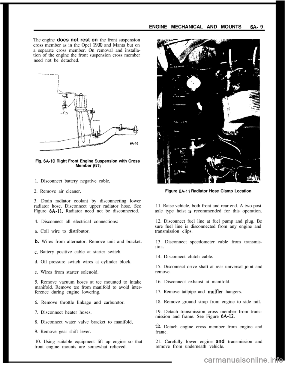
The engine does not rest on the front suspension
cross member as in the Opel 1900 and Manta but on
a separate cross member. On removal and installa-
tion of the engine the front suspension cross member
need not be detached.
Fig. 6A-10 Right Front Engine Suspension with Cross
Member
(GT)1. Disconnect battery negative cable,
2. Remove air cleaner.
3. Drain radiator coolant by disconnecting lower
radiator hose. Disconnect upper radiator hose. See
Figure 6A-11. Radiator need not be disconnected.
4. Disconnect all electrical connections:
a. Coil wire to distributor.
b. Wires from alternator. Remove unit and bracket.
c. Battery positive cable at starter switch.
d. Oil pressure switch wires at cylinder block.
e. Wires from starter solenoid.
5. Remove vacuum hoses at tee mounted to intake
manifold. Remove tee from manifold to avoid inter-
ference during engine lowering.
6. Remove throttle linkage and carburetor.
7. Disconnect heater hoses.
8. Disconnect water valve bracket to manifold,
9. Remove gear shift lever.
10. Using suitable equipment lift up engine so that
front engine mounts are somewhat relieved.Figure 6A.1
1 Radiator Hose Clamp Location
11. Raise vehicle, both front and rear end. A two post
axle type hoist
IS recommended for this operation.
12. Disconnect fuel line at fuel pump and plug. Be
sure fuel line is disconnected from any engine and
transmission clips.
13. Disconnect speedometer cable from transmis-
sion.14. Disconnect clutch cable.
15. Disconnect drive shaft at rear universal joint and
remove.
16. Disconnect exhaust at manifold.
17. Remove tailpipe and mufIler hangers.
18. Remove ground strap from engine to side rail.
19. Detach transmission cross member from trans-
mission and frame. See Figure 6A-12.
20. Detach engine cross member from engine and
frame.21. Carefully lower engine and transmission and
remove from underneath vehicle.
Page 303 of 625
6A- 121973 OPEL SERVICE MANUALINTAKE AND EXHAUST MANIFOLD REMOVAL
AND
INSTALLATION
Removal1. Disconnect battery.
2. Remove air cleaner.
3. Disconnect throttle linkage at carburetor.
4. Disconnect vacuum advance line at carburetor.
5. Remove fuel line at carburetor inlet.
6. Remove positive crankcase ventilation hose at
rocker arm cover.
7. Disconnect E.G.R. lines from carburetor and in-
take manifold.
8. Disconnect exhaust pipe.
9. Remove six bolts attaching manifold assembly to
cylinder head and remove manifold and carburetor
as an assembly. Discard manifold gasket.
To separate intake and exhaust, manifold, remove
carburetor and four bolts using Tool J-23016, attach-
ing intake manifold to exhaust manifold. Always in-
stall a new manifold intermediate gasket when the
manifolds are separated.
Installation1. Install new manifold gasket and place manifold in
position.
2. Install manifold bolts. New manifold to cylinder
head gasket must be installed whenever a manifold
is removed.
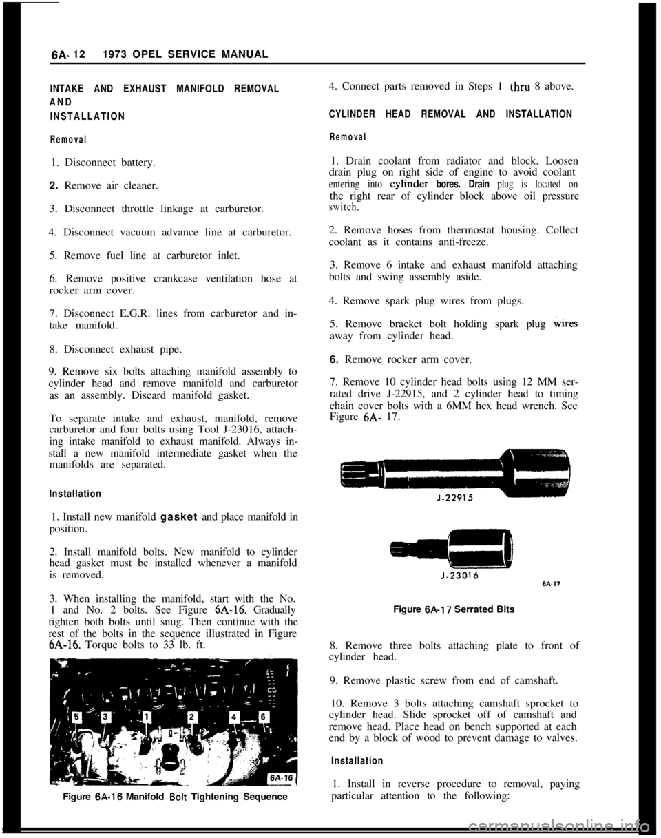
3. When installing the manifold, start with the No.
1 and No. 2 bolts. See Figure 6A-16. Gradually
tighten both bolts until snug. Then continue with the
rest of the bolts in the sequence illustrated in Figure6A-16. Torque bolts to 33 lb. ft.
Figure 6A-16 Manifold
Bolt Tightening Sequence4. Connect parts removed in Steps 1 thru 8 above.
CYLINDER HEAD REMOVAL AND INSTALLATION
Removal1. Drain coolant from radiator and block. Loosen
drain plug on right side of engine to avoid coolant
entering into cylmder bores. Drain plug is located onthe right rear of cylinder block above oil pressure
switch.2. Remove hoses from thermostat housing. Collect
coolant as it contains anti-freeze.
3. Remove 6 intake and exhaust manifold attaching
bolts and swing assembly aside.
4. Remove spark plug wires from plugs.
5. Remove bracket bolt holding spark plug wires
away from cylinder head.
6. Remove rocker arm cover.
7. Remove 10 cylinder head bolts using 12 MM ser-
rated drive J-22915, and 2 cylinder head to timing
chain cover bolts with a 6MM hex head wrench. See
Figure 6A- 17.
Figure 6A-17 Serrated Bits
8. Remove three bolts attaching plate to front of
cylinder head.
9. Remove plastic screw from end of camshaft.
10. Remove 3 bolts attaching camshaft sprocket to
cylinder head. Slide sprocket off of camshaft and
remove head. Place head on bench supported at each
end by a block of wood to prevent damage to valves.
Installation1. Install in reverse procedure to removal, paying
particular attention to the following:
Page 327 of 625
6C- 361973 OPEL SERVICE MANUAL
FUEL SYSTEM
ALL MODELS
CONTENTS
Subject
DESCRIPTION AND OPERATION:
Fuel Pump. . . . . . . . . . . . . . . . . . . . . . . . . . . . . . . . . . . . . . . . . . . . . . . . . . . . . . . . . . . . . . . . .. . . . . . . . . . .Evaporation Control System
. . . . . . . . . . . . . . . . . . . . . . . . . . . . . . . . . . . . . . . . . .DIAGNOSIS:
(Not Applicable)
MAINTENANCE AND ADJUSTMENTS:
Cleaning Fuel Pump Strainer.,....................................
*.Evaporation Control System
. . . . . . . . . . . , . . . . . . . . . . . . . . . . . . . . . . . . . . . . . .MAJOR REPAIR:
Fuel Tank
. . . . . . . . . . . . . . . . . . . . . . . . . . . . . . . . . . . . . . . . . . . . . . . . . . . . . . . . . . . . . . . . . . . . . . . . . . . . . .Fuel Lines and Fuel Tank Gauge Units
. . . . . . . . . . . . . . . . . . . . . .SPECIFICATIONS:
Fuel System Specifications
. . . . . . . . . . . . . . . . . . . . . . . . . . . . . . . . . . . . . . . . . . .Page No.6C-366C-376C-376C-386C-396C-416C-41
DESCRIPTION AND OPERATION
FUEL PUMPThe 1.9 liter engine uses a push rod type fuel pump.
The push rod is actuated by an eccentric on the
distributor shaft. The push rod is held in contact
with the eccentric at all times by a push rod spring.
Each time the push rod is on the high part of the
eccentric, the lighter diaphragm spring will push the
diaphragm to replace any fuel used in the carburetor.
The diaphragm seldom operates through a full
stroke; under normal driving conditions, the dia-
phragm moves only a few tenths of an inch.
Fuel pump pressure is determined by the compres-
sion of the diaphragm spring. Low pressure or pres-
sure leak- down generally indicates a leaky
diaphragm or check valves.
Two holes in the lower part of the fuel pump serve
to ventilate the space below the diaphragm and to
drain any fuel which may have entered. If any fuel
comes from these holes, this indicates a defective
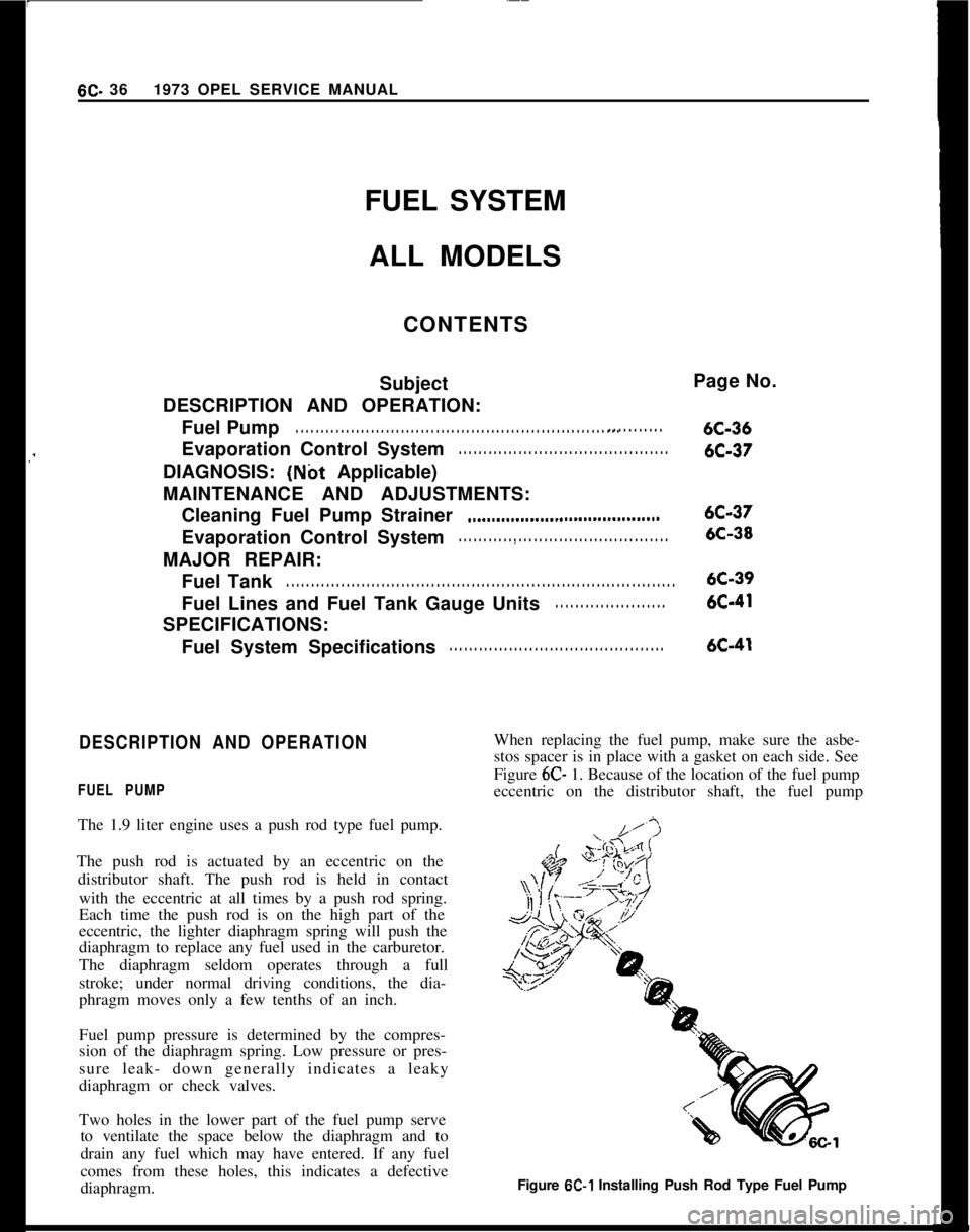
diaphragm.When replacing the fuel pump, make sure the asbe-
stos spacer is in place with a gasket on each side. See
Figure 6C- 1. Because of the location of the fuel pump
eccentric on the distributor shaft, the fuel pump
Figure
6C-1 Installing Push Rod Type Fuel Pump