oil dipstick OPEL MANTA 1973 Service Manual
[x] Cancel search | Manufacturer: OPEL, Model Year: 1973, Model line: MANTA, Model: OPEL MANTA 1973Pages: 625, PDF Size: 17.22 MB
Page 16 of 625
LUBRICATION AND MAINTENANCE OC-7SERVICESLUBE AND GENERAL MAINTENANCE
Vehicle operation under conditions such as heavy
dust, continuous short trips, use of other than un-
leaded or low lead fuels or pulling trailers, is not
considered normal use and therefore more frequent
maintenance will be required. Such additional
maintenance requirements are included where appli-
cable.
Engine OilChange each 4 months or
3,COO miles, whichever
occurs first, or each 2 months or
3,ooO miles when
the vehicle is operated under the following condi-
tions: (a) driving in dusty conditions, (b) trailer pull-
ing, (c) extensive idling or (d) short-trip operation at
freezing temperatures (with engine not thoroughly
warmed-up).Engine oils have a definite effect on ease of starting,
oil economy, combustion chamber deposits and en-
gine wear. It is recommended that a” oil which,
according to the label on the can is; (1) intended for
service SE and (2) passes car makers’ tests be used.
Oils confotming to these types contain detergent ad-
ditives. -
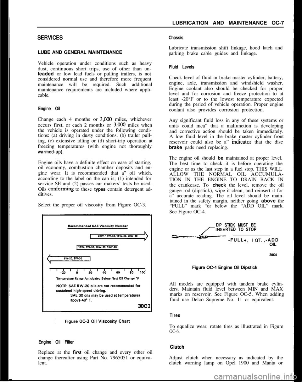
Select the proper oil viscosity from Figure OC-3.
Engine Oil FilterReplace at the first oil change and every other oil
change thereafter using Part No. 7965051 or equiva-
lent.
ChassisLubricate transmission shift linkage, hood latch and
parking brake cable guides and linkage.
Fluid LevelsCheck level of fluid in brake master cylinder, battery,
engine, axle, transmission and windshield washer.
Engine coolant also should be checked for proper
level and for corrosion and freeze protection to at
least -20°F or to the lowest temperature expected
during the period of vehicle operation. Proper engine
coolant also provides corrosion protection.
Any significant fluid loss in any of these systems or
units could mea” that a malfunction is developing
and corrective action should be taken immediately.
A low fluid level in the brake master cylinder front
reservoir could also be a” indtcator that the disc
brake pads need replacing.
The engine oil should be maintained at proper level.
The best time to check it is before operating the
engine or as the last step in a fuel stop. THIS WILL
ALLOW THE NORMAL OIL ACCUMULA-
TION IN THE ENGINE TO DRAIN BACK IN
the crankcase. To check the level, remove the oil
gauge rod (dipstick), wipe it clean, and reinsert it for
a” accurate reading. The oil level should be main-
tained in the safety margin, neither going above the
“FULL” mark “or below the “ADD OIL” mark.
See Figure OC-4.
DIP STICK MUST BE
INSERTED TO STOP
---L- -FULL+, 1 OT. ,-ADD
OIL
Figure OC-4 Engine Oil Dipstick
All models are equipped with tandem brake cylin-
ders. Maintain fluid level between MIN and MAX
marks on reservoir. See Figure OC-5. When adding
fluid use Delco Supreme No. 11 or equivalent.
TiresTo equalize wear, rotate tires as illustrated in Figure
OC-6.Adjust clutch when necessary as indicated by the
clutch warning lamp on Opel 1900 and Manta or
Page 297 of 625
6A. 61973 OPEL SERVICE MANUALDIAGNOSIS
EXCESSIVE OIL CONSUMPTION
ConditionCorrectionExternal Oil Leaks at:Tighten attaching bolts. If leaks
Rocker Arm Coverspersist, remove cover (or pan),
Crankcase Front Covercheck sealing surfaces for burrs
Oil Pan and Gasketor scoring, replace gasket, and
seal bolts with silastic sealer or
equivalent. Make sure oil level
,is not overfull.
Improper Reading of Dip-Car may not be level when taking r
StickInsuffIcient oil “drain-back” time
after stopping engine (three
minutes must be allowed). Dip-
stick may not be completely pushed
down against stop. Dipstick may
be bent.
Oil Viscosity Too LightUse recommended SAE viscosity for
prevailing temperatures.
Continuous High-SpeedAt speeds above 60 mph, increased
Drivingsumption can be expected with any
Inform customer of this fact.
High-Speed DrivingWhen principal use of automobile i
Following Normal Slowcity driving, crankcase dilution f
Speed City Drivingcondensation occurs. High speed a
temperatures will remove water,
resulting in what appears to be
rapid lowering of oil level.
Inform customer of this fact.
Piston Rings NotAllow engine to accumulate at leas
“Broken In”
4,OCO miles before attempting any
engine disassembly to correct for
oil consumption.
NOISY VALVES AND LIFTERSIf the preceding check indicates valve mechanism is
abnormally noisy, remove the rocker arm cover so
that the various conditions that cause noise may be
The noise level of the valve mechanism cannot bechecked. A piece of heater hose of convenient length
properly judged where the engine is below operatingmay be used to pick out the particular valves or valve
temperature when the hood is raised, or when thelinkages
thit are causing abnormal noise. With the
valve rocker arm covers are removed.engine running at a speed where the noise is pro-
nounced; hold the end of hose to an ear and hold
Before attempting to judge valve noise level, the en-other end about
l/2 inch from point of contact be-
gine must be thoroughly warmed up (at least 20tween rocker arm and valve stem. Mark or record the
minutes of operation at
1200 to 1500 RPM) to stabil-noisy valves for investigation of following causes:ize oil and coolant temperatures and bring all engine
parts to a normal state of expansion. When the
en-1. Sticking, Warped, or Eccentric Valves, Worngine is warmed up, listen for engine noise while
sit-Guides Sticking valves will cause irregular engine
ting in the driver’s seat with the hood closed. Run theoperation or missing on a low speed pull and will
engine at idle and at various higher speeds.usually cause intermittent noise.
Page 442 of 625
DIAGNOSIS
SEQUENCE
1. Check and correct oil level. Refer to Specifications
for checking and refill procedures.
2. Check and correct vacuum line and fittings.
3. Check and correct manual linkage.
4. Road test car using all selective ranges, noting
when discrepancies in operation occur.
5. If engine performances indicates an engine tuneup
is required, this should be performed before road
testing is completed or transmission correction at-
tempted. Poor engine performance can result in
rough shifting or other malfunctions.
CHECKING PROCEDURESBefore diagnosis of any transmission complaint is
attempted, there must be an understanding of oil
checking procedure and what appearance the oil
should have. Many times a transmission malfunction
can be traced to low oil level, improper reading of
dipstick, or oil appearances; therefore, a careful anal-
ysis of the condition of oil and the level may elimi-
nate needless repairs.
When checking oil level in the Opel Three Speed
Automatic Transmission, the procedure outlined in
Specifications should be followed to obtain the most
accurate reading.
Also when the dipstick is removed, it should be noted
whether the oil is devoid of air bubbles or not. Oil
with air bubbles gives an indication of an air leak in
the suction lines, which can cause erractic operation
and slippage. Water in the oil imparts a milky, pink
cast to the oil and can cause spewing.
EXTERNAL OIL LEAKS
Determining source of oil leakBefore attempting to correct an oil leak, the actual
source of the leak must be determined. In many
cases, the source of the leak can be deceiving due to
“wind flow” around the engine and transmission.
The suspected area should be wiped clear of all oil
before inspecting for the source of the leak. Red dyeAUTOMATIC TRANSMISSION 7C- 81
is used in the transmission oil at the assembly plant
and will indicate if the oil leak is from the transmis-
sion.The use of a “Black Light” to locate the point at
which the oil is leaking is helpful. Comparing the oil
from the leak to that on the engine or transmission
dipstick, when viewed by Black Light, will determine
the source of the leak-engine or transmission.
Oil leaks around the engine and transmission are
generally carried toward the rear of the car by air
stream. For example, a transmission oil filler tube to
case leak will sometimes appear as a leak at the rear
of the transmission. In determining the source of a
leak, proceed as follows:
1. Degrease underside of transmission.
2. Road test to get unit at operating temperature.
3. Inspect for leak with engine running.
4. With engine off, check for oil leaks due to the
raised oil level caused by drain back.
Case Porosity RepairOpel Three-Speed Automatic Transmission external
oil leaks caused by case porosity can be successfully
repaired with the transmission in the car by using the
following recommended procedures:
1. Road test and bring the transmission to operating
temperature, approximately 180 degrees F.
2. Raise car on a hoist or jack stand, engine running,
and locate source of oil leak. Check for oil leaks in
low, drive, and reverse.
3. Shut engine off and thoroughly clean area to be
repaired with a suitable cleaning solvent and a
brush- air dry. A clean, dry soldering acid brush can
be used to clean the area and also to apply the epoxy
cement.
4. Using instructions of the manufacturer, mix a suf-
ficient amount of epoxy, BUICK Group 0.423, Part
No. 1360016, or equivalent, to make the repair. Ob-
serve cautions of manufacturer in handling.
5. While the transmission case is still HOT, apply the
epoxy to the area to be repaired. Make certain the
area to be repaired is fully covered.
6. Allow cement to cure for 3 hours before starting
engine.
7. Road test and check for leaks.
Page 455 of 625
7C. 941973 OPEL SERVICE MANUAL
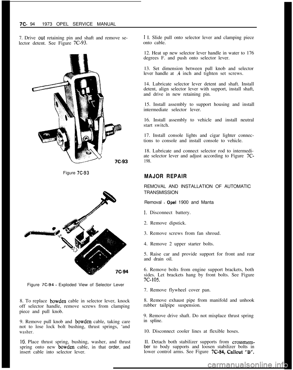
7. Drive out retaining pin and shaft and remove se-
lector detent. See Figure 7C-93.Figure
7C-93Figure
7C-94 - Exploded View of Selector Lever
8. To replace bowden cable in selector lever, knock
off selector handle, remove screws from clamping
piece and pull knob.
9. Remove pull knob and bowden cable, taking care
not to lose lock bolt bushing, thrust springs, ‘and
washer.
10. Place thrust spring, bushing, washer, and thrust
spring onto new bowden cable, in that order, and
insert cable into selector lever.
1 I. Slide pull onto selector lever and clamping piece
onto cable.
12. Heat up new selector lever handle in water to 176
degrees F. and push onto selector lever.
13. Set dimension between pull knob and selector
lever handle at
.4 inch and tighten set screws.
14. Lubricate selector lever detent and shaft. Install
detent, align selector lever with support, install shaft,
and drive in new retaining pin.
15. Install assembly to support housing and install
intermediate selector lever.
16. Install assembly to vehicle and install neutral
start switch.
17. Install console lights and cigar lighter connec-
tions to console and install console to vehicle.
18. Lubricate and connect selector rod to intermedi-
ate selector lever and adjust according to Figure 7C-
198.
MAJOR REPAIRREMOVAL AND INSTALLATION OF AUTOMATIC
TRANSMISSION
Removal
- Opel 1900 and Manta
I. Disconnect battery.
2. Remove dipstick.
3. Remove screws from fan shroud.
4. Remove 2 upper starter bolts.
5. Raise car and provide support for front and rear
and drain oil.
6. Remove bolts from engine support brackets, both
sides. Let brackets hang by front bolts. See Figure7c-105.
7. Remove flywheel cover pan.
8. Remove exhaust pipe from manifold and unhook
rubber tailpipe suspension.
9. Remove drive shaft. Do not misplace thrust spring
in spline.
10. Disconnect cooler lines at flexible hoses.
II. Detach both stabilizer supports from
crossmem-ber to body supports and loosen stabilizer bolts in
lower control arms. See Figure X-84, Callout “B”,
Page 456 of 625
AUTOMATIC TRANSMISSION 7C- 95
12. Place suitable jack under transmission and
remove transmission support bolts.
13. Lower transmission enough to remove detent
cable and modulator vacuum line.
14. Remove speedometer cable.
15. Remove selector lever.
16. Mark flywheel and converter for reassembly in
same position, and remove converter to flywheel
bolts. See Figure 7C-106.17. Remove converter housing to engine bolts and
tiller tube.
18. Pry transmission loose from engine.
19. Keep rear of transmission lower than front to
prevent converter from falling and install converter
holding fixture J-21366. Lower transmission and
move to bench.
Installation. Opel 1900 and Manta1. Assemble transmission to suitable jack and raise
transmission into position. Rotate converter to per-
mit coupling of fly wheel and converter with original
relationship. Remove J-21366.
2. Install tiller tube and converter housing to engine
block bolts. Torque to 35 lb. ft. DO NOT over
torque.
3. Install flywheel to converter bolts. Torque to 30 lb.
ft.4. Install detent cable to transmission.
5. Connect oil cooler lines.
6. Install lower bolt on starter. Torque to 40 lb. ft.
7. Connect shift linkage to transmission.
8. Connect modulator line.
9. Connect speedometer cable.
10. Install transmission support.
11. Install drive shaft. Torque U-Bolts to 18 lb. ft.
12. Install flywheel cover pan. Torque to 15 lb. ft.
13. Install engine support brackets.
14. Reconnect exhaust system.15. Attach stabilizer supports and tighten stabilizer
bolts in lower control arms.
16. Lower car.
17. Install starter bolts. Torque to 40 lb. ft.
18. Reconnect battery.
19. Fill transmission with fluid as described in
Specifications. Check selector lever and detent cable
adjustment.
Removal GT1. Disconnect battery.
2. Remove dipstick.
3. Pull throttle control rod off ball pin.
4. Remove screws from fan shroud.
5. Raise car and provide support for front and rear.
6. Remove heat protection shield from right side to
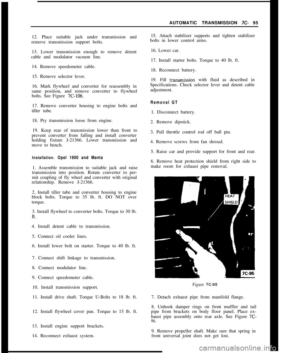
make room for exhaust pipe removal.
Figure 7C-957. Detach exhaust pipe from manifold flange.
8. Unhook damper rings on front muffler and tail
pipe from brackets on body floor panel. Place ex-
haust pipe assembly onto rear axle. See Figure 7C-
96.9. Remove propeller shaft. Make sure that spring in
front universal joint does not get lost.
Page 495 of 625
7C-1341973 OPEL SERVICE MANUAL
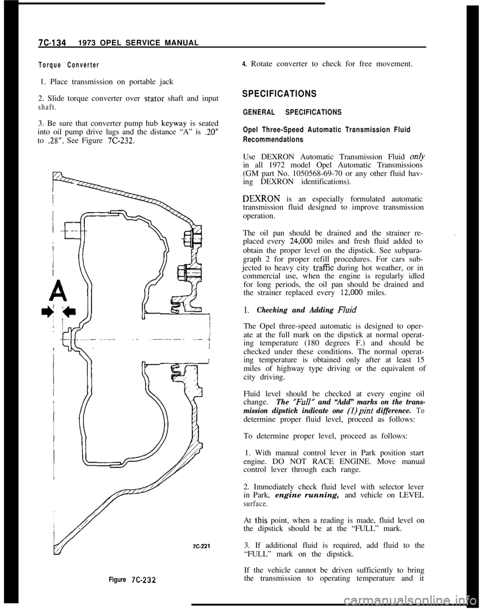
Figure 7C-232
Torque Converter4. Rotate converter to check for free movement.
1. Place transmission on portable jack
2. Slide torque converter over stator shaft and input
shaft.3. Be sure that converter pump hub keyway is seated
into oil pump drive lugs and the distance “A” is
.20”to
.28”. See Figure 7C-232.
SPECIFICATIONS
GENERAL SPECIFICATIONS
Opel Three-Speed Automatic Transmission Fluid
RecommendationsUse DEXRON Automatic Transmission Fluid on/y
in all 1972 model Opel Automatic Transmissions
(GM part No. 1050568-69-70 or any other fluid hav-
ing DEXRON identifications).DEXIRON is an especially formulated automatic
transmission fluid designed to improve transmission
operation.
The oil pan should be drained and the strainer re-
placed every
24,ooO miles and fresh fluid added to
obtain the proper level on the dipstick. See subpara-
graph 2 for proper refill procedures. For cars sub-
jected to heavy city
traff%z during hot weather, or in
commercial use, when the engine is regularly idled
for long periods, the oil pan should be drained and
the strainer replaced every
12,ooO miles.
.
1.Checking and Adding FluidThe Opel three-speed automatic is designed to oper-
ate at the full mark on the dipstick at normal operat-
ing temperature (180 degrees F.) and should be
checked under these conditions. The normal operat-
ing temperature is obtained only after at least 15
miles of highway type driving or the equivalent of
city driving.
Fluid level should be checked at every engine oil
change.
The “FuIl” and “Add” marks on the trans-
mission dipstick indicate one (1)pint
difference. Todetermine proper fluid level, proceed as follows:
To determine proper level, proceed as follows:
1. With manual control lever in Park position start
engine. DO NOT RACE ENGINE. Move manual
control lever through each range.
2. Immediately check fluid level with selector lever
in Park, engine running, and vehicle on LEVEL
surface.At
t,his point, when a reading is made, fluid level on
the dipstick should be at the “FULL” mark.
3. If additional fluid is required, add fluid to the
“FULL” mark on the dipstick.
If the vehicle cannot be driven sufficiently to bring
the transmission to operating temperature and it
Page 496 of 625
AUTOMATIC TRANSMISSION 7C-135
becomes necessary to check the fluid level, the trans-
mission may be checked at room temperature (70
degrees F.) as follows:
1. With manual control lever in Park position start
engine. DO NOT RACE ENGINE. Move manual
control lever through each range.
2. lmmediately check fluid level with selector lever
in Park, engine running, and vehicle on LEVEL sur-
face.At this point, when a reading is made, fluid level on
the dipstick should be I/4” below the “ADD” mark.
3. If additional fluid is required add fluid to bring
level to
l/4” below the “ADD” mark on the dip-
stick.If transmission fluid level is correctly established at
70 degrees F. it will appear at the “FULL” mark on
the dipstick when the transmission reaches normal
operating temperature (180 degrees F.) The fluid
level is set
l/4” below the “ADD” mark on the
dipstick to allow for expansion of the fluid which
occurs as transmission temperatures rise to normal
operating temperature of 180 degrees F.
Do not overfill, as foaming and loss of fluid through
the vent pipe might occur as fluid heats up. If fluid
is too low especially when cold, complete loss
of’drive may result which can cause transmission fail-
ure.
2.Draining oilpan and rep/a&g strainer assembly.
(a) Raise car on hoist or p/ace OnJxk stands, and
provide container to collect draining fluid.
(b) Remove oil pan and gasket. Discard gasket.
(c) Drain fluid from oil pan. Clean pan with solvent
and dry thoroughly with clean compressed air.
(d) Remove strainer assembly, strainer gasket and
discard.
(e) Install new oil strainer gasket. Install new strainer
assembly.
(f) Install new gasket on oil pan and install pan.
Tighten attaching bolts to 7-10 lb. ft.
(g) Lower car and add approximately three (3) pints
of transmission fluid through filler tube.
(h) With manual control lever in Park position, start
engine. DO NOT RACE ENGINE. Move manual
control lever through each range.
(i) Immediately check fluid level with selector leverin Park, engine running, and vehicle on LEVEL
sur-
face.(i) Add additional fluid to bring level to
l/4” below
the “ADD” mark on the dipstick. Do not overfill.
3.Adding Fluid to Fill Dry Transmission and Con-
verter Assembly
The fluid capacity of the Opel Three Speed Auto-
matic transmission and converter assembly is ap-
proximately IO-l/2 pints, but correct level is
determined by the mark on the dipstick rather than
by amount added. In cases of transmission overhaul,
when a complete fill is required, including a new
converter proceed as follows:
(a) Add approximately 10-l/2 pints of transmission
fluid through tiller tube.
The converter should be replaced on any major fail-
ure, such as a clutch or gearset, and an excessive
amount of foreign material is indicated in the pan. If
installation of a new converter is not required add
approximately five (5) pints of transmission fluid.
(b) With manual control lever in Park position start
engine and run at 1000 RPM. DO NOT RACE EN-
GINE. Move manual control lever through each
range.
(c) Immediately check fluid level with selector lever
in Park, engine running, and vehicle on LEVEL
sur-
face.(d) Add additional fluid to bring level to
l/4” below
the “ADD” mark on the dipstick. Do not overfill.
Opel Three Speed Automatic Transmission Towing
Instructions
If an Opel equipped with an automatic transmission
must be towed, the following precautions must be
observed:
The car may be towed safely on its rear wheels with
the shift lever in neutral position at speeds of 35 miles
per hour or less under most conditions.
However, the drive shaft must be disconnected or the
car towed on its front wheels if:
a. Tow speeds in excess of 35 mph are necessary.
b. Car must be towed for extended distances (over 50
miles).
c. Transmission is not operating properly.
If car is towed on its front wheels, the steering wheel