Bulb OPEL MERIVA 2009 Owners Manual
[x] Cancel search | Manufacturer: OPEL, Model Year: 2009, Model line: MERIVA, Model: OPEL MERIVA 2009Pages: 248, PDF Size: 4.46 MB
Page 90 of 248
84 Instruments, Controls
Picture no: 17876s.tif
I
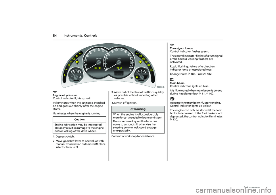
Engine oil pressure
Control indicator lights up red
It illuminates when the ignition is switched
on and goes out shortly after the engine
starts.
Illuminates when the engine is running
1. Depress clutch.
2. Move gearshift lever to neutral, or with
manual transmissi on automated 3 place
selector lever in N.
Picture no:
3. Move out of the flow of traffic as quickly
as possible without impeding other
vehicles.
4. Switch off ignition.
Contact a workshop for assistance.
Caution
Engine lubrication may be interrupted.
This may result in damage to the engine
and/or locking of the drive wheels.
9 Warning
When the engine is off, considerably
more force is needed to brake and steer.
Do not remove key until vehicle has
come to a standstill, otherwise the
steering column lock could engage
unexpectedly.
O
Turn signal lamps
Control indicator flashes green.
The control indicator flashes if a turn signal
or the hazard warning flashers are
activated.
Rapid flashing: failure of a direction
indicator lamp or associated fuse.
Change bulbs 3 185. Fuses 3182.
C
Main beam
Control indicator lights up blue.
It is illuminated when main beam is on and
during headlamp flash 311, 3102.
j
Automatic transmission 3, start engine.
Control indicator lights up yellow.
The engine can only be started if the foot
brake is depressed. If the foot brake is not
depressed, the control indicator illuminates
3 130.
Page 169 of 248
163
Driving and operation
Coupling socket load
The coupling socket load is the load
exerted by the trailer/caravan on the
coupling ball. It can be varied by changing
the weight distribution when loading the
trailer/caravan.
The maximum permissible coupling socket
load (55 kg) of the towing vehicle is
specified on the towing equipment
identification plate and in the vehicle
documents. This must always be complied
with, particularly in the case of heavy
caravans/trailers. The coupling socket load
should be no less than 25 kg.
When measuring the coupling socket load,
make sure that the drawbar of the loaded
trailer/caravan is at the same height as it
will be when the trailer/caravan is coupled
with the towing vehicle loaded. Particularly
important for trailers/caravans with
tandem axle. Rear axle load during towing
With the trailer connected and the towing
vehicle fully loaded including all
occupants, the permitted rear axle load
(specified on the identification plate and
vehicle documents) must be exceeded by
no more than 25 kg and the maximum
permitted gross vehicle weight by no more
than 30 kg. If the maximum permitted rear
axle load is exceeded, a maximum speed
of 100 km/h applies, and 80 km/h for
commercial vehicles.
Driving characteristics, towing tips
Before attaching th
e trailer/caravan,
lubricate the ball of the trailer/caravan
towing device. However, do not lubricate
the ball if a stabiliser, which acts on the
coupling ball, is being used to damp
hunting.
Check caravan/traile r lighting before
starting to drive. The fog tail lamps on the
vehicle are deactivated when towing a
caravan or trailer.
Trailers with LED turn signals must have a
provision enables lamp monitoring for
commercial bulbs.
Handling is greatly influenced by the
loading of the trailer/caravan. Loads
should therefore be secured so that they
cannot slip and be placed in the centre of
the trailer/caravan if possible, i.e. above
the axle.
In the case of trailers with low driving
stability, do not exceed a speed of 80 km/h;
the use of a friction-type stabiliser is
strongly recommended.
Page 171 of 248
165
Self-help, vehicle care
Self-help, vehicle care
Diesel fuel system, bleeding If the tank is allowed to run dry, the diesel
fuel system must be bled. Turn over the
ignition three times for 15 seconds at a
time. Then start the engine for a maximum
of 40 seconds
1). Repeat this process after
no less than 5 seconds. If the engine fails to
start, seek the assistance of a workshop.
Picture no: 16109s.tif
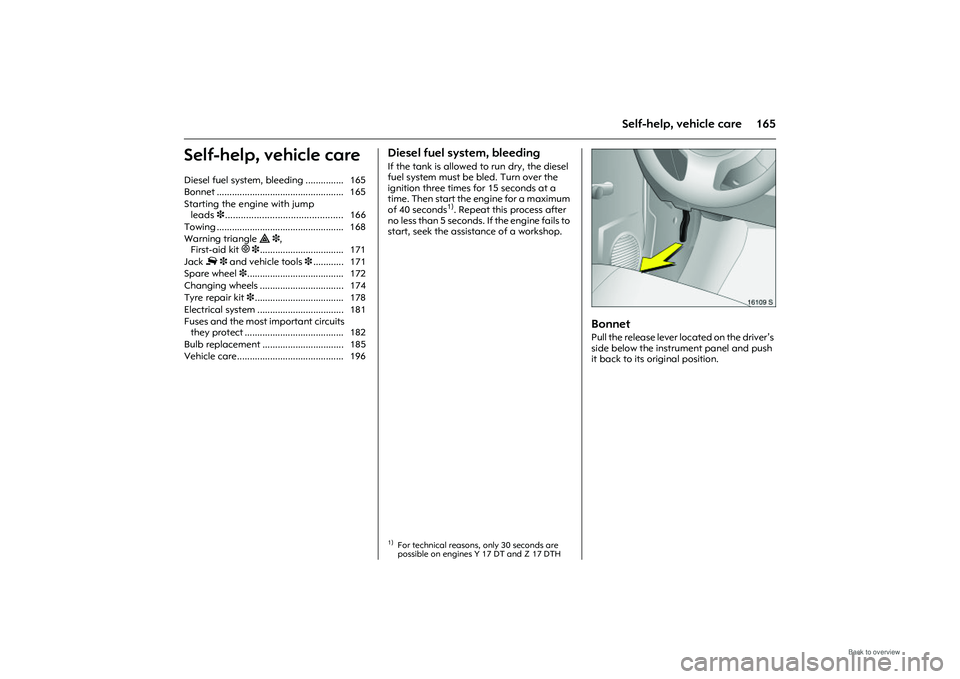
Bonnet Pull the release lever lo cated on the driver’s
side below the instru ment panel and push
it back to its original position.
Diesel fuel system, bleeding ............... 165
Bonnet .................................................. 165
Starting the engine with jump
leads 3............................................. 166
Towing .................................................. 168
Warning triangle ¨ 3,
First-aid kit +3................................. 171
Jack £ 3 and vehicle tools 3............ 171
Spare wheel 3...................................... 172
Changing wheels ................................. 174
Tyre repair kit 3................................... 178
Electrical system .................................. 181
Fuses and the most important circuits they protect ....................................... 182
Bulb replacement ................................ 185
Vehicle care.......................................... 196
1)For technical reasons, only 30 seconds are
possible on engines Y 17 DT and Z 17 DTH
Page 191 of 248
185
Self-help, vehicle care
Picture no: 14214s.tif
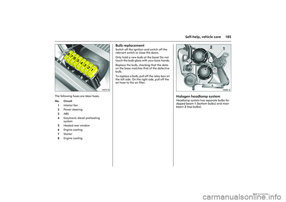
The following fuses are Maxi fuses.
Bulb replacement Switch off the ignition and switch off the
relevant switch or close the doors.
Only hold a new bulb at the base! Do not
touch the bulb glass with your bare hands.
Replace the bulb, checking that the data
on the base matches that of the defective
bulb.
To replace a bulb, pull off the relay box on
the left side. On the right side, pull off the
air hose to the air filter.
Picture no: 16085s.tif
Halogen headlamp systemHeadlamp system has separate bulbs for
dipped beam 1 (bottom bulbs) and main
beam 2 (top bulbs).
No. Circuit
1 Interior fan
2 Power steering
3 ABS
4 Easytronic diesel preheating
system
5 Heated rear window
6 Engine cooling
7 Starter
8 Engine cooling
Page 192 of 248
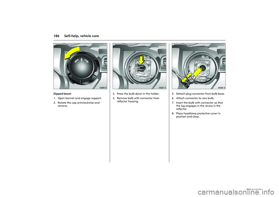
186 Self-help, vehicle care
Picture no: 16086s.tif
Dipped beam
1. Open bonnet and engage support.
2. Rotate the cap anticlockwise and remove.
Picture no: 16087s.tif
3. Press the bulb do wn in the holder.
4. Remove bulb with connector from reflector housing.
Picture no: 16088s.tif
5. Detach plug connector from bulb base.
6. Attach connector to new bulb.
7. Insert the bulb with connector so that the lug engages in the recess in the
reflector.
8. Place headlamp protective cover in position and close.
Page 193 of 248
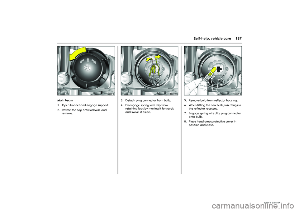
187
Self-help, vehicle care
Picture no: 16089s.tif
Main beam
1. Open bonnet and engage support.
2. Rotate the cap anticlockwise and remove.
Picture no: 16090s.tif
3. Detach plug connector from bulb.
4. Disengage spring wire clip from
retaining lugs by moving it forwards
and swivel it aside.
Picture no: 16091s.tif
5. Remove bulb from reflector housing.
6. When fitting the new bulb, insert lugs in the reflector recesses.
7. Engage spring wire clip, plug connector
onto bulb.
8. Place headlamp protective cover in position and close.
Page 194 of 248
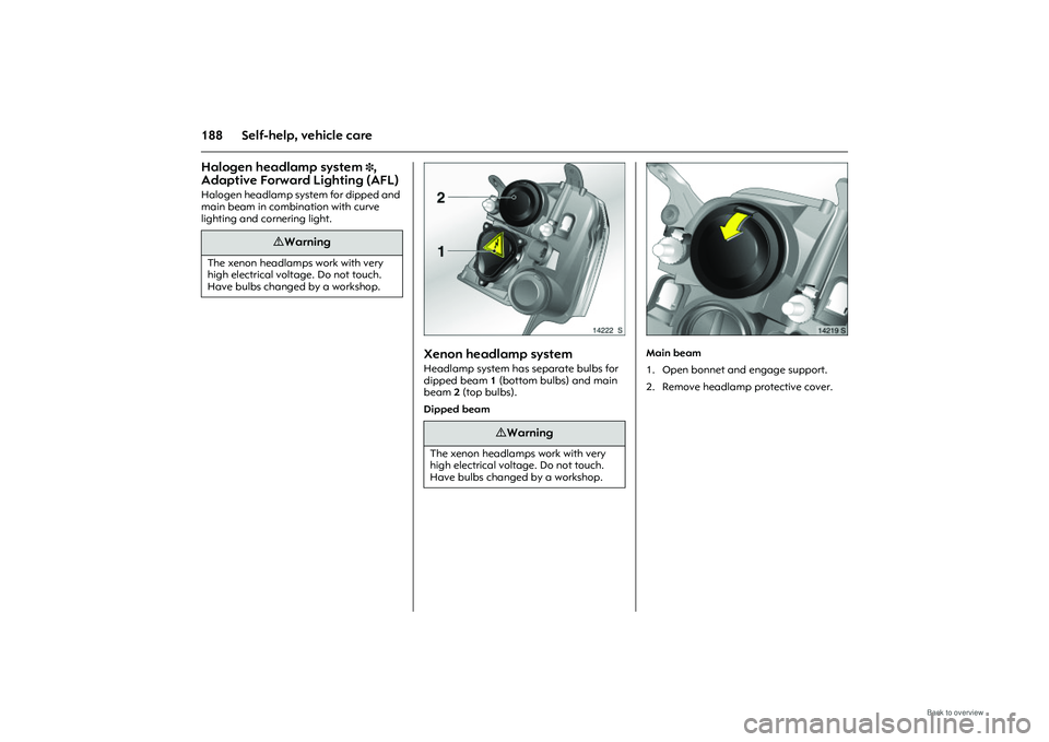
188 Self-help, vehicle careHalogen headlamp system
3,
Adaptive Forward Lighting (AFL)
Halogen headlamp system for dipped and
main beam in comb ination with curve
lighting and cornering light.
Picture no: 14222s.tif
Xenon headlamp systemHeadlamp system has separate bulbs for
dipped beam 1 (bottom bulbs) and main
beam 2 (top bulbs).
Dipped beam
Picture no: 14219s.tif
Main beam
1. Open bonnet and engage support.
2. Remove headlamp protective cover.
9 Warning
The xenon headlamps work with very
high electrical voltage. Do not touch.
Have bulbs changed by a workshop.
9 Warning
The xenon headlamps work with very
high electrical volt age. Do not touch.
Have bulbs changed by a workshop.
Page 195 of 248
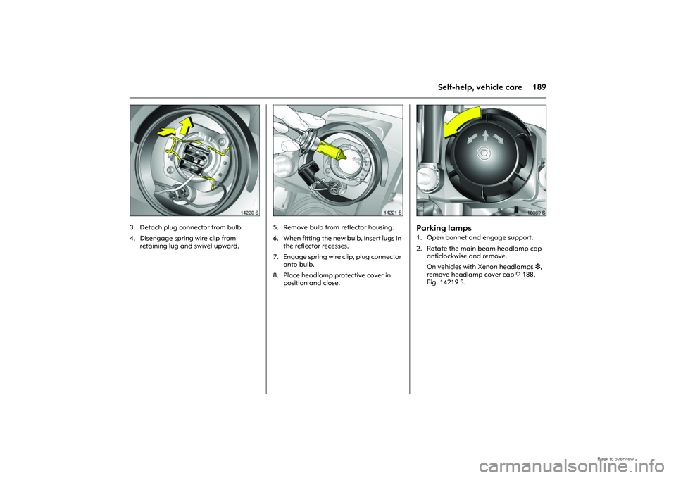
189
Self-help, vehicle care
Picture no: 14220s.tif
3. Detach plug connector from bulb.
4. Disengage spring wire clip from retaining lug and swivel upward.
Picture no: 14221s.tif
5. Remove bulb from reflector housing.
6. When fitting the new bulb, insert lugs in
the reflector recesses.
7. Engage spring wire clip, plug connector onto bulb.
8. Place headlamp protective cover in position and close.
Picture no: 16089s.tif
Parking lamps 1. Open bonnet and engage support.
2. Rotate the main beam headlamp cap anticlockwise and remove.
On vehicles with Xenon headlamps 3 ,
remove headlamp cover cap 3188,
Fig. 14219 S.
Page 196 of 248
190 Self-help, vehicle care
Picture no: 16092s.tif
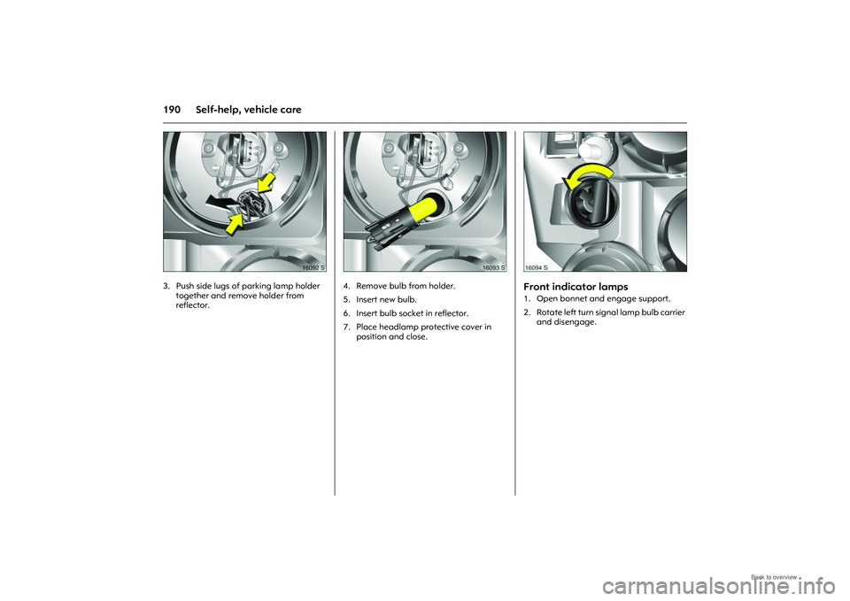
3. Push side lugs of parking lamp holder together and remove holder from
reflector.
Picture no: 16093s.tif
4. Remove bulb from holder.
5. Insert new bulb.
6. Insert bulb socket in reflector.
7. Place headlamp protective cover in position and close.
Picture no: 16094s.tif
Front indicator lamps 1. Open bonnet and engage support.
2 . R o ta te l ef t t u r n s i g n a l l a m p bu l b c a r r i e r and disengage.
Page 197 of 248
191
Self-help, vehicle care
Picture no: 16095s.tif
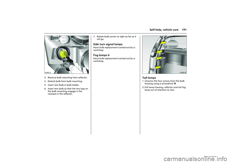
3. Remove bulb mounting from reflector.
4. Detach bulb from bulb mounting.
5. Insert new bulb in bulb holder.
6. Insert new bulb so that the two lugs on
the bulb mounting engage in the
recesses in the reflector. 7. Rotate bulb carrier to right as far as it
will go.
Side turn signal lamps Have bulb replacement carried out by a
workshop. Fog lamps
3
Have bulb replacement carried out by a
workshop.
Picture no: 17953S.tif
Tail lamps 1. Unscrew the four screws from the bulb housing using a screwdriver 3.
2. Pull lamp housing, reflector and tail fog lamp out of retainers to rear.