ECO mode OPEL MOKKA 2014 Manual user
[x] Cancel search | Manufacturer: OPEL, Model Year: 2014, Model line: MOKKA, Model: OPEL MOKKA 2014Pages: 217, PDF Size: 6 MB
Page 5 of 217

Introduction3Vehicle specific data
Please enter your vehicle's data on
the previous page to keep it easily
accessible. This information is
available in the sections "Service and maintenance" and "Technical data"
as well as on the identification plate.
Introduction
Your vehicle is a designed
combination of advanced technology, safety, environmental friendliness
and economy.
This Owner's Manual provides you
with all the necessary information to
enable you to drive your vehicle
safely and efficiently.
Make sure your passengers are
aware of the possible risk of accident
and injury which may result from
improper use of the vehicle.
You must always comply with the
specific laws and regulations of the
country that you are in. These laws
may differ from the information in this Owner's Manual.When this Owner's Manual refers to aworkshop visit, we recommend your
Opel Dealer. For gas vehicles we
recommend an Opel Repairer
authorised for servicing gas vehicles.
All Opel Dealers provide first-class service at reasonable prices.
Experienced mechanics trained by
Opel work according to specific Opel
instructions.
The customer literature pack should
always be kept ready to hand in the
vehicle.
Using this manual ■ This manual describes all options and features available for this
model. Certain descriptions,
including those for display and
menu functions, may not apply to
your vehicle due to model variant,
country specifications, special
equipment or accessories.
■ The "In brief" section will give you an initial overview.■ The table of contents at thebeginning of this manual and withineach section shows where the
information is located.
■ The index will enable you to search
for specific information.
■ This Owner's Manual depicts left- hand drive vehicles. Operation is
similar for right-hand drive vehicles.
■ The Owner's Manual uses the factory engine designations. The
corresponding sales designations
can be found in the section
"Technical data".
■ Directional data, e.g. left or right, or
front or back, always relate to thedirection of travel.
■ The vehicle display screens may not support your specific language.
■ Display messages and interior labelling are written in bold letters.
Page 19 of 217

In brief17TransmissionManual transmission
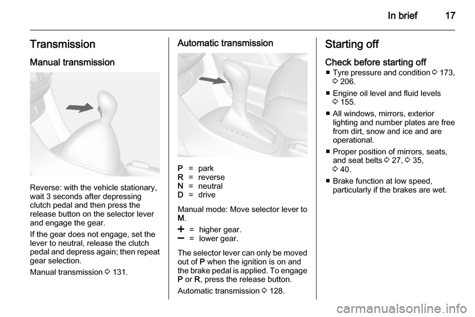
Reverse: with the vehicle stationary,
wait 3 seconds after depressing
clutch pedal and then press the
release button on the selector lever
and engage the gear.
If the gear does not engage, set the
lever to neutral, release the clutch
pedal and depress again; then repeat
gear selection.
Manual transmission 3 131.
Automatic transmissionP=parkR=reverseN=neutralD=drive
Manual mode: Move selector lever to
M .
<=higher gear.]=lower gear.
The selector lever can only be moved
out of P when the ignition is on and
the brake pedal is applied. To engage P or R, press the release button.
Automatic transmission 3 128.
Starting off
Check before starting off ■ Tyre pressure and condition 3 173,
3 206.
■ Engine oil level and fluid levels 3 155.
■ All windows, mirrors, exterior lighting and number plates are free
from dirt, snow and ice and are
operational.
■ Proper position of mirrors, seats, and seat belts 3 27, 3 35,
3 40.
■ Brake function at low speed, particularly if the brakes are wet.
Page 100 of 217

98Instruments and controls
■ Trip odometer 2
■ Average consumption 2
■ Average speed 2
■ Route guidance
Digital speed
Digital display of the instantaneous
speed.
Range
Range is calculated from current fuel
tank content and current
consumption. The display shows
average values.
After refuelling, the range is updated
automatically after a brief delay.
When the fuel level in the tank is low,
a message appears on vehicles with
Uplevel-Combi-Display.
When the tank has to be refuelled
immediately, a warning code or
warning message is displayed on
vehicles with Midlevel- and Uplevel-
Combi-Display.
Additionally the control indicator i in
the fuel gauge illuminates or flashes
3 88.
Instantaneous consumption
Display of the instantaneous
consumption.
Trip computer 1 and 2The information of two trip computers
can be reset separately for odometer, average consumption and average
speed, making it possible to display
different trip information for different
drivers.
To reset, press the SET/CLR button
in each mode for a few seconds.
Trip odometer
Trip odometer displays the recorded
distance since a certain reset.
Trip odometer counts up to a distance
of 2000 km then resets to 0.
Average consumption
Display of average consumption. The measurement can be reset at any
time and starts with a default value.
To reset, press the SET/CLR button
for a few seconds.
Page 119 of 217

Climate control117
Note
If the V button is pressed while the
engine is running, an Autostop will
be inhibited until the V button is
pressed again.
If the V button is pressed while the
engine is in an Autostop, the engine will restart automatically.
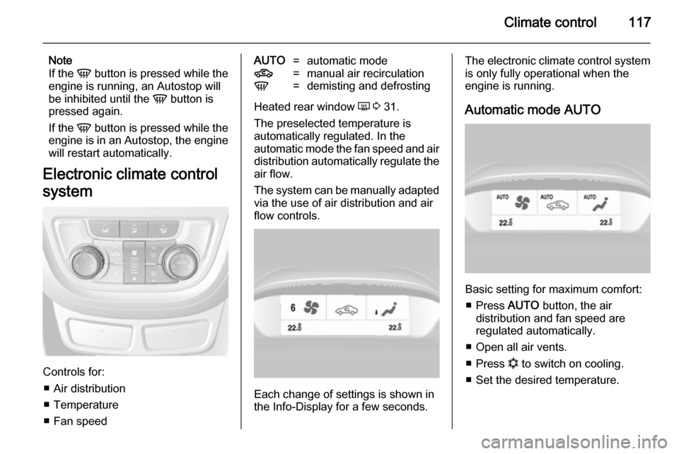
Electronic climate control
system
Controls for: ■ Air distribution
■ Temperature
■ Fan speed
AUTO=automatic mode4=manual air recirculationV=demisting and defrosting
Heated rear window Ü 3 31.
The preselected temperature is
automatically regulated. In the
automatic mode the fan speed and air distribution automatically regulate the
air flow.
The system can be manually adapted via the use of air distribution and air
flow controls.
Each change of settings is shown in
the Info-Display for a few seconds.
The electronic climate control system
is only fully operational when the
engine is running.
Automatic mode AUTO
Basic setting for maximum comfort: ■ Press AUTO button, the air
distribution and fan speed are
regulated automatically.
■ Open all air vents.
■ Press n to switch on cooling.
■ Set the desired temperature.
Page 121 of 217

Climate control119
If no cooling or drying is required,
switch off the cooling system for fuel
saving reasons. Activated cooling
might inhibit Autostops.
The display will indicate Eco when
cooling is deactivated.
Air recirculation mode 4
Press button 4 once to activate the
manual air recirculation mode.9 Warning
The exchange of fresh air is
reduced in air recirculation mode.
In operation without cooling the air humidity increases, so the
windows may mist up from inside.
The quality of the passenger
compartment air deteriorates,
which may cause the vehicle
occupants to feel drowsy.
Air conditioning with the engine
not running
When ignition is off, the residual heat or cooling in the system can be used
for climate control in passenger
compartment.
Auxiliary heater Air heater
Quickheat is an electric auxiliary air
heater which automatically warms up
the passenger compartment more
quickly.Air vents
Adjustable air vents
At least one air vent must be open
while the cooling is on.
To open the vent, turn the adjuster
wheel to the right. Adjust the air
amount at the vent outlet by turning
the adjuster wheel.
Page 153 of 217

Driving and operating151Fuel consumption - CO2-
Emissions
The values for fuel consumption
(combined) of the model Opel Mokka is within a range of 7.9 to
4.5 l/100 km.
The values for CO 2 emission
(combined) is within a range of 189 to 120 g/km.
For the values specific to your
vehicle, refer to the EEC Certificate of
Conformity provided with your vehicle or other national registration
documents.
General information The official fuel consumption and
specific CO 2 emission figures quoted
relate to the EU base model with standard equipment.
Fuel consumption data and CO 2
emission data are determined
according to regulation
R (EC) No. 715/2007 (in the latest
applicable version), taking intoconsideration the vehicle weight in
running order, as specified by the regulation.
The figures are provided only for the
purpose of comparison between
different vehicle variants and must not be taken as a guarantee for the
actual fuel consumption of a
particular vehicle. Additional
equipment may result in slightly
higher results than the stated
consumption and CO 2 figures.
Furthermore, fuel consumption is
dependent on personal driving style
as well as road and traffic conditions.Trailer hitch
General information Only use towing equipment that has
been approved for your vehicle.
Entrust retrofitting of towing
equipment to a workshop. It may be
necessary to make changes that
affect the cooling system, heat
shields or other equipment.
Fitting of towing equipment could
cover the opening of the towing eye.
If this is the case, use the coupling ball
bar for towing. Always keep the
coupling ball bar in the vehicle.
Driving characteristics and
towing tips Before attaching a trailer, lubricate
the coupling ball. However, do not do so if a stabiliser, which acts on thecoupling ball, is being used to reduce
snaking movements.
For trailers with low driving stability
and caravan trailers with a permitted
gross vehicle weight of more than
Page 178 of 217

176Vehicle care
matching process. See "TPMSSensor Matching Process" later in
this section.
■ One or more TPMS sensors are missing or damaged. The warning
message or code and the
malfunction light should go off
when the TPMS sensors are
installed and the sensor matching
process is performed successfully.
Consult your workshop for service.
■ Replacement tyres or wheels do not match the original equipment
tyres or wheels. Tyres and wheels other than those recommended
could prevent the TPMS from
functioning properly.
■ Operating electronic devices or being near facilities using radio
wave frequencies similar to the
TPMS could cause the TPMS
sensors to malfunction.
If the TPMS is not functioning
properly, it cannot detect or signal
a low tyre condition. Consult your
workshop for service if the TPMS
malfunction light and a warningmessage or code come on and stay
on.
TPMS Sensor Matching Process
Each TPMS sensor has a unique
identification code. The identification
code must be matched to a new tyre/ wheel position after rotating the tyres
or replacing one or more of the TPMS
sensors. The TPMS sensor matching
process should also be performed
after replacing a spare tyre with a
road tyre containing the TPMS
sensor.
The malfunction light and the warning message or code should go off at the
next ignition cycle. The sensors are
matched to the tyre/wheel positions,
using a TPMS relearn tool, in the
following order: driver side front tyre,
passenger side front tyre, passenger side rear tyre, and driver side rear.
Consult your workshop for service or
to purchase a relearn tool. There are
two minutes to match the first tyre/
wheel position, and five minutes
overall to match all four tyre/wheelpositions. If it takes longer, the
matching process stops and must be
restarted.
The TPMS sensor matching process
is:
1. Apply the parking brake.
2. Turn the ignition on.
3. Use the MENU button on the turn
signal lever to select the Vehicle
Information Menu in the Driver
Information Centre (DIC).
4. Use the thumbwheel to scroll to the tyre pressure menu.
5. Press the SET/CLR button to
begin the sensor matching
process. A message requesting
acceptance of the process should
display.
6. Press the SET/CLR button again
to confirm the selection. The horn sounds twice to signal the
receiver is in relearn mode.
7. Start with the driver side front tyre.
8. Place the relearn tool against the tyre sidewall, near the valve stem.
Then press the button to activate
the TPMS sensor. A horn chirp