plug OPEL MOKKA X 2017 Owner's Manual
[x] Cancel search | Manufacturer: OPEL, Model Year: 2017, Model line: MOKKA X, Model: OPEL MOKKA X 2017Pages: 247, PDF Size: 6.59 MB
Page 39 of 247

Keys, doors and windows37Roof
Sunroof9 Warning
Take care when operating the
sunroof. Risk of injury, particularly to children.
Keep a close eye on the movable parts when operating them.
Ensure that nothing becomes
trapped in them as they move.
Switch on ignition to operate the
sunroof.
Open or close
Press switch 1 or switch 2 gently to
the first detent: sunroof is opened or
closed as long as the switch is
operated.
Press switch 1 or switch 2 firmly to the
second detent and then release: the
sunroof is opened or closed
automatically with safety function
enabled. To stop movement, operate the switch once more.
Raise or close
Press switch 3 or switch 4: sunroof is
raised or closed automatically with
safety function enabled.
If the sunroof is raised, it can be
opened in one step by pressing
switch 1.
Sunblind The sunblind is operated manually.Close or open the sunblind by sliding. When the sunroof is open, the
sunblind is always open.Dirt and debris may collect on the
sunroof seal or in the track that could
cause an issue with sunroof
operation, noise or plug the water
drainage system. Periodically open
the sunroof and remove any
obstacles or loose debris. Wipe the
sunroof seal and roof sealing area
using a clean cloth, mild soap, and
water. Do not remove grease from the sunroof.
General hints
Safety function
If the sunroof encounters resistance
during automatic closing, it is
immediately stopped and opened
again.
Override safety function
In the event of closing difficulties due
to frost or the like, press and hold
switch 2. The sunroof closes without
safety function enabled. To stop
movement, release the switch.
Page 85 of 247

Instruments and controls83Power outlets
A 12 Volt power outlet is located in the
front console behind the cover. To
open, push the button.
A further 12 Volt power outlet may be
located in the rear centre console.
Do not exceed the maximum power
consumption of 120 watts.
Depending on equipment, a 230 Volt
power outlet is located in the rear
centre console.
Do not exceed the maximum power
consumption of 150 watts.
With ignition off the power outlet is
deactivated.
Additionally the power outlet is
deactivated in the event of low battery
voltage.
Electrical accessories that are
connected must comply with the
electromagnetic compatibility
requirements laid down in
DIN VDE 40 839.
Caution
Do not connect any current
delivering accessories, e.g.
electrical charging devices or
batteries.
Do not damage the outlets by
using unsuitable plugs.
Page 161 of 247

Driving and operating159If r is pressed once within an
ignition cycle, the front parking assist
is reactivated if the vehicle speed
goes below a certain value and if the
vehicle speed has not exceeded
25 km/h beforehand.
Deactivation
Deactivate the system by pressing r .
The LED in the button will go out and
Park Assist Off will be displayed in the
Driver Information Centre.
The system is deactivated
automatically at a certain speed.
Fault
In the event of a fault in the system, a vehicle message is displayed in the
Driver Information Centre.
Additionally, a vehicle message is
displayed in the Driver Information
Centre if a malfunction of the system
due to temporary conditions, e.g.
snow covered sensors is detected.
Vehicle messages 3 103.Important hints for using the
parking assist systems9 Warning
Under certain circumstances,
various reflective surfaces on
objects or clothing as well as
external noise sources may cause the system to fail to detect
obstacles.
Special attention has to be paid to
low obstacles which can damage
the lower part of the bumper. If
such obstacles leave the detection area of the sensors during
approach of the vehicle, a
continuous warning tone will
sound.
Caution
Performance of the system can be reduced when sensors are
covered, e.g. by ice or snow.
Performance of the parking assist
system can be reduced due to
heavy loading.
Special conditions apply if there
are taller vehicles in the vicinity
(e.g. off-road vehicles, mini vans,
vans). Object identification and correct distance indication in the
upper part of these vehicles
cannot be guaranteed.
Objects with a very small reflection
cross-section, e.g. objects of
narrow size or soft materials, may
not be detected by the system.
Parking assist systems do not
detect objects outside the
detection range.
Note
The parking assist system
automatically detects factory-fitted
towing equipment. It is deactivated
when the connector is plugged in.
The sensor may detect a non-
existent object (echo disturbance)
caused by external acoustic or
mechanical disturbances.
Note
The parking assist is deactivated
when the rear carrier system is
extended.
Page 176 of 247

174Driving and operatingThe permissible gross train weight
must not be exceeded. This weight is
specified on the identification plate
3 220.
Vertical coupling load The vertical coupling load is the load
exerted by the trailer on the coupling
ball. It can be varied by changing the
weight distribution when loading the
trailer.
The maximum permissible vertical
coupling load (75 kg) is specified on
the towing equipment identification
plate and in the vehicle documents.
Always aim for the maximum load,
especially in the case of heavy
trailers. The vertical coupling load
should never fall below 25 kg.
Rear axle load The permissible axle loads (see
identification plate or vehicle
documents) must not be exceeded.Towing equipmentCaution
When operating without a trailer,
remove the coupling ball bar.
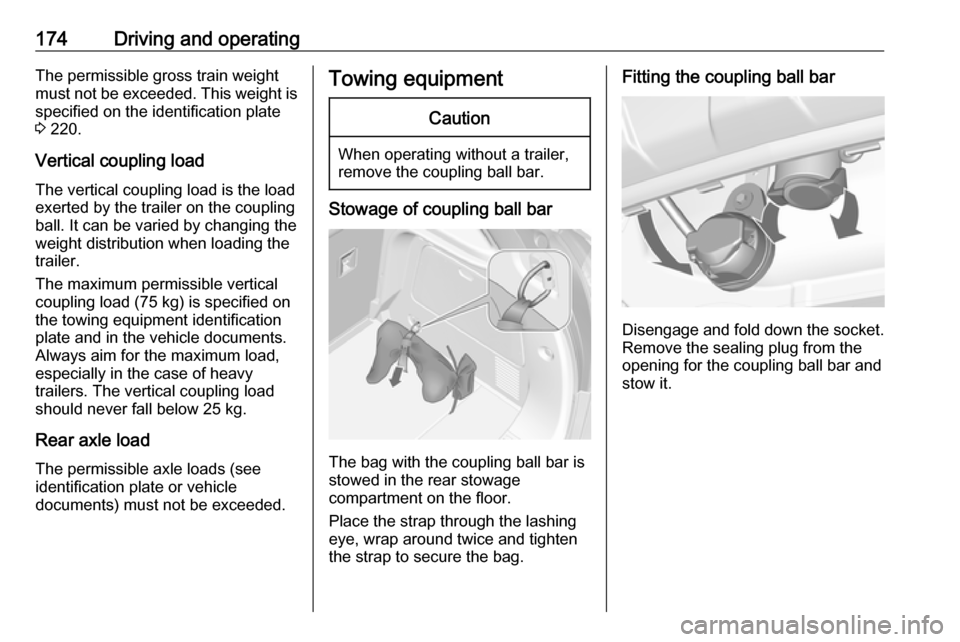
Stowage of coupling ball bar
The bag with the coupling ball bar is
stowed in the rear stowage
compartment on the floor.
Place the strap through the lashing
eye, wrap around twice and tighten
the strap to secure the bag.
Fitting the coupling ball bar
Disengage and fold down the socket. Remove the sealing plug from the
opening for the coupling ball bar and
stow it.
Page 178 of 247

176Driving and operatingAttach breakaway stopping cable to
eye.
Check that the coupling ball bar is correctly installed
● Green marking on rotary knob must point towards green
marking on coupling ball bar.
● There must be no gap between the rotary handle and the
coupling ball bar.
● The coupling ball bar must be firmly engaged in the opening.
● The coupling ball bar must be locked and the key removed.9Warning
Towing a trailer is permitted only
when a coupling ball bar is fitted correctly. If the coupling ball bardoes not engage correctly, seekthe assistance of a workshop.
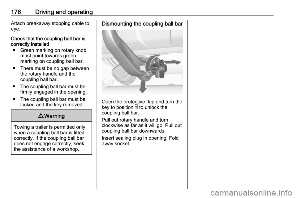
Dismounting the coupling ball bar
Open the protective flap and turn the
key to position c to unlock the
coupling ball bar.
Pull out rotary handle and turn
clockwise as far as it will go. Pull out coupling ball bar downwards.
Insert sealing plug in opening. Fold away socket.
Page 190 of 247

188Vehicle care
3.Pull the retaining rib outwards and
remove plug connector from the
bulb socket.
4. Turn the bulb holder anticlockwise
and remove it from the reflector.
5. Remove and replace the bulb socket with bulb and attach the
plug connector.
6. Insert the bulb socket into the reflector by turning clockwise and
engage.
7. Re-assemble the lining and fasten
the three torx screws.
Tail lights
The vehicle has halogen turn and lane-change signals, a back-up light
and LED tail/stop lights on the tail light
assembly.
Left-hand side
1. Disengage both covers at the respective outer side by inserting
a screwdriver. Remove both
covers and unscrew screws.
Remove the panel.
2. First disengage cover by inserting
a screwdriver at the recess. Then
disengage cover at the front and
upper side. Remove cover.
Page 194 of 247

192Vehicle careNo.Circuit33Engine control module34Horn35Air conditioning system36Front fog lamp
J-cases Fuses
No.Circuit1Electrical brake control module2Front wiper3Power module4Power terminal of instrument
panel fuse box5–6Fuel heater7Starter8Cooling fan9Cooling fanNo.Circuit10Engine control module/Glow
plug11Starter
Instrument panel fuse box
Interior fuse block is located on the
underside of the driver's side
instrument panel.
To access the fuses, remove the
storage.
To remove the storage, open and pull it.
Mini Fuses
Page 206 of 247

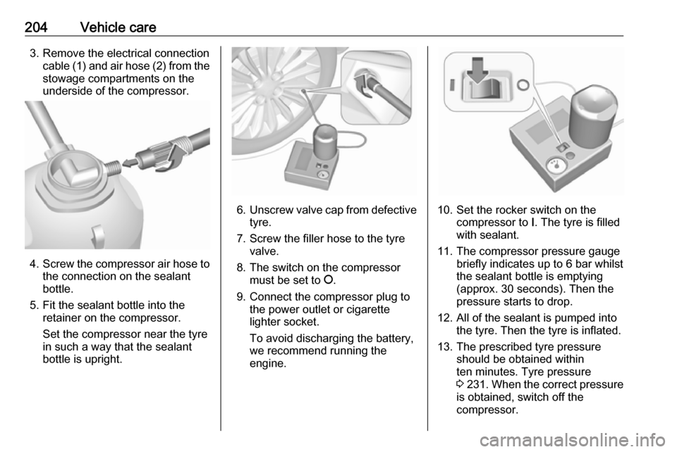
204Vehicle care3. Remove the electrical connectioncable (1) and air hose (2) from the
stowage compartments on the
underside of the compressor.
4. Screw the compressor air hose to
the connection on the sealant
bottle.
5. Fit the sealant bottle into the retainer on the compressor.
Set the compressor near the tyre
in such a way that the sealant
bottle is upright.
6. Unscrew valve cap from defective
tyre.
7. Screw the filler hose to the tyre valve.
8. The switch on the compressor must be set to J.
9. Connect the compressor plug to the power outlet or cigarette
lighter socket.
To avoid discharging the battery, we recommend running the
engine.10. Set the rocker switch on the compressor to I. The tyre is filled
with sealant.
11. The compressor pressure gauge briefly indicates up to 6 bar whilstthe sealant bottle is emptying
(approx. 30 seconds). Then the
pressure starts to drop.
12. All of the sealant is pumped into the tyre. Then the tyre is inflated.
13. The prescribed tyre pressure should be obtained within
ten minutes. Tyre pressure
3 231 . When the correct pressure
is obtained, switch off the
compressor.