lock OPEL MOKKA X 2019.5 Manual user
[x] Cancel search | Manufacturer: OPEL, Model Year: 2019.5, Model line: MOKKA X, Model: OPEL MOKKA X 2019.5Pages: 247, PDF Size: 6.86 MB
Page 187 of 247
Vehicle care1855. Install the new bulb in theheadlight assembly by turning
clockwise.
6. Reconnect the wiring harness connector.
7. Install the protective cover.
For the driver side, reinstall the
windscreen washer bottle filler neck
by firmly pushing it straight into the
bottle. Ensure that the filler neck clip
engages into the underhood electrical
centre retainer.
Uplevel headlight assembly
The uplevel model vehicle has LED high beam and low beam headlights,
turn lights, a sidelight and daytime
running lights on the headlight
assembly.Front fog lights
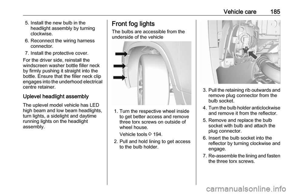
The bulbs are accessible from the
underside of the vehicle
1. Turn the respective wheel inside to get better access and remove
three torx screws on outside of
wheel house.
Vehicle tools 3 194.
2. Pull and hold lining to get access to the bulb holder.
3.Pull the retaining rib outwards and
remove plug connector from the
bulb socket.
4. Turn the bulb holder anticlockwise
and remove it from the reflector.
5. Remove and replace the bulb socket with bulb and attach the
plug connector.
6. Insert the bulb socket into the reflector by turning clockwise and
engage.
7. Re-assemble the lining and fasten
the three torx screws.
Page 189 of 247
Vehicle care187
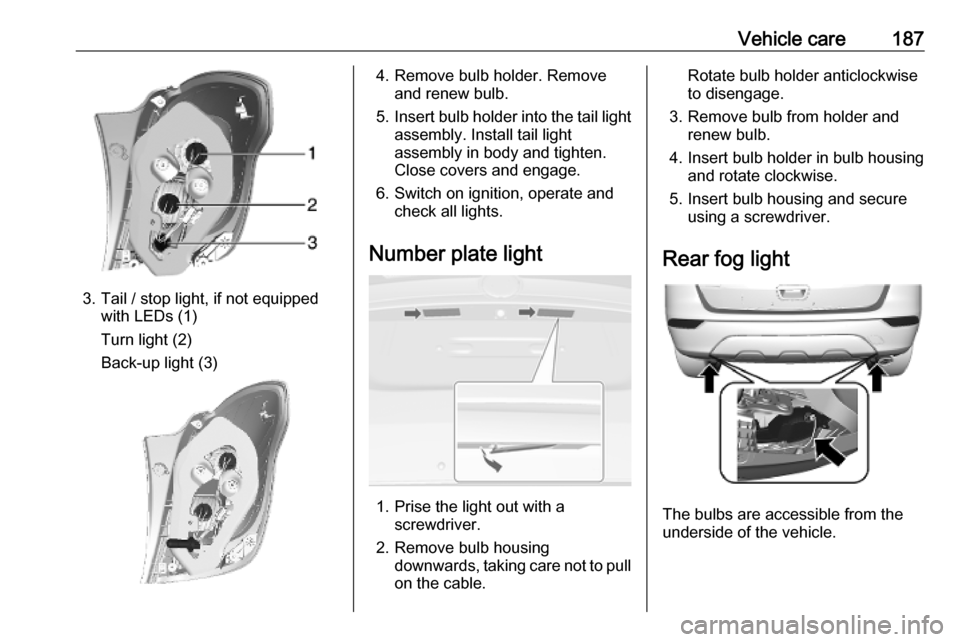
3. Tail / stop light, if not equippedwith LEDs (1)
Turn light (2)
Back-up light (3)
4. Remove bulb holder. Remove and renew bulb.
5. Insert bulb holder into the tail light
assembly. Install tail light
assembly in body and tighten.
Close covers and engage.
6. Switch on ignition, operate and check all lights.
Number plate light
1. Prise the light out with a screwdriver.
2. Remove bulb housing downwards, taking care not to pull
on the cable.
Rotate bulb holder anticlockwise
to disengage.
3. Remove bulb from holder and renew bulb.
4. Insert bulb holder in bulb housing and rotate clockwise.
5. Insert bulb housing and secure using a screwdriver.
Rear fog light
The bulbs are accessible from the
underside of the vehicle.
Page 190 of 247
188Vehicle care
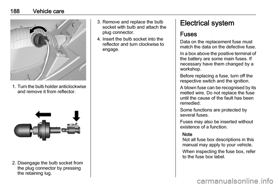
1.Turn the bulb holder anticlockwise
and remove it from reflector.
2. Disengage the bulb socket from the plug connector by pressing
the retaining lug.
3. Remove and replace the bulb socket with bulb and attach the
plug connector.
4. Insert the bulb socket into the reflector and turn clockwise to
engage.Electrical system
Fuses
Data on the replacement fuse must
match the data on the defective fuse.
In a box above the positive terminal of
the battery are some main fuses. If
necessary have them changed by a workshop.
Before replacing a fuse, turn off the
respective switch and the ignition.
A blown fuse can be recognised by its melted wire. Do not replace the fuse
until the cause of the fault has been
remedied.
Some functions are protected by
several fuses.
Fuses may also be inserted without existence of a function.
Note
Not all fuse box descriptions in this
manual may apply to your vehicle.
When inspecting the fuse box, refer
to the fuse box label.
Page 191 of 247
Vehicle care189Fuse extractorA fuse extractor may be located in the fuse box in the engine compartment.
Place the fuse extractor on the
various types of use from the top or
side, and withdraw fuse.
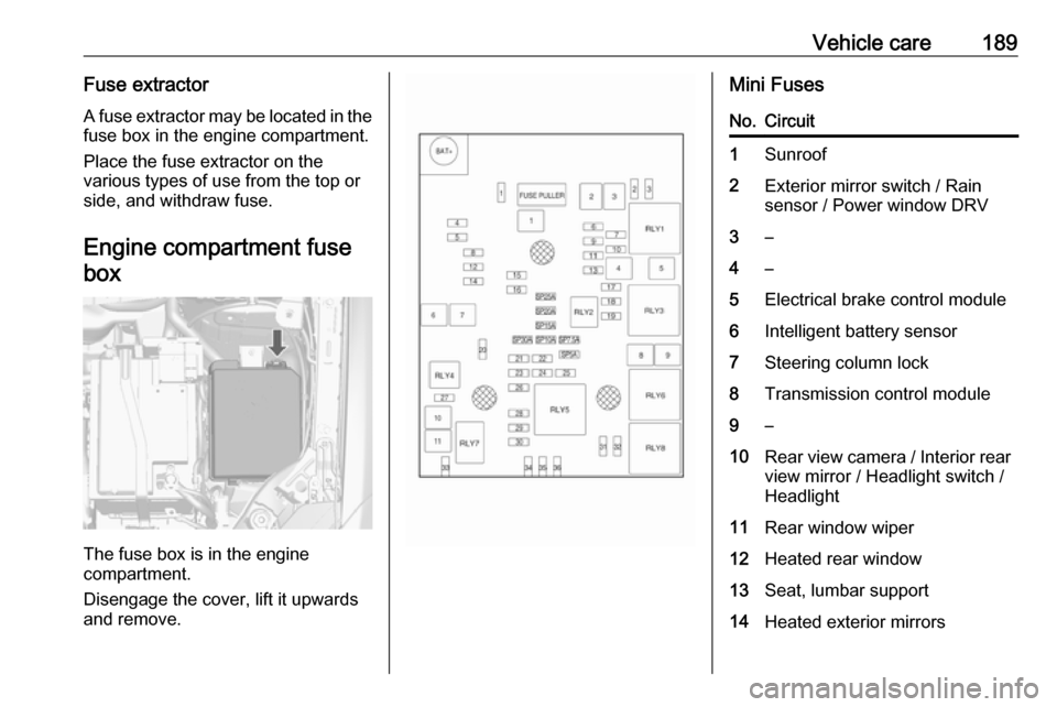
Engine compartment fusebox
The fuse box is in the engine
compartment.
Disengage the cover, lift it upwards
and remove.
Mini FusesNo.Circuit1Sunroof2Exterior mirror switch / Rain
sensor / Power window DRV3–4–5Electrical brake control module6Intelligent battery sensor7Steering column lock8Transmission control module9–10Rear view camera / Interior rear
view mirror / Headlight switch /
Headlight11Rear window wiper12Heated rear window13Seat, lumbar support14Heated exterior mirrors
Page 194 of 247
192Vehicle careNo.Circuit16Adaptive forward lighting17Column lock18Ultrasonic park assist module19Body control module / Regu‐
lated voltage control20Steering wheel21–22Cigarette lighter / DC accessory power outlet (front)23Cigarette lighter / DC accessory
power outlet (rear center
console)24Spare25Telematics service module26Heated steering wheel27Instrument panel cluster / Info‐
tainment system / Auxiliary
heater switch28Trailer socketNo.Circuit29Info Display / Infotainment
system30Transmission control module31Instrument panel cluster32Infotainment system33Trailer socket34Passive entry / Passive start
module
S/B Fuses
No.Circuit01Power seat switch02Spare03Power windows front04Power windows rear05Logistic mode06Power seat switchNo.Circuit07Spare08Spare
Midi Fuse
No.CircuitM01PTC
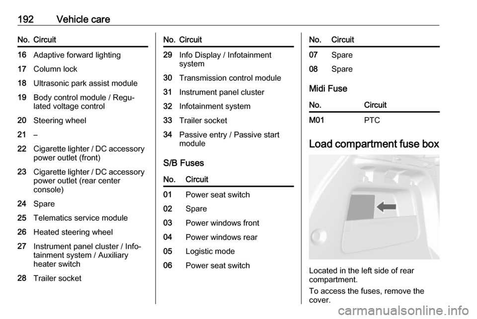
Load compartment fuse box
Located in the left side of rear
compartment.
To access the fuses, remove the cover.
Page 203 of 247

Vehicle care201Changing tyre and wheelsize
If tyres of a different size than those
fitted at the factory are used, it may be necessary to reprogramme the
nominal tyre pressure and make
other vehicle modifications.
After converting to a different tyre
size, have the label with tyre
pressures replaced and the tyre
pressure monitoring system
reinitialised. 3 1969 Warning
The use of unsuitable tyres or
wheels may lead to accidents and will invalidate the vehicle
operating permit.
Wheel covers
Wheel covers and tyres that are
factory-approved for the respective
vehicle and comply with all of the
relevant wheel and tyre combination requirements must be used.
If the wheel covers and tyres used are
not factory-approved, the tyres must
not have a rim protection ridge.
Wheel covers must not impair brake
cooling.9 Warning
Use of unsuitable tyres or wheel
covers could lead to sudden
pressure loss and thereby
accidents.
Vehicles with alloy wheels: When
mounting steel wheels with alloy
wheel nuts, e.g. when changing to
winter tyres, the wheel covers cannot
be attached to the steel wheels.
Tyre chains
Use tyre chains only on front wheels.
9 Warning
Damage may lead to tyre blowout.
Tyre chains are permitted on tyres of
size 215/65 R16, 215/60 R17 and
215/55 R18.
On tyres of size 215/65 R16 and
215/60 R17 always use fine mesh
chains suitable for sport utility
vehicles that add no more than
9 mm to the tyre tread and the inboard sides (including chain lock).
Page 212 of 247

210Vehicle care● Apply the parking brake,transmission in neutral,
automatic transmission in P.
● Open the positive terminal protection caps of both batteries.
Lead connection order:
1. Connect the red lead to the positive terminal of the booster
battery.
2. Connect the other end of the red lead to the positive terminal of the
discharged battery.
3. Connect the black lead to the negative terminal of the booster
battery.
4. Connect the other end of the black
lead to a vehicle grounding point,
such as the engine block or an
engine mounting bolt. Connect as far away from the discharged
battery as possible, however at
least 60 cm.
Route the leads so that they cannot
catch on rotating parts in the engine
compartment.
To start the engine: 1. Start the engine of the vehicle providing the jump.
2. After 5 min, start the other engine.
Start attempts should be made for
no longer than 15 s at an interval
of 1 min.
3. Allow both engines to idle for approx. three minutes with the
leads connected.4. Switch on electrical consumers (e.g. headlights, heated rear
window) of the vehicle receiving
the jump start.
5. Reverse above sequence exactly when removing leads.
Page 213 of 247

Vehicle care211Towing
Towing the vehicle
Wrap a cloth around the tip of a flat
screwdriver to prevent paint damage.
Insert the screwdriver in the slot at the
lower part of the cap. Release the cap by carefully moving the screwdriver
downwards.
The towing eye is stowed with the
vehicle tools 3 194.
Screw in the towing eye as far as it will
go until it stops in a horizontal
position.
Attach a tow rope – or better still a tow
rod – to the towing eye.
The towing eye must only be used for
towing and not for recovering the
vehicle.
Switch on ignition to release steering wheel lock and to permit operation of
brake lights, horn and windscreen
wiper.
Switch the selector lever to neutral.
Release the parking brake.
Caution
Never tow a vehicle equipped with All Wheel Drive (AWD) with the
front or rear tyres on the road. If
you tow a vehicle equipped with
AWD while the front or rear tyres
are rolling on the road, the drive
system in the vehicle could be
severely damaged. When towing
vehicles equipped with AWD, all
four tyres must not be in contact
with the road.
Caution
Drive slowly. Do not drive jerkily.
Excessive tractive force can
damage the vehicle.
When the engine is not running,
considerably more force is needed to
brake and steer.
To prevent the entry of exhaust gases from the towing vehicle, switch on the
air recirculation system 3 123 and
close the windows.
Page 215 of 247
Vehicle care213Caution
Drive slowly. Do not drive jerkily.
Excessive tractive force can
damage the vehicle.
After towing, unscrew the towing eye.
Insert cap at the bottom and engage
cap.
Appearance care
Exterior care
Locks The locks are lubricated at the factoryusing a high quality lock cylinder
grease. Use de-icing agent only when
absolutely necessary, as this has a
degreasing effect and impairs lock function. After using a de-icing agent, have the locks regreased by a
workshop.
Washing The paintwork of your vehicle is
exposed to environmental influences. Wash and wax your vehicle regularly.
When using automatic vehicle
washes, select a programme that
includes waxing.
Bird droppings, dead insects, resin,
pollen and the like should be cleaned
off immediately, as they contain
aggressive constituents which can
cause paint damage.If using a vehicle wash, comply with
the vehicle wash manufacturer's
instructions. The windscreen wiper
and rear window wiper must be
switched off. Remove antenna and
external accessories such as roof
racks etc.
If you wash your vehicle by hand,
make sure that the insides of the
wheel housings are also thoroughly
rinsed out.
Clean edges and folds on opened
doors and the bonnet as well as the
areas they cover.Caution
Always use a cleaning agent with
a pH value of 4 to 9.
Do not use cleaning agents on hot surfaces.
Have the door hinges of all doors
greased by a workshop.
Do not clean the engine compartment with a steam-jet or high-pressure jet
cleaner.
Page 241 of 247

Customer information239processing and use of personal data
for the purposes of preparation of services take place solely on the
basis of legal permission, e.g. in the
case of a legally prescribed
emergency communication system or
a contractual agreement, or by virtue
of consent.
You can activate or deactivate the services and functions (which are
subject to charges to some extent)
and, in some cases, the vehicle's
entire radio network connection. This
does not include statutory functions
and services such as an emergency
communication system.
Third party services
If you make use of online services
from other providers (third parties),
these services are subject to the
liability and data protection and usage conditions of the provider in question.
The manufacturer frequently has no
influence over the content exchanged
in this regard.Therefore, please note the nature,
scope and purpose of the collection
and use of personal data within the
scope of third party services provided by the service provider in question.
Radio Frequency
Identification (RFID)
RFID technology is used in some
vehicles for functions such as tyre
pressure monitoring and immobiliser.
It is also used in connection with
conveniences such as radio remote
controls for door locking/unlocking
and starting. RFID technology in Opel vehicles does not use or record
personal information or link with any other Opel system containing
personal information.