wheel OPEL MOVANO_B 2017.5 Manual user
[x] Cancel search | Manufacturer: OPEL, Model Year: 2017.5, Model line: MOVANO_B, Model: OPEL MOVANO_B 2017.5Pages: 261, PDF Size: 6.26 MB
Page 11 of 261
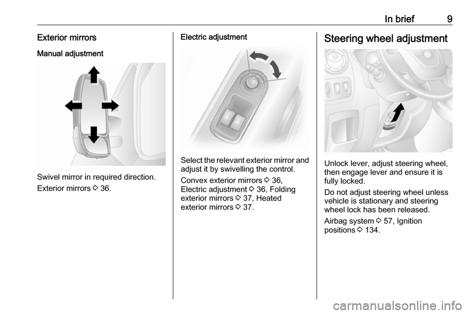
In brief9Exterior mirrorsManual adjustment
Swivel mirror in required direction.
Exterior mirrors 3 36.
Electric adjustment
Select the relevant exterior mirror and
adjust it by swivelling the control.
Convex exterior mirrors 3 36,
Electric adjustment 3 36, Folding
exterior mirrors 3 37, Heated
exterior mirrors 3 37.
Steering wheel adjustment
Unlock lever, adjust steering wheel,
then engage lever and ensure it is fully locked.
Do not adjust steering wheel unless
vehicle is stationary and steering
wheel lock has been released.
Airbag system 3 57, Ignition
positions 3 134.
Page 13 of 261

In brief111Fixed air vents .................... 130
2 Headlight range
adjustment ......................... 110
Ultrasonic parking assist .....163
Traction control system ......156
Electronic Stability
Program ............................. 157
3 Side air vents .....................129
4 Light switch ........................ 108
Turn and lane-change
signals ................................ 111
High beam and low beam,
headlight flash ....................109
Sidelights ............................ 108
Automatic light control .......108
Exit lighting ......................... 115
Front fog lights ...................112
Rear fog light ...................... 112
High beam assist ................109
5 Instruments .......................... 89
Transmission display ............93Driver Information Centre .... 102
Trip computer ...................... 104
6 Horn ..................................... 84
Driver airbag ........................ 60
7 Remote control on
steering wheel .......................84
Cruise control .....................159
8 Windscreen wiper,
windscreen washer system ..85
Trip computer ...................... 104
9 Coin tray ............................... 72
10 Power outlet, USB slot ..........87
11 Centre air vents .................. 129
12 Storage compartment ...........72
13 Info-display .......................... 102
14 Front passenger airbag .........60
15 Storage compartment ..........72
16 Glovebox .............................. 73
17 Seat belt reminder ................. 96
Front passenger airbag
deactivation ........................... 61
18 Cupholders ........................... 7319Climate control system ....... 116
Electronic climate control
system ................................. 118
20 Cigarette lighter .................... 89
Power outlet ......................... 87
21 Gear lever, Manual
transmission ........................ 150
Manual transmission
automated ........................... 150
22 Cruise control and speed
limiter ................................. 159
Manual transmission
automated,
Winter and Laden modes ....152
Idle speed control ...............136
Stop-start system ................136
ECO mode .......................... 133
23 Ignition switch with
steering wheel lock ............134
24 Steering column controls .....84
25 Steering wheel adjustment ..84
26 Bonnet release lever ..........176
27 Auxiliary heater ...................123
Page 20 of 261
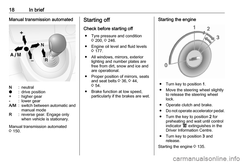
18In briefManual transmission automatedN:neutralo:drive position+:higher gear-:lower gearA/M:switch between automatic and
manual modeR:reverse gear. Engage only
when vehicle is stationary.
Manual transmission automated
3 150.
Starting off
Check before starting off ● Tyre pressure and condition 3 200, 3 246.
● Engine oil level and fluid levels 3 177.
● All windows, mirrors, exterior lighting and number plates are
free from dirt, snow and ice and
are operational.
● Proper position of mirrors, seats and seat belts 3 36, 3 44,
3 54.
● Brake function at low speed, particularly if the brakes are wet.Starting the engine
● Turn key to position 1.
● Move the steering wheel slightly to release the steering wheel
lock.
● Operate clutch and brake.
● Do not operate accelerator pedal.
● Turn the key to position 2 for
preheating and wait until control
indicator ! extinguishes in the
Driver Information Centre.
● Turn key to position 3 and
release.
Starting the engine 3 135.
Page 21 of 261
In brief19Stop-start system
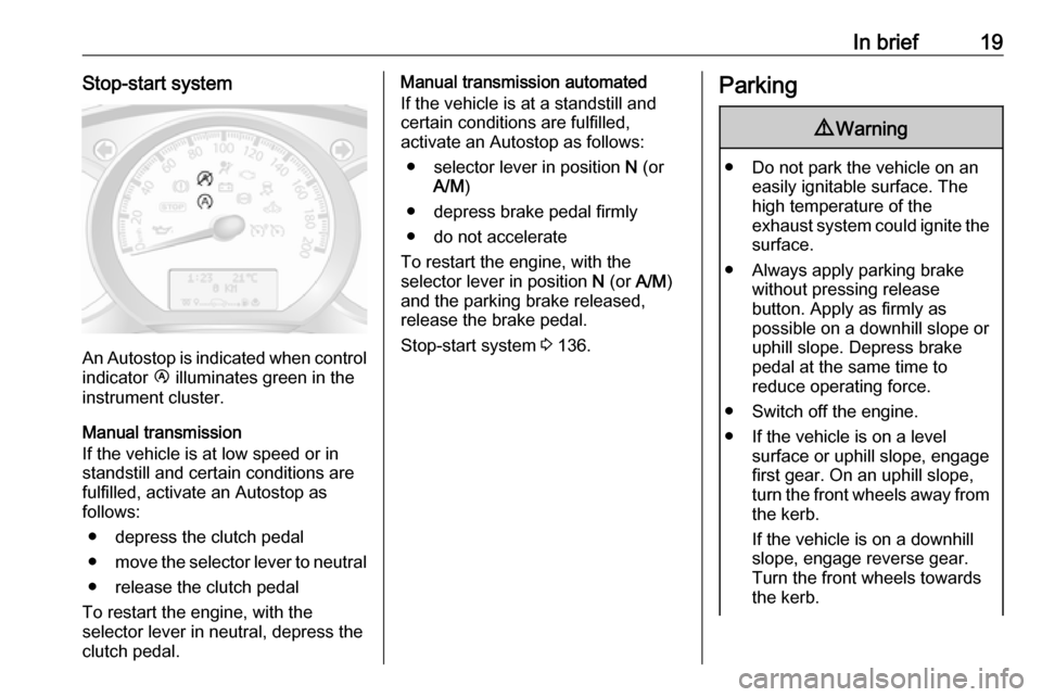
An Autostop is indicated when controlindicator Ï illuminates green in the
instrument cluster.
Manual transmission If the vehicle is at low speed or in
standstill and certain conditions are
fulfilled, activate an Autostop as
follows:
● depress the clutch pedal● move the selector lever to neutral
● release the clutch pedal
To restart the engine, with the
selector lever in neutral, depress the
clutch pedal.
Manual transmission automated
If the vehicle is at a standstill and
certain conditions are fulfilled,
activate an Autostop as follows:
● selector lever in position N (or
A/M )
● depress brake pedal firmly
● do not accelerate
To restart the engine, with the
selector lever in position N (or A/M)
and the parking brake released,
release the brake pedal.
Stop-start system 3 136.Parking9 Warning
● Do not park the vehicle on an
easily ignitable surface. The
high temperature of the
exhaust system could ignite the
surface.
● Always apply parking brake without pressing release
button. Apply as firmly as
possible on a downhill slope or
uphill slope. Depress brake
pedal at the same time to
reduce operating force.
● Switch off the engine.
● If the vehicle is on a level surface or uphill slope, engage
first gear. On an uphill slope,
turn the front wheels away from
the kerb.
If the vehicle is on a downhill
slope, engage reverse gear.
Turn the front wheels towards the kerb.
Page 22 of 261

20In brief● Close the windows.
● Remove the ignition key from the ignition switch. Turn the
steering wheel until the
steering wheel lock is felt to
engage.
● Lock the vehicle by pressing e on
the remote control 3 24.
● Activate the anti-theft alarm system 3 34.
● The engine cooling fans may run
after the engine has been
switched off 3 176.
Caution
After running at high engine
speeds or with high engine loads,
operate the engine briefly at a low load or run in neutral for approx.30 seconds before switching off, in
order to protect the turbocharger.
Keys, locks 3 21, Laying the vehicle
up for a long period of time 3 175.
Page 34 of 261

32Keys, doors and windows
The indicator illuminates during
operation of the power side step. If it
remains illuminated with the door closed, the step has not retracted, or
the door has not fully latched into its
locking position.
In the event of a failure, manually retract the power side step by
unscrewing the orange handwheel
located at the rear of the step,
ensuring that there are no obstacles
preventing closure. When the step is
retracted, screw in the orange
handwheel. Seek the assistance of a
workshop.
Rear doors
Lock and unlock the rear doors with
the remote control or key (if
equipped).
Central locking system 3 24, Manual
door locks 3 23.
To open the right-hand rear door, pull
the exterior handle.
The right-hand door can also be
opened from inside the vehicle by
pulling the interior handle.
The left-hand rear door is then
released using the lever.
9 Warning
The rear lights may be obscured if
the rear doors are open and the
vehicle is parked on the roadside.
Make other road users aware of the vehicle, by using a warning
triangle or other equipment
specified in the road traffic
regulations.
The doors are retained in the 90º
position by locking stays.
Page 46 of 261
44Seats, restraintsDepending on version, head
restraints can also be tilted forwards
or backwards. Push or pull the lower
part of the head restraint to adjust.
Note
Approved accessories may only be
attached to the front passenger seat head restraint if the seat is not in use.
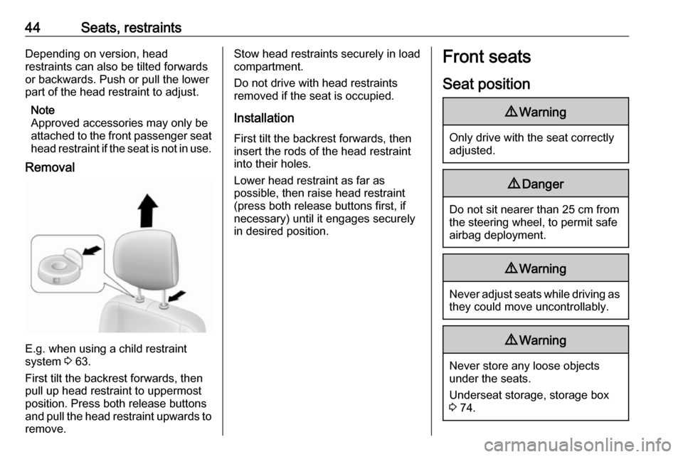
Removal
E.g. when using a child restraint
system 3 63.
First tilt the backrest forwards, then
pull up head restraint to uppermost
position. Press both release buttons
and pull the head restraint upwards to remove.
Stow head restraints securely in load
compartment.
Do not drive with head restraints
removed if the seat is occupied.
Installation First tilt the backrest forwards, then
insert the rods of the head restraint into their holes.
Lower head restraint as far as
possible, then raise head restraint (press both release buttons first, if
necessary) until it engages securely
in desired position.Front seats
Seat position9 Warning
Only drive with the seat correctly
adjusted.
9 Danger
Do not sit nearer than 25 cm from
the steering wheel, to permit safe
airbag deployment.
9 Warning
Never adjust seats while driving as
they could move uncontrollably.
9 Warning
Never store any loose objects
under the seats.
Underseat storage, storage box 3 74.
Page 47 of 261
Seats, restraints45
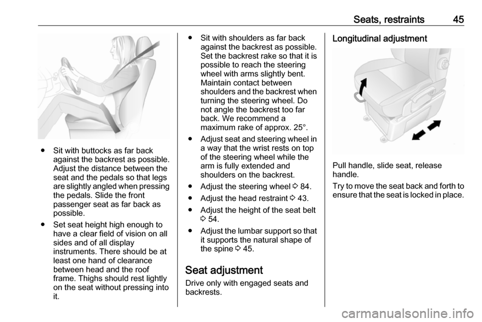
● Sit with buttocks as far backagainst the backrest as possible.
Adjust the distance between the
seat and the pedals so that legs
are slightly angled when pressing
the pedals. Slide the front
passenger seat as far back as
possible.
● Set seat height high enough to have a clear field of vision on allsides and of all display
instruments. There should be at
least one hand of clearance
between head and the roof
frame. Thighs should rest lightly
on the seat without pressing into
it.
● Sit with shoulders as far back against the backrest as possible.Set the backrest rake so that it is
possible to reach the steering
wheel with arms slightly bent.
Maintain contact between
shoulders and the backrest when turning the steering wheel. Do
not angle the backrest too far
back. We recommend a
maximum rake of approx. 25°.
● Adjust seat and steering wheel in
a way that the wrist rests on top
of the steering wheel while the
arm is fully extended and
shoulders on the backrest.
● Adjust the steering wheel 3 84.
● Adjust the head restraint 3 43.
● Adjust the height of the seat belt 3 54.
● Adjust the lumbar support so that
it supports the natural shape of
the spine 3 45.
Seat adjustment Drive only with engaged seats and
backrests.Longitudinal adjustment
Pull handle, slide seat, release
handle.
Try to move the seat back and forth to ensure that the seat is locked in place.
Page 49 of 261
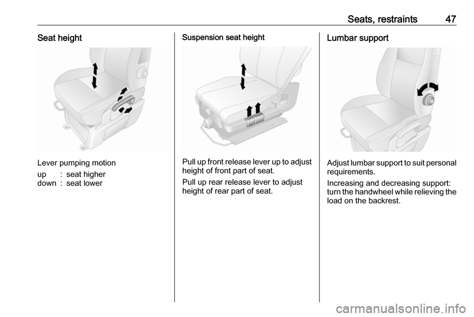
Seats, restraints47Seat height
Lever pumping motion
up:seat higherdown:seat lowerSuspension seat height
Pull up front release lever up to adjustheight of front part of seat.
Pull up rear release lever to adjust height of rear part of seat.
Lumbar support
Adjust lumbar support to suit personal requirements.
Increasing and decreasing support:
turn the handwheel while relieving the load on the backrest.
Page 59 of 261
Seats, restraints579Warning
The lap belt must be positioned as
low as possible across the pelvis
to prevent pressure on the
abdomen.
Airbag system
The airbag system consists of a
number of individual systems
depending on the scope of
equipment.
When triggered the airbags inflate
within milliseconds. They also deflate
so quickly that it is often unnoticeable
during the collision.9 Warning
If handled improperly the airbag
systems can be triggered in an
explosive manner.
Note
The airbag systems and belt
pretensioner control electronics are
located in the centre console area.
Do not put any magnetic objects in
this area.
Do not fix any objects onto the airbag
covers and do not cover them with
other materials.
Each airbag is triggered only once.
Have deployed airbags replaced by
a workshop. Furthermore, it may be
necessary to have the steering
wheel, the instrument panel, parts of the panelling, the door seals,
handles and the seats replaced.
Do not make any modifications to
the airbag system as this will
invalidate the vehicle type approval.
When the airbags inflate escaping hot gases may cause burns.
Control indicator v for airbag systems
3 96.
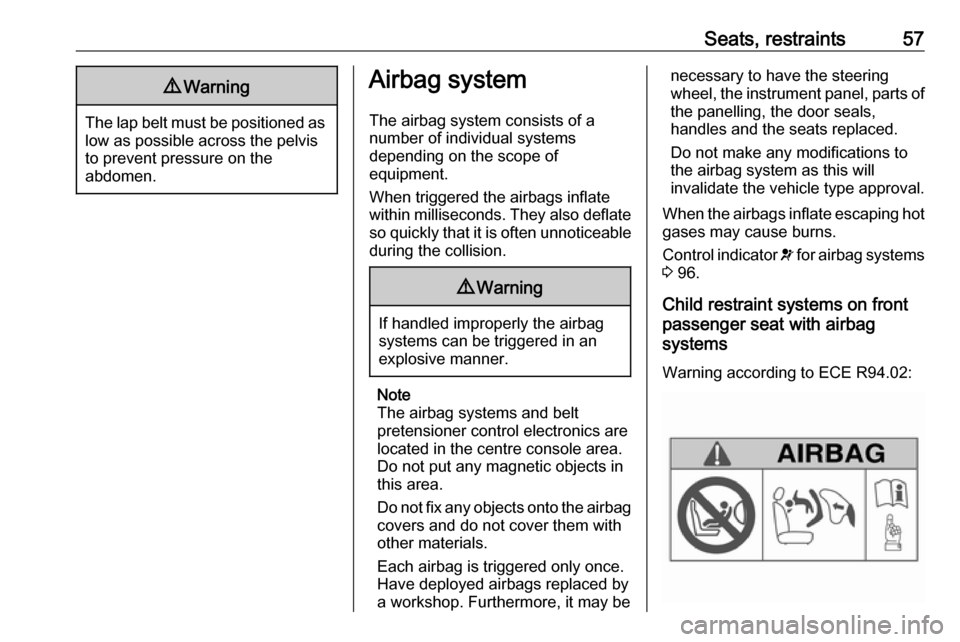
Child restraint systems on front
passenger seat with airbag
systems
Warning according to ECE R94.02: