fuse OPEL MOVANO_B 2017 Manual user
[x] Cancel search | Manufacturer: OPEL, Model Year: 2017, Model line: MOVANO_B, Model: OPEL MOVANO_B 2017Pages: 255, PDF Size: 6.12 MB
Page 14 of 255

12In brief28Storage compartment ..........70
Fuse box ............................ 189
Page 94 of 255
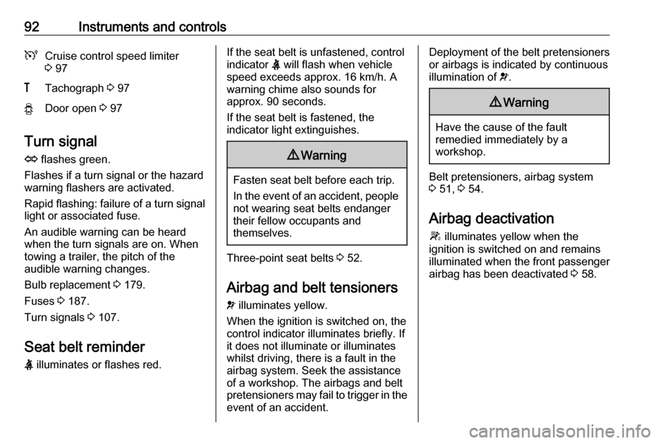
92Instruments and controlsUCruise control speed limiter
3 97&Tachograph 3 97yDoor open 3 97
Turn signal
O flashes green.
Flashes if a turn signal or the hazard
warning flashers are activated.
Rapid flashing: failure of a turn signal
light or associated fuse.
An audible warning can be heard
when the turn signals are on. When
towing a trailer, the pitch of the
audible warning changes.
Bulb replacement 3 179.
Fuses 3 187.
Turn signals 3 107.
Seat belt reminder
X illuminates or flashes red.
If the seat belt is unfastened, control
indicator X will flash when vehicle
speed exceeds approx. 16 km/h. A warning chime also sounds for
approx. 90 seconds.
If the seat belt is fastened, the
indicator light extinguishes.9 Warning
Fasten seat belt before each trip.
In the event of an accident, people
not wearing seat belts endanger their fellow occupants and
themselves.
Three-point seat belts 3 52.
Airbag and belt tensioners
v illuminates yellow.
When the ignition is switched on, the control indicator illuminates briefly. If
it does not illuminate or illuminates
whilst driving, there is a fault in the
airbag system. Seek the assistance
of a workshop. The airbags and belt
pretensioners may fail to trigger in the event of an accident.
Deployment of the belt pretensioners
or airbags is indicated by continuous
illumination of v.9 Warning
Have the cause of the fault
remedied immediately by a
workshop.
Belt pretensioners, airbag system
3 51, 3 54.
Airbag deactivation
W illuminates yellow when the
ignition is switched on and remains
illuminated when the front passenger
airbag has been deactivated 3 58.
Page 123 of 255
Climate control121Teach remote control (Type A)
If the vehicle battery is reconnected, the LED in the instrument panel
button illuminates and the system
configures the remote control menu
automatically. If the LED flashes,
press OK on remote control, select
Add or AddE and confirm.
Additional remote control units may
also be configured. Press the button
until LED flashes, switch on the
remote control, select Add and
confirm.
AddE teaches the current remote
control unit exclusively and blocks all
previously configured units. Add
teaches up to four remote control
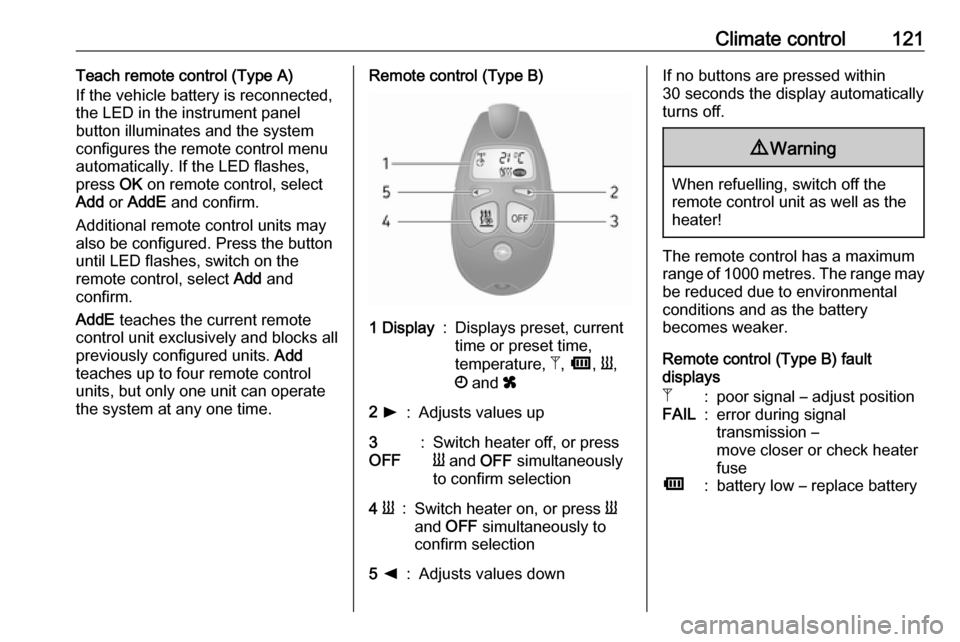
units, but only one unit can operate the system at any one time.Remote control (Type B)1 Display:Displays preset, current
time or preset time,
temperature, Z, Ü , Y ,
Ö and x2 l:Adjusts values up3
OFF:Switch heater off, or press
Y and OFF simultaneously
to confirm selection4 Y:Switch heater on, or press Y
and OFF simultaneously to
confirm selection5 k:Adjusts values downIf no buttons are pressed within
30 seconds the display automatically
turns off.9 Warning
When refuelling, switch off the
remote control unit as well as the
heater!
The remote control has a maximum
range of 1000 metres. The range may
be reduced due to environmental
conditions and as the battery
becomes weaker.
Remote control (Type B) fault
displays
Z:poor signal – adjust positionFAIL:error during signal
transmission –
move closer or check heater
fuseÜ:battery low – replace battery
Page 124 of 255
122Climate controlTeach remote control (Type B)
Up to four additional remote control
units may also be configured. During
additional teaching processes, the
oldest transmitter will be deleted each
time.
Remove the heater fuse for
five seconds, then refit the fuse.
Within two - six seconds press OFF
for one second. Teaching is
completed.
If the remote has not been used for a long period, press the OFF button six
times at intervals of two seconds,
then press and hold for another
two seconds, then wait two minutes.Manual control
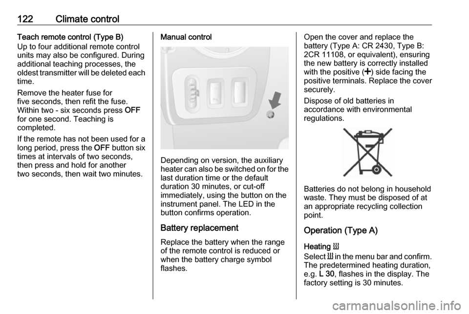
Depending on version, the auxiliary
heater can also be switched on for the
last duration time or the default
duration 30 minutes, or cut-off
immediately, using the button on the
instrument panel. The LED in the
button confirms operation.
Battery replacement
Replace the battery when the range
of the remote control is reduced or
when the battery charge symbol
flashes.
Open the cover and replace the
battery (Type A: CR 2430, Type B:
2CR 11108, or equivalent), ensuring
the new battery is correctly installed
with the positive ( <) side facing the
positive terminals. Replace the cover
securely.
Dispose of old batteries in
accordance with environmental
regulations.
Batteries do not belong in household
waste. They must be disposed of at
an appropriate recycling collection
point.
Operation (Type A)
Heating Y
Select Y in the menu bar and confirm.
The predetermined heating duration,
e.g. L 30, flashes in the display. The
factory setting is 30 minutes.
Page 171 of 255

Vehicle care169Vehicle careGeneral Information...................170
Accessories and vehicle modifications .......................... 170
Vehicle storage ........................170
End-of-life vehicle recovery .....171
Vehicle checks ........................... 171
Performing work ......................171
Bonnet ..................................... 171
Engine oil ................................. 172
Engine coolant ......................... 173
Power steering fluid .................174
Washer fluid ............................ 175
Brakes ..................................... 175
Brake fluid ............................... 175
Vehicle battery ......................... 175
Diesel fuel filter ........................178
Diesel fuel system bleeding .....178
Wiper blade replacement ........179
Bulb replacement .......................179
Headlights ............................... 179
Adaptive forward lighting .........182
Fog lights ................................. 182
Front turn signal lights .............182
Tail lights ................................. 183
Side turn signal lights ..............184Centre high-mounted brake
light ......................................... 185
Number plate light ...................185
Interior lights ............................ 186
Instrument panel illumination ...187
Electrical system ........................187
Fuses ....................................... 187
Engine compartment fuse box . 188
Instrument panel fuse box .......189
Load compartment fuse box ....190
Vehicle tools .............................. 192
Tools ........................................ 192
Wheels and tyres .......................193
Tyres ....................................... 193
Winter tyres ............................. 193
Tyre designations ....................193
Tyre pressure .......................... 193
Tyre pressure monitoring system .................................... 194
Tread depth ............................. 196
Changing tyre and wheel size . 197 Wheel covers ........................... 197
Tyre chains .............................. 197
Tyre repair kit .......................... 198
Wheel changing .......................201
Spare wheel ............................ 203
Jump starting ............................. 206Towing....................................... 208
Towing the vehicle ...................208
Towing another vehicle ...........209
Appearance care .......................209
Exterior care ............................ 209
Interior care ............................. 211
Page 189 of 255
Vehicle care187Instrument panel
illumination
Have bulbs replaced by a workshop.Electrical system
Fuses Data on the replacement fuse must
match the data on the defective fuse.
There are two fuse boxes in the
vehicle:
● on the left-hand side of the instrument panel, behind the trim
panel
● in the engine compartment located below the coolant
expansion tankCombi
An additional fuse box is located
behind a trim panel on the right-hand
side of the load compartment, beside the rear door.Bus
An additional fuse box is located on
the lower right-hand side of the load
compartment, below the step trim
panel.
Before replacing a fuse, turn off the
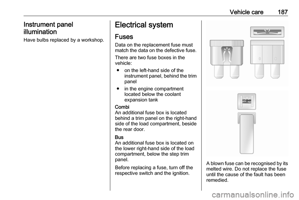
respective switch and the ignition.A blown fuse can be recognised by its melted wire. Do not replace the fuse
until the cause of the fault has been
remedied.
Page 190 of 255
188Vehicle careIt is advisable to carry a full set of
fuses. Consult a workshop.
Some functions are protected by
several fuses.
Fuses may also be inserted without
existence of a function.
Note
Not all fuse box descriptions in this
manual may apply to your vehicle.
When inspecting the fuse box, refer to the fuse box label.
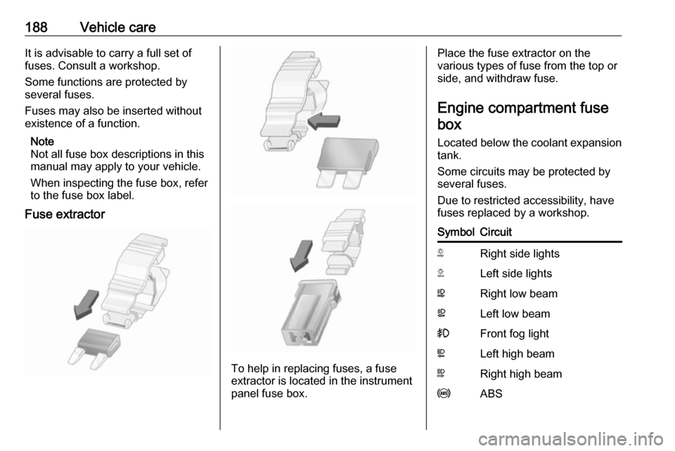
Fuse extractor
To help in replacing fuses, a fuse
extractor is located in the instrument
panel fuse box.
Place the fuse extractor on the
various types of fuse from the top or
side, and withdraw fuse.
Engine compartment fusebox
Located below the coolant expansion tank.
Some circuits may be protected by
several fuses.
Due to restricted accessibility, have
fuses replaced by a workshop.SymbolCircuitSRight side lightsTLeft side lightsWRight low beamaLeft low beam>Front fog lightLLeft high beamNRight high beamuABS
Page 191 of 255
Vehicle care189SymbolCircuitKWindscreen wipernHeating and ventilation
system / Air conditioningVHeated windscreenQPneumatic suspension
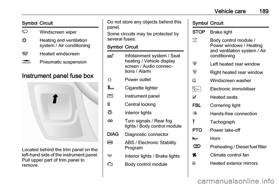
Instrument panel fuse box
Located behind the trim panel on the
left-hand side of the instrument panel. Pull upper part of trim panel to
remove.
Do not store any objects behind this
panel.
Some circuits may be protected by
several fuses.SymbolCircuitZInfotainment system / Seat
heating / Vehicle display
screen / Audio connec‐
tions / Alarm?Power outletÌCigarette lightereInstrument panelUCentral locking0Interior lightsOTurn signals / Rear fog
lights / Body control moduleDIAGDiagnostic connectoruABS / Electronic Stability
ProgramdInterior lights / Brake lightsZBody control moduleSymbolCircuitSTOPBrake lightIBody control module /
Power windows / Heating
and ventilation system / Air
conditioningmLeft heated rear windownRight heated rear windowRWindscreen washerMElectronic immobiliserUHeated seatsFBLCornering lightlHands-free connection&TachographPTOPower take-offjHornÍPreheating / Diesel fuel filterxClimate control fandHeated exterior mirrors
Page 192 of 255
190Vehicle careSymbolCircuitTLeft-hand side lightSRight-hand side lightONavigation systemADPAdditional adaptations,Power windows / Body
control module
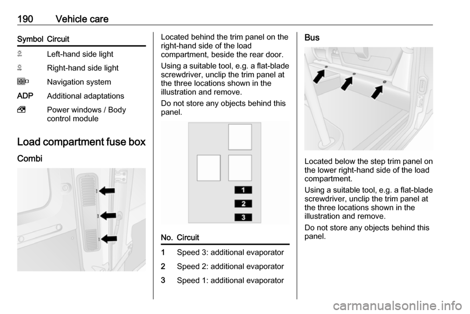
Load compartment fuse box
Combi
Located behind the trim panel on the
right-hand side of the load
compartment, beside the rear door.
Using a suitable tool, e.g. a flat-blade screwdriver, unclip the trim panel at
the three locations shown in the
illustration and remove.
Do not store any objects behind this
panel.No.Circuit1Speed 3: additional evaporator2Speed 2: additional evaporator3Speed 1: additional evaporatorBus
Located below the step trim panel on
the lower right-hand side of the load
compartment.
Using a suitable tool, e.g. a flat-blade screwdriver, unclip the trim panel at
the three locations shown in the
illustration and remove.
Do not store any objects behind this
panel.
Page 193 of 255
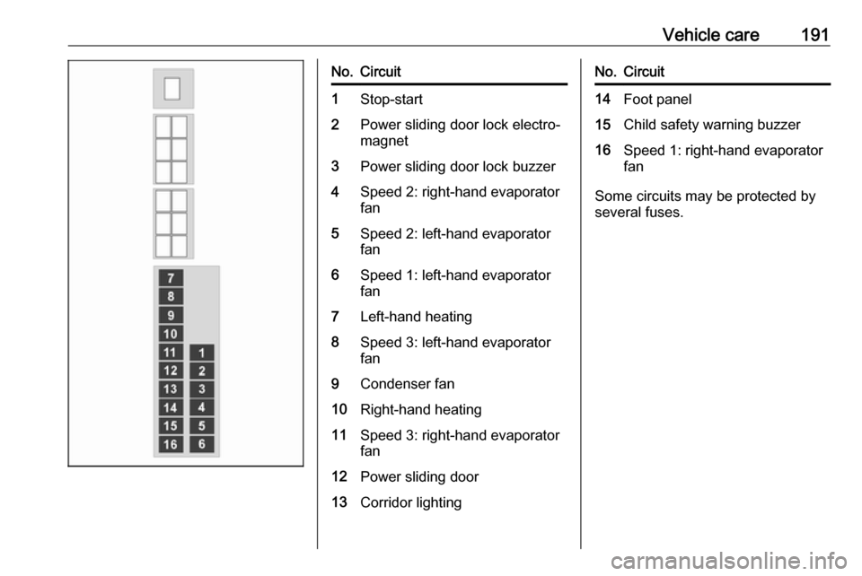
Vehicle care191No.Circuit1Stop-start2Power sliding door lock electro‐
magnet3Power sliding door lock buzzer4Speed 2: right-hand evaporator
fan5Speed 2: left-hand evaporator
fan6Speed 1: left-hand evaporator
fan7Left-hand heating8Speed 3: left-hand evaporator
fan9Condenser fan10Right-hand heating11Speed 3: right-hand evaporator
fan12Power sliding door13Corridor lightingNo.Circuit14Foot panel15Child safety warning buzzer16Speed 1: right-hand evaporator
fan
Some circuits may be protected by
several fuses.