clock OPEL MOVANO_B 2018 Manual user
[x] Cancel search | Manufacturer: OPEL, Model Year: 2018, Model line: MOVANO_B, Model: OPEL MOVANO_B 2018Pages: 265, PDF Size: 6.39 MB
Page 189 of 265
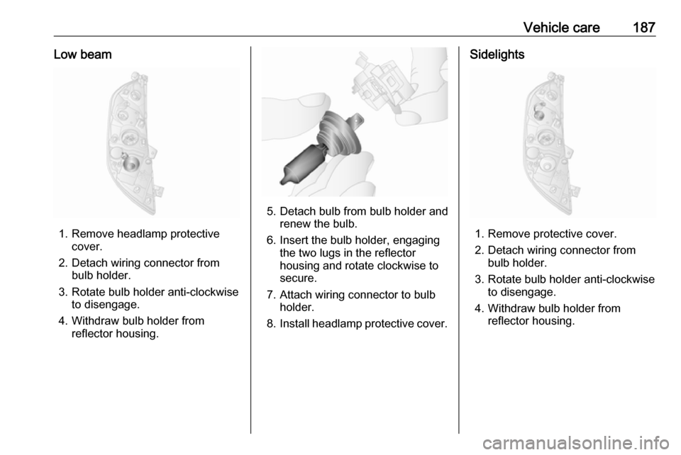
Vehicle care187Low beam
1. Remove headlamp protectivecover.
2. Detach wiring connector from bulb holder.
3. Rotate bulb holder anti-clockwise to disengage.
4. Withdraw bulb holder from reflector housing.
5. Detach bulb from bulb holder andrenew the bulb.
6. Insert the bulb holder, engaging the two lugs in the reflectorhousing and rotate clockwise to
secure.
7. Attach wiring connector to bulb holder.
8. Install headlamp protective cover.
Sidelights
1. Remove protective cover.
2. Detach wiring connector from bulb holder.
3. Rotate bulb holder anti-clockwise to disengage.
4. Withdraw bulb holder from reflector housing.
Page 190 of 265
188Vehicle care
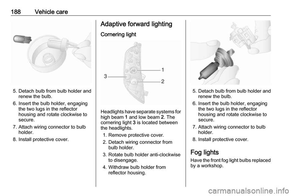
5. Detach bulb from bulb holder andrenew the bulb.
6. Insert the bulb holder, engaging the two lugs in the reflectorhousing and rotate clockwise to
secure.
7. Attach wiring connector to bulb holder.
8. Install protective cover.
Adaptive forward lighting
Cornering light
Headlights have separate systems for high beam 1 and low beam 2. The
cornering light 3 is located between
the headlights.
1. Remove protective cover.
2. Detach wiring connector from bulb holder.
3. Rotate bulb holder anti-clockwise to disengage.
4. Withdraw bulb holder from reflector housing.
5. Detach bulb from bulb holder andrenew the bulb.
6. Insert the bulb holder, engaging the two lugs in the reflectorhousing and rotate clockwise to
secure.
7. Attach wiring connector to bulb holder.
8. Install protective cover.
Fog lights
Have the front fog light bulbs replaced
by a workshop.
Page 191 of 265
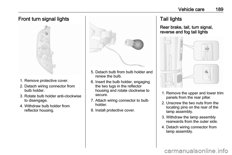
Vehicle care189Front turn signal lights
1. Remove protective cover.
2. Detach wiring connector from bulb holder.
3. Rotate bulb holder anti-clockwise to disengage.
4. Withdraw bulb holder from reflector housing.
5. Detach bulb from bulb holder andrenew the bulb.
6. Insert the bulb holder, engaging the two lugs in the reflectorhousing and rotate clockwise to
secure.
7. Attach wiring connector to bulb holder.
8. Install protective cover.
Tail lights
Rear brake, tail, turn signal,
reverse and fog tail lights
1. Remove the upper and lower trim panels from the rear pillar.
2. Unscrew the two nuts from the locating pins on the rear of the
lamp assembly.
3. Withdraw the lamp assembly rearwards from the outer side.
4. Detach wiring connector from lamp assembly.
Page 192 of 265
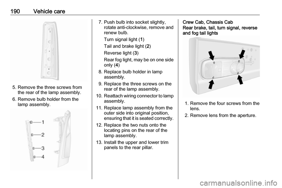
190Vehicle care
5. Remove the three screws fromthe rear of the lamp assembly.
6. Remove bulb holder from the lamp assembly.
7. Push bulb into socket slightly, rotate anti-clockwise, remove and
renew bulb.
Turn signal light ( 1)
Tail and brake light ( 2)
Reverse light ( 3)
Rear fog light, may be on one side only ( 4)
8. Replace bulb holder in lamp assembly.
9. Replace the three screws on the rear of the lamp assembly.
10. Reattach wiring connector to lamp
assembly.
11. Replace lamp assembly from the outer side into original position,
ensuring that it is seated correctly.
12. Replace the two nuts onto the locating pins on the rear of the
lamp assembly.
13. Install the upper and lower trim panels to the rear pillar.Crew Cab, Chassis CabRear brake, tail, turn signal, reverse
and fog tail lights
1. Remove the four screws from the lens.
2. Remove lens from the aperture.
Page 193 of 265
Vehicle care191
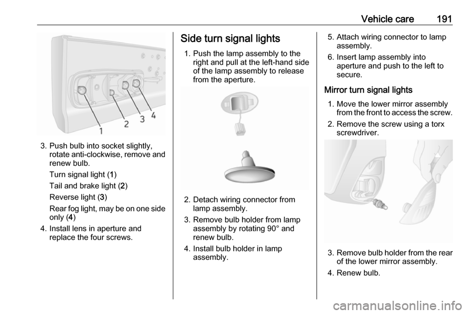
3. Push bulb into socket slightly,rotate anti-clockwise, remove and
renew bulb.
Turn signal light ( 1)
Tail and brake light ( 2)
Reverse light ( 3)
Rear fog light, may be on one side only ( 4)
4. Install lens in aperture and replace the four screws.
Side turn signal lights
1. Push the lamp assembly to the right and pull at the left-hand side
of the lamp assembly to release
from the aperture.
2. Detach wiring connector from lamp assembly.
3. Remove bulb holder from lamp assembly by rotating 90° and
renew bulb.
4. Install bulb holder in lamp assembly.
5. Attach wiring connector to lamp assembly.
6. Insert lamp assembly into aperture and push to the left to
secure.
Mirror turn signal lights 1. Move the lower mirror assembly from the front to access the screw.
2. Remove the screw using a torx screwdriver.
3. Remove bulb holder from the rear
of the lower mirror assembly.
4. Renew bulb.
Page 196 of 265
194Vehicle careFront door panel light
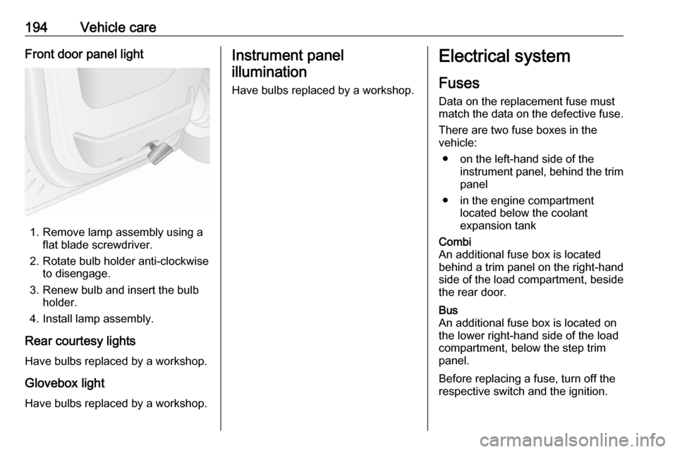
1. Remove lamp assembly using aflat blade screwdriver.
2. Rotate bulb holder anti-clockwise to disengage.
3. Renew bulb and insert the bulb holder.
4. Install lamp assembly.
Rear courtesy lights
Have bulbs replaced by a workshop.
Glovebox light
Have bulbs replaced by a workshop.
Instrument panel illumination
Have bulbs replaced by a workshop.Electrical system
Fuses Data on the replacement fuse must
match the data on the defective fuse.
There are two fuse boxes in the
vehicle:
● on the left-hand side of the instrument panel, behind the trimpanel
● in the engine compartment located below the coolant
expansion tankCombi
An additional fuse box is located
behind a trim panel on the right-hand
side of the load compartment, beside
the rear door.Bus
An additional fuse box is located on
the lower right-hand side of the load
compartment, below the step trim
panel.
Before replacing a fuse, turn off the
respective switch and the ignition.
Page 213 of 265
Vehicle care211Caution
The use of a spare wheel that issmaller than the other wheels or in combination with winter tyres
could affect driveability. Have the defective tyre replaced as soon as
possible.
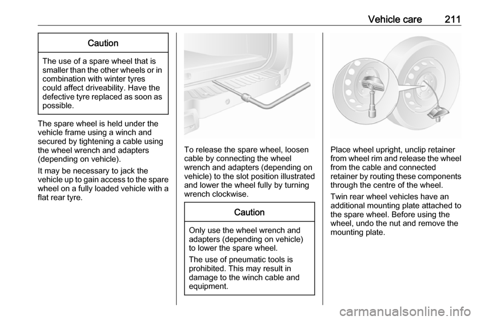
The spare wheel is held under the
vehicle frame using a winch and
secured by tightening a cable using
the wheel wrench and adapters
(depending on vehicle).
It may be necessary to jack the
vehicle up to gain access to the spare
wheel on a fully loaded vehicle with a flat rear tyre.
To release the spare wheel, loosen
cable by connecting the wheel
wrench and adapters (depending on
vehicle) to the slot position illustrated
and lower the wheel fully by turning
wrench clockwise.
Caution
Only use the wheel wrench and
adapters (depending on vehicle)
to lower the spare wheel.
The use of pneumatic tools is
prohibited. This may result in
damage to the winch cable and
equipment.
Place wheel upright, unclip retainer
from wheel rim and release the wheel
from the cable and connected
retainer by routing these components through the centre of the wheel.
Twin rear wheel vehicles have an
additional mounting plate attached to
the spare wheel. Before using the
wheel, undo the nut and remove the
mounting plate.
Page 214 of 265
212Vehicle care
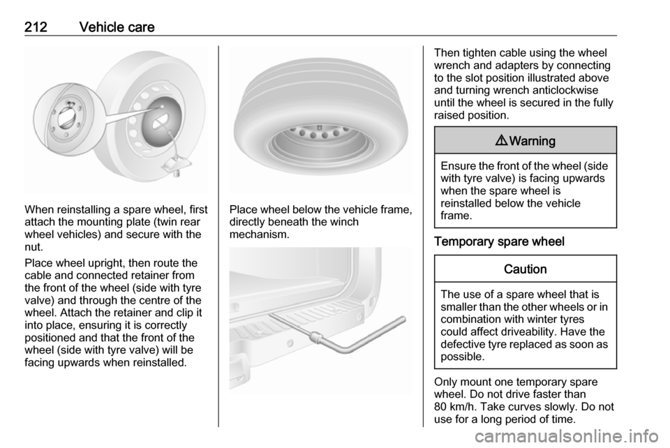
When reinstalling a spare wheel, first
attach the mounting plate (twin rear
wheel vehicles) and secure with the
nut.
Place wheel upright, then route the
cable and connected retainer from
the front of the wheel (side with tyre
valve) and through the centre of the
wheel. Attach the retainer and clip it
into place, ensuring it is correctly
positioned and that the front of the
wheel (side with tyre valve) will be
facing upwards when reinstalled.Place wheel below the vehicle frame,
directly beneath the winch
mechanism.
Then tighten cable using the wheel
wrench and adapters by connecting
to the slot position illustrated above
and turning wrench anticlockwise
until the wheel is secured in the fully
raised position.9 Warning
Ensure the front of the wheel (side
with tyre valve) is facing upwards
when the spare wheel is
reinstalled below the vehicle
frame.
Temporary spare wheel
Caution
The use of a spare wheel that is smaller than the other wheels or in combination with winter tyres
could affect driveability. Have the defective tyre replaced as soon as
possible.
Only mount one temporary spare
wheel. Do not drive faster than
80 km/h. Take curves slowly. Do not use for a long period of time.
Page 218 of 265
216Vehicle careTowingTowing the vehicle
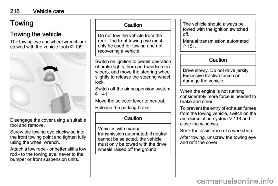
The towing eye and wheel wrench are stowed with the vehicle tools 3 199.
Disengage the cover using a suitable
tool and remove.
Screw the towing eye clockwise into
the front towing point and tighten fully using the wheel wrench.
Attach a tow rope - or better still a tow
rod - to the towing eye, never to the
bumper or front suspension units.
Caution
Do not tow the vehicle from the
rear. The front towing eye must
only be used for towing and not
recovering a vehicle.
Switch on ignition to permit operation
of brake lights, horn and windscreen
wipers, and move the steering wheel
slightly to release the steering wheel
lock.
Switch off the air suspension system 3 141.
Move the selector lever to neutral.
Release the parking brake.
Caution
Vehicles with manual
transmission automated: If neutral cannot be selected, the vehiclemust only be towed with the drive
wheels raised off the ground.
The vehicle should always be
towed with the ignition switched
off.
Manual transmission automated
3 151.Caution
Drive slowly. Do not drive jerkily.
Excessive tractive force can
damage the vehicle.
When the engine is not running,
considerably more force is needed to
brake and steer.
To prevent the entry of exhaust fumes
from the towing vehicle, switch on the air recirculation system 3 118 and
close the windows.
Seek the assistance of a workshop.
After towing, unscrew the towing eye
and refit the cover.
Page 259 of 265

257Charging system .......................... 98
Child locks ................................... 28
Child restraint installation locations ................................... 66
Child restraints.............................. 63
Child restraint systems ................63
Cigarette lighter ........................... 90
Cleaning the vehicle ...................217
Climate control ............................. 16
Climate control systems .............117
Clock ............................................ 88
Coat hooks ................................... 74
Collision damage repair ..............253
Control indicators.......................... 94
Control of the vehicle .................134
Controls ........................................ 85
Convex shape .............................. 36
Coolant ....................................... 179
Coolant and antifreeze ...............223
Coolant heater ............................ 124
Cornering light ....................112, 188
Coupling ball bar ........................173
Cruise control ....................102, 160
Cupholders .................................. 74
D Danger, Warnings and Cautions ...4
Dashboard .................................... 10
Daytime running lights ...............111
Declaration of conformity ............249DEF............................................ 144
Demisting and defrosting ..............16
Diesel exhaust fluid ....................144
Diesel fuel ................................... 169
Diesel fuel filter .......................... 184
Diesel fuel system bleeding .......184
Diesel particle filter ....................143
Door locks..................................... 23
Door open .................................. 102
Doors ............................................ 28
DPF (diesel particle filter) ...........143
Drink holders ................................ 74
Driver assistance systems ..........160
Driver Information Centre ...........103
Driving characteristics and towing tips .............................. 172
Driving economically................... 134
Driving hints ................................ 134
E ECO mode .................................. 134
ecoScoring.................................. 105
Electric adjustment ......................36
Electrical accessories ...................88
Electrical system......................... 194
Electronic climate control system 119
Electronic driving programmes ..153
Electronic Stability Program .....
................................ 100, 158, 173
Electronic Stability Program off . 100Emergency exit .......................39, 41
End-of-life vehicle recovery .......177
Engine compartment fuse box ...196
Engine coolant ........................... 179
Engine coolant temperature ......100
Engine coolant temperature gauge ....................................... 92
Engine data ............................... 228
Engine Drag Torque Control ......158
Engine exhaust .......................... 143
Engine identification ...................226
Engine oil ...........178, 223, 227, 246
Engine oil additives ....................223
Engine oil level monitor ................93
Engine oil pressure ....................101
Engine oil viscosity grades .........223
Enhanced Traction function....... ................................ 157, 158, 160
Event data recorders ..................253
Exhaust gases ............................ 143
Exit lighting ................................ 116
Exterior care .............................. 217
Exterior light ............................... 102
Exterior lighting ....................14, 109
Exterior mirrors ............................. 36
F
Fault ........................................... 154
Fire extinguisher ........................... 81
First aid ......................................... 81