charging OPEL MOVANO_B 2018 Owner's Manual
[x] Cancel search | Manufacturer: OPEL, Model Year: 2018, Model line: MOVANO_B, Model: OPEL MOVANO_B 2018Pages: 265, PDF Size: 6.39 MB
Page 86 of 265

84Instruments and controlsInstruments and
controlsControls ....................................... 85
Steering wheel adjustment ........85
Steering wheel controls .............85
Horn ........................................... 85
Steering column controls ...........85
Windscreen wiper/washer .........86
Outside temperature ..................87
Clock ......................................... 88
Power outlets ............................. 88
Cigarette lighter ......................... 90
Ashtrays .................................... 90
Warning lights, gauges and indi‐ cators ........................................... 90
Instrument cluster ......................90
Speedometer ............................. 90
Odometer .................................. 91
Trip odometer ............................ 91
Tachometer ............................... 91
Fuel gauge ................................ 92
AdBlue gauge ............................ 92
Engine coolant temperature gauge ....................................... 92
Engine oil level monitor .............93
Service display .......................... 93Transmission display .................94
Control indicators ......................94
Turn signal ................................. 97
Seat belt reminder .....................97
Airbag and belt tensioners .........97
Airbag deactivation ....................97
Charging system .......................98
Malfunction indicator light ..........98
Service vehicle soon .................98
Stop engine ............................... 99
Brake system ............................. 99
Antilock brake system (ABS) .....99
Upshift ....................................... 99
Lane departure warning ............99
Electronic Stability Program ....100
Electronic Stability Program off ........................................... 100
Engine coolant temperature ....100
Preheating ............................... 100
AdBlue ..................................... 100
Tyre pressure monitoring system .................................... 100
Engine oil pressure ..................101
Low fuel ................................... 101
Stop-start system ....................101
Exterior light ............................ 102
High beam ............................... 102
High beam assist .....................102
Fog light ................................... 102
Rear fog light ........................... 102Cruise control.......................... 102
Tachograph ............................. 102
Door open ................................ 102
Information displays ...................103
Driver Information Centre ........103
Info display .............................. 103
Vehicle messages ......................104
Warning chimes .......................104
Trip computer ............................. 105
Tachograph ................................ 107
Page 91 of 265
Instruments and controls89
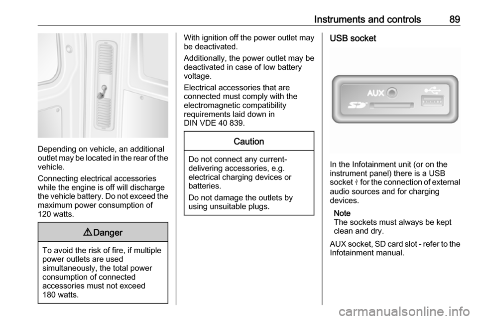
Depending on vehicle, an additional
outlet may be located in the rear of the
vehicle.
Connecting electrical accessories
while the engine is off will discharge
the vehicle battery. Do not exceed the
maximum power consumption of
120 watts.
9 Danger
To avoid the risk of fire, if multiple
power outlets are used
simultaneously, the total power
consumption of connected
accessories must not exceed
180 watts.
With ignition off the power outlet may
be deactivated.
Additionally, the power outlet may be
deactivated in case of low battery
voltage.
Electrical accessories that are
connected must comply with the
electromagnetic compatibility
requirements laid down in
DIN VDE 40 839.Caution
Do not connect any current- delivering accessories, e.g.
electrical charging devices or
batteries.
Do not damage the outlets by
using unsuitable plugs.
USB socket
In the Infotainment unit (or on the
instrument panel) there is a USB
socket M for the connection of external
audio sources and for charging
devices.
Note
The sockets must always be kept
clean and dry.
AUX socket, SD card slot - refer to the
Infotainment manual.
Page 98 of 265
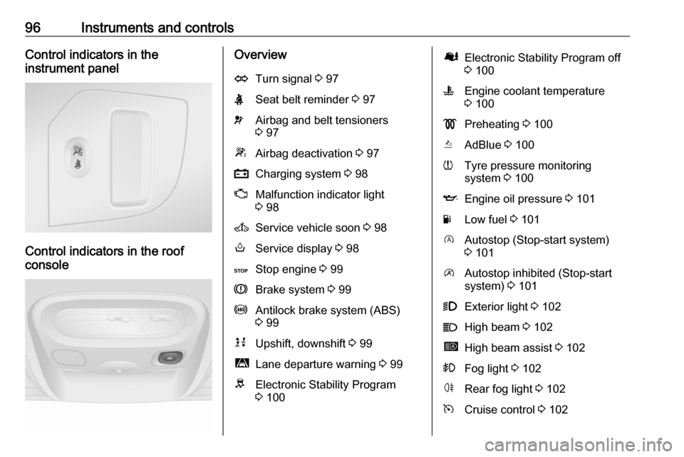
96Instruments and controlsControl indicators in the
instrument panel
Control indicators in the roof
console
OverviewOTurn signal 3 97XSeat belt reminder 3 97vAirbag and belt tensioners
3 97WAirbag deactivation 3 97pCharging system 3 98ZMalfunction indicator light
3 98AService vehicle soon 3 98oService display 3 98CStop engine 3 99RBrake system 3 99uAntilock brake system (ABS)
3 99kjUpshift, downshift 3 99ìLane departure warning 3 99RElectronic Stability Program
3 100ØElectronic Stability Program off
3 100WEngine coolant temperature
3 100!Preheating 3 100YAdBlue 3 100wTyre pressure monitoring
system 3 100IEngine oil pressure 3 101YLow fuel 3 101DAutostop (Stop-start system)
3 101\Autostop inhibited (Stop-start
system) 3 1019Exterior light 3 102CHigh beam 3 102íHigh beam assist 3 102>Fog light 3 102øRear fog light 3 102mCruise control 3 102
Page 100 of 265
98Instruments and controls9Danger
Risk of fatal injury for a child using
a child restraint system together
with activated front passenger
airbag.
Risk of fatal injury for an adult
person with deactivated front
passenger airbag.
Airbag system 3 57, belt tensioners
3 53, airbag deactivation 3 61.
Charging system p illuminates red.
Illuminates when the ignition is
switched on and extinguishes shortly after the engine starts.
Illuminates when the engine is
running
Stop, switch off engine. Vehicle
battery is not charging. Engine
cooling may be interrupted. The
brake servo unit may cease to be
effective. Seek the assistance of a
workshop.
Malfunction indicator light
Z illuminates or flashes yellow.
Illuminates briefly when the ignition is
switched on.
Illuminates when the engine is
running
Fault in the emission control system. The permitted emission limits may be exceeded. Seek the assistance of a
workshop immediately.
If Z illuminates in combination with
A , stop vehicle and switch off engine
as soon as possible.9 Warning
Have the cause of the fault
remedied immediately by a
workshop.
Flashes when the engine is
running
Fault that could lead to catalytic
converter damage. Ease up on the
accelerator until the flashing stops.
Seek the immediate assistance of a
workshop.
Service vehicle soon
A illuminates yellow.
Illuminates briefly when the ignition is
switched on.
The vehicle needs a service.
May illuminate in combination with
another control indicator or a
message in the Driver Information
Centre 3 103.
Illuminates if cleaning of the diesel particle filter is required and
automatic cleaning does not occur
3 143.9 Warning
Have the cause of the fault
remedied immediately by a
workshop.
Service display
Control indicator o also illuminates in
the Driver Information Centre when
the remaining distance before the
next service reaches 0 km or the
service date is due.
Page 137 of 265
Driving and operating135Caution
Vehicles equipped with hydraulic
power steering:
If the steering wheel is turned until it reaches the end of its travel, and
is held in that position for more
than 15 seconds, damage may
occur to the power steering
system and there may be loss of
power steering assist.
Starting and operating
New vehicle running-in
Do not brake unnecessarily hard for
the first few journeys and after new
disc brake pads have been fitted.
During the first drive, smoke may
occur because of wax and oil
evaporating off the exhaust system.
Park the vehicle in the open for a
while after the first drive and avoid
inhaling the fumes.
During the running-in period fuel and engine oil consumption may be
higher and the cleaning process of the diesel particle filter may take
place more often. Autostop may be
inhibited to allow for charging the
vehicle battery.
Stop-start system 3 137.
Diesel particle filter 3 143.
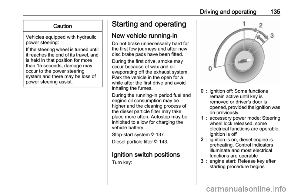
Ignition switch positions Turn key:0:ignition off: Some functions
remain active until key is
removed or driver's door is
opened, provided the ignition was
on previously1:accessory power mode: Steering wheel lock released, some
electrical functions are operable,
ignition is off2:ignition is on, diesel engine is
preheating. Control indicators
illuminate and most electrical
functions are operable3:engine start: Release key after
starting procedure begins
Page 184 of 265
182Vehicle care
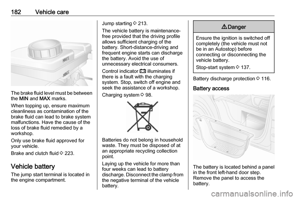
The brake fluid level must be betweenthe MIN and MAX marks.
When topping up, ensure maximum cleanliness as contamination of the
brake fluid can lead to brake system
malfunctions. Have the cause of the
loss of brake fluid remedied by a
workshop.
Only use brake fluid approved for your vehicle.
Brake and clutch fluid 3 223.
Vehicle battery
The jump start terminal is located in
the engine compartment.
Jump starting 3 213.
The vehicle battery is maintenance-
free provided that the driving profile
allows sufficient charging of the
battery. Short-distance-driving and
frequent engine starts can discharge
the battery. Avoid the use of
unnecessary electrical consumers.
Control indicator p illuminates if
there is a fault with the charging
system. Stop, switch off engine and
seek the assistance of a workshop.
Charging system 3 98.
Batteries do not belong in household
waste. They must be disposed of at
an appropriate recycling collection
point.
Laying up the vehicle for more than
four weeks can lead to battery
discharge. Disconnect the clamp from the negative terminal of the vehicle
battery.
9 Danger
Ensure the ignition is switched off
completely (the vehicle must not
be in an Autostop) before
connecting or disconnecting the
vehicle battery.
Stop-start system 3 137.
Battery discharge protection 3 116.
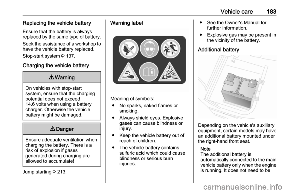
Battery access
The battery is located behind a panel in the front left-hand door step.
Remove the panel to access the
battery.
Page 185 of 265
Vehicle care183Replacing the vehicle batteryEnsure that the battery is always
replaced by the same type of battery.
Seek the assistance of a workshop to
have the vehicle battery replaced.
Stop-start system 3 137.
Charging the vehicle battery9 Warning
On vehicles with stop-start
system, ensure that the charging potential does not exceed
14.6 volts when using a battery
charger. Otherwise the vehicle
battery might be damaged.
9 Danger
Ensure adequate ventilation when
charging the battery. There is a
risk of explosion if gases
generated during charging are
allowed to accumulate!
Jump starting 3 213.
Warning label
Meaning of symbols:
● No sparks, naked flames or smoking.
● Always shield eyes. Explosive gases can cause blindness or
injury.
● Keep the vehicle battery out of reach of children.
● The vehicle battery contains sulfuric acid which could cause
blindness or serious burn
injuries.
● See the Owner's Manual for further information.
● Explosive gas may be present in the vicinity of the battery.
Additional battery
Depending on the vehicle's auxiliary
equipment, certain models may have
an additional battery mounted under
the right-hand front seat.
Note
The additional battery is
automatically connected to the main vehicle battery only when the engine
is running. It does not need to be
Page 186 of 265
184Vehicle caremanually disconnected before
disconnecting the main vehicle
battery or before jump starting the vehicle.
The terminals are designed for
additional electrical consumers up to a maximum of 50 A.
Jump starting 3 213.
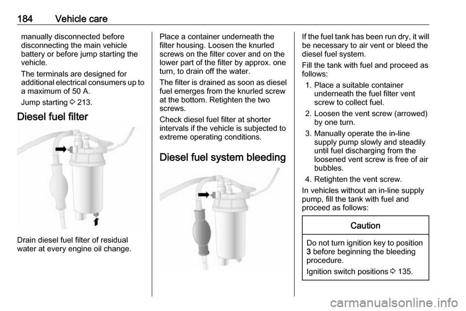
Diesel fuel filter
Drain diesel fuel filter of residual
water at every engine oil change.
Place a container underneath the
filter housing. Loosen the knurled
screws on the filter cover and on the
lower part of the filter by approx. one
turn, to drain off the water.
The filter is drained as soon as diesel fuel emerges from the knurled screw
at the bottom. Retighten the two
screws.
Check diesel fuel filter at shorter
intervals if the vehicle is subjected to
extreme operating conditions.
Diesel fuel system bleedingIf the fuel tank has been run dry, it will be necessary to air vent or bleed the
diesel fuel system.
Fill the tank with fuel and proceed as
follows:
1. Place a suitable container underneath the fuel filter vent
screw to collect fuel.
2. Loosen the vent screw (arrowed) by one turn.
3. Manually operate the in-line supply pump slowly and steadily
until fuel discharging from the
loosened vent screw is free of air
bubbles.
4. Retighten the vent screw.
In vehicles without an in-line supply
pump, fill the tank with fuel and
proceed as follows:Caution
Do not turn ignition key to position
3 before beginning the bleeding
procedure.
Ignition switch positions 3 135.
Page 209 of 265
![OPEL MOVANO_B 2018 Owners Manual Vehicle care207power outlet or cigarette lighter
socket.
For this type, the red < and
black ] power supply leads will not
be present.
To avoid discharging the battery,we recommend running the
engine OPEL MOVANO_B 2018 Owners Manual Vehicle care207power outlet or cigarette lighter
socket.
For this type, the red < and
black ] power supply leads will not
be present.
To avoid discharging the battery,we recommend running the
engine](/img/37/18908/w960_18908-208.png)
Vehicle care207power outlet or cigarette lighter
socket.
For this type, the red < and
black ] power supply leads will not
be present.
To avoid discharging the battery,we recommend running the
engine.
11. Set the rocker switch on the compressor to position I. The tyre
is filled with sealant.
12. The compressor pressure gauge briefly indicates up to six bar.
Then the pressure starts to drop.
13. All of the sealant is pumped into the tyre. Then the tyre is inflated.
14. The prescribed tyre pressureshould be obtained within
ten minutes. Tyre pressure
3 247 . When the correct pressure
is obtained, turn off the
compressor by setting rocker
switch to position O.
If the prescribed tyre pressure is
not obtained within ten minutes,
remove the tyre repair kit. Move
the vehicle one tyre rotation
(approx. two metres). Reattach
the tyre repair kit and continue the
filling procedure for ten minutes. If the prescribed tyre pressure is still
not obtained, the tyre is too badly
damaged. Seek the assistance of
a workshop.
Drain excess tyre pressure with
the button beside the pressure
indicator.
Do not run the compressor for
longer than ten minutes.
15. Detach the tyre repair kit.
16. Remove any excess sealant using a cloth.
17. Take the label indicating maximum permitted speed from
the tyre repair kit and affix in the
driver's field of view.
18. Screw the sealant filler hose to the
free connection on the sealant
bottle. This prevents sealant from
escaping. Store the sealant bottle in the plastic bag. Stow tyre repair
kit under the front seat.
Page 259 of 265

257Charging system .......................... 98
Child locks ................................... 28
Child restraint installation locations ................................... 66
Child restraints.............................. 63
Child restraint systems ................63
Cigarette lighter ........................... 90
Cleaning the vehicle ...................217
Climate control ............................. 16
Climate control systems .............117
Clock ............................................ 88
Coat hooks ................................... 74
Collision damage repair ..............253
Control indicators.......................... 94
Control of the vehicle .................134
Controls ........................................ 85
Convex shape .............................. 36
Coolant ....................................... 179
Coolant and antifreeze ...............223
Coolant heater ............................ 124
Cornering light ....................112, 188
Coupling ball bar ........................173
Cruise control ....................102, 160
Cupholders .................................. 74
D Danger, Warnings and Cautions ...4
Dashboard .................................... 10
Daytime running lights ...............111
Declaration of conformity ............249DEF............................................ 144
Demisting and defrosting ..............16
Diesel exhaust fluid ....................144
Diesel fuel ................................... 169
Diesel fuel filter .......................... 184
Diesel fuel system bleeding .......184
Diesel particle filter ....................143
Door locks..................................... 23
Door open .................................. 102
Doors ............................................ 28
DPF (diesel particle filter) ...........143
Drink holders ................................ 74
Driver assistance systems ..........160
Driver Information Centre ...........103
Driving characteristics and towing tips .............................. 172
Driving economically................... 134
Driving hints ................................ 134
E ECO mode .................................. 134
ecoScoring.................................. 105
Electric adjustment ......................36
Electrical accessories ...................88
Electrical system......................... 194
Electronic climate control system 119
Electronic driving programmes ..153
Electronic Stability Program .....
................................ 100, 158, 173
Electronic Stability Program off . 100Emergency exit .......................39, 41
End-of-life vehicle recovery .......177
Engine compartment fuse box ...196
Engine coolant ........................... 179
Engine coolant temperature ......100
Engine coolant temperature gauge ....................................... 92
Engine data ............................... 228
Engine Drag Torque Control ......158
Engine exhaust .......................... 143
Engine identification ...................226
Engine oil ...........178, 223, 227, 246
Engine oil additives ....................223
Engine oil level monitor ................93
Engine oil pressure ....................101
Engine oil viscosity grades .........223
Enhanced Traction function....... ................................ 157, 158, 160
Event data recorders ..................253
Exhaust gases ............................ 143
Exit lighting ................................ 116
Exterior care .............................. 217
Exterior light ............................... 102
Exterior lighting ....................14, 109
Exterior mirrors ............................. 36
F
Fault ........................................... 154
Fire extinguisher ........................... 81
First aid ......................................... 81