brakes OPEL MOVANO_B 2019 Owner's Manual
[x] Cancel search | Manufacturer: OPEL, Model Year: 2019, Model line: MOVANO_B, Model: OPEL MOVANO_B 2019Pages: 251, PDF Size: 6.46 MB
Page 21 of 251
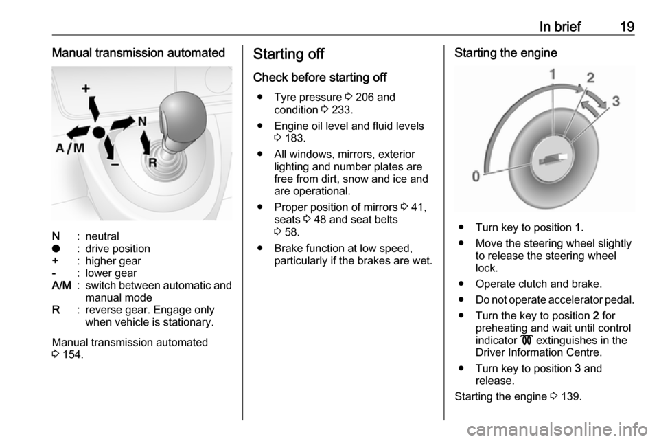
In brief19Manual transmission automatedN:neutralo:drive position+:higher gear-:lower gearA/M:switch between automatic and
manual modeR:reverse gear. Engage only
when vehicle is stationary.
Manual transmission automated
3 154.
Starting off
Check before starting off ● Tyre pressure 3 206 and
condition 3 233.
● Engine oil level and fluid levels 3 183.
● All windows, mirrors, exterior lighting and number plates are
free from dirt, snow and ice and
are operational.
● Proper position of mirrors 3 41,
seats 3 48 and seat belts
3 58.
● Brake function at low speed, particularly if the brakes are wet.Starting the engine
● Turn key to position 1.
● Move the steering wheel slightly to release the steering wheel
lock.
● Operate clutch and brake.
● Do not operate accelerator pedal.
● Turn the key to position 2 for
preheating and wait until control
indicator ! extinguishes in the
Driver Information Centre.
● Turn key to position 3 and
release.
Starting the engine 3 139.
Page 138 of 251

136Driving and operatingDriving and
operatingDriving hints ............................... 137
Driving economically ...............137
Control of the vehicle ...............137
Steering ................................... 137
Starting and operating ...............138
New vehicle running-in ............138
Ignition switch positions ...........138
Starting the engine ..................139
Idle speed control ....................140
Overrun cut-off ........................ 140
Stop-start system ....................140
Parking .................................... 143
Air suspension ......................... 144
Engine exhaust .......................... 146
Diesel particle filter ..................146
Catalytic converter ...................146
AdBlue ..................................... 147
Manual transmission ..................154
Manual transmission automa‐ ted .............................................. 154
Transmission display ...............154
Starting the engine ..................155
Selector lever .......................... 155Manual mode........................... 156
Electronic driving programmes 156
Fault ........................................ 157
Interruption of power supply ....158
Brakes ........................................ 158
Antilock brake system .............158
Parking brake .......................... 159
Brake assist ............................. 160
Hill start assist ......................... 160
Ride control systems .................160
Traction Control system ..........160
Electronic Stability Control ......161
Limited-slip rear axle ...............163
Driver assistance systems .........163
Cruise control .......................... 163
Speed limiter ........................... 165
Active emergency braking .......167
Parking assist .......................... 169
Rear view camera ...................171
Lane departure warning ..........173
Fuel ............................................ 174
Fuel for diesel engines ............174
Refuelling ................................ 175
Trailer hitch ................................ 177
General information .................177
Driving characteristics and towing tips .............................. 177
Trailer towing ........................... 177Towing equipment ...................178
Trailer stability assist ...............178
Auxiliary features .......................178
Power take-off ......................... 178
Page 160 of 251

158Driving and operatingInterruption of power supplyThe clutch is not disengaged if there
is an interruption of the power supply
when a gear is engaged. The vehicle
cannot move.
If the vehicle battery is discharged,
start the vehicle using jump leads
3 218.
If the cause of the fault is not a
discharged vehicle battery, seek the
assistance of a workshop.
If neutral cannot be selected, the
vehicle must only be towed with the
drive wheels raised off the ground
3 221.
Towing the vehicle 3 221.Brakes
The brake system comprises two
independent brake circuits.
If a brake circuit fails, the vehicle can
still be braked using the other brake
circuit. However, braking effect is
achieved only when you depress the
brake pedal firmly. You need to use
considerably more force for this. The
braking distance is extended. Seek
the assistance of a workshop before
continuing your journey.
When the engine is not running, the
support of the brake servo unit
disappears once the brake pedal has
been depressed once or twice.
Braking effect is not reduced, but
braking requires significantly greater
force. It is especially important to bear this in mind when being towed.
Control indicator R 3 102.
Antilock brake system
Antilock brake system (ABS)
prevents the wheels from locking.ABS starts to regulate brake pressure as soon as a wheel shows a tendency to lock. The vehicle remains
steerable, even during hard braking.
ABS control is made apparent
through a pulse in the brake pedal
and the noise of the regulation
process.
For optimum braking, keep the brake
pedal fully depressed throughout the
braking process, despite the fact that
the pedal is pulsating. Do not reduce
the pressure on the pedal.
Control indicator u 3 102.
Fault
If control indicators u and j
illuminate with the messages CHECK
ABS and CHECK ESP in the Driver
Information Centre, there is a fault in
the ABS. The brake system remains
operational but without ABS
regulation.
Page 162 of 251
160Driving and operatingBrake assistIf the brake pedal is depressed
quickly and forcefully, maximum
brake force is automatically applied
(full braking).
Maintain steady pressure on the
brake pedal for as long as full braking
is required. Maximum brake force is
automatically reduced when the
brake pedal is released.
Brake assist is not available during an
Autostop.
Stop-start system 3 140.
Hill start assist
The system helps prevent unintended movement when driving away on
inclines.
When releasing the brake pedal after
stopping on an incline (with the
selector lever in a forward gear or
reverse gear), the brakes remain on
for a further 2 seconds. The brakes
release automatically as soon as the
vehicle begins to accelerate.Caution
The Hill start assist cannot
completely prevent vehicle
movement in all situations
(extremely steep gradients, etc.).
If necessary, depress the brake
pedal to prevent the vehicle from
rolling backwards.
The Hill start assist is not active
during an Autostop.
Stop-start system 3 140.
Ride control systems
Traction Control system The Traction Control system (TC) is a component part of the Electronic
Stability Control (ESC) which
improves driving stability when
necessary, regardless of the type of
road surface or tyre grip, by
preventing the drive wheels from
spinning.
As soon as the drive wheels start to spin, engine output is reduced and
the wheel spinning the most is braked
individually. This considerably
improves the driving stability of the
vehicle on slippery road surfaces.
TC is operational as soon as the
ignition is switched on and control
indicator b extinguishes in the
instrument cluster. A corresponding
message also appears in the Driver
Information Centre 3 106.
When TC is active b flashes.
Page 169 of 251
Driving and operating167Switching off the system
Press U.
Yellow control indicator U
extinguishes in the instrument cluster.
Maximum speed limiterIn accordance with local or national
regulations, the vehicle may be
equipped with a fixed maximum
speed limiter that cannot be disabled.
If equipped, a warning label indicating the fixed maximum speed limit (90 to
130 km/h) is located on the
instrument panel.
Deviations from the maximum speed
limit may occur briefly when driving
downhill, for physical reasons.
A warning chime may sound for
10 seconds if the vehicle briefly
exceeds the set limit.
Vehicles also equipped with speed
limiter: the maximum speed cannot
be exceeded by depressing the
accelerator pedal firmly beyond the
point of resistance.Active emergency braking
Active emergency braking can help to reduce the damage and injury from
crashes with vehicles directly ahead,
when a collision can no longer be
avoided either by manual braking or
by steering. The feature uses various
inputs (e.g. camera sensor, radar
sensor, brake pressure, vehicle
speed) to calculate the probability of a frontal collision.9 Warning
This system is not intended to
replace the driver responsibility for driving the vehicle and looking
ahead. Its function is limited to
supplemental use only to reduce
the vehicle speed before a
collision.
The system only detects vehicles
driving in the same direction of
traffic.
After a sudden lane change, the
system needs a certain time to
detect the next preceding vehicle.
The driver must always be ready
to take action and apply the brakes and steer to avoid collisions.
Operation conditions
The system is operational at a vehicle
speed between 15 km/h and
100 km/h.
Activation The system is automatically activewhen the ignition is switched on.
Functionality
When driving in the speed range
mentioned above and a risk of
collision with the vehicle ahead is
imminent, l will flash and a warning
chime sounds.
The indicator light l and the chimes
stop when the system detects that a
collision is not imminent anymore.
Just before the imminent collision, the system brakes automatically to
reduce the impact speed of the
collision or prohibit a crash.
Page 171 of 251
Driving and operating169●detecting a vehicle when weather
limits visibility, such as in fog,
rain, or snow
● driving during nighttime
● sensor in the windscreen or radar
unit behind the front bumper
blocked by snow, ice, slush, mud, dirt, etc.
● windscreen damaged or affected
by foreign objects, e.g. stickers
Complete attention is always required
while driving, and you should be
ready to take action and apply the
brakes and / or steer the vehicle to
avoid crashes.
Fault
In case the system requires a service,
a message is displayed in the Driver
Information Centre.
Additionally, warning lights l and
j illuminate at the same time.
When the system detects that its
function is not available, warning light l or j illuminates and stays on.
Additionally, a message in the Driver
Information Centre appears. The
system may be temporarily disrupted(for example: radar or camera
obscured by dirt, mud, snow etc.). In
this case, park the vehicle and switch
off the engine. Clean the windscreen
area around the camera and the
detection zone of the radar in the front bumper. When the warning lights and
messages still appear after starting
the vehicle again, seek the
assistance of a workshop.
Parking assist9 Warning
It is the driver who bears full
responsibility for the parking
manoeuvre.
Always check the surrounding
area while reversing and using the rear parking assist system.
The parking assist measures the
distance between the vehicle and
obstacles behind the vehicle. It
informs and warns the driver by giving acoustic signals.
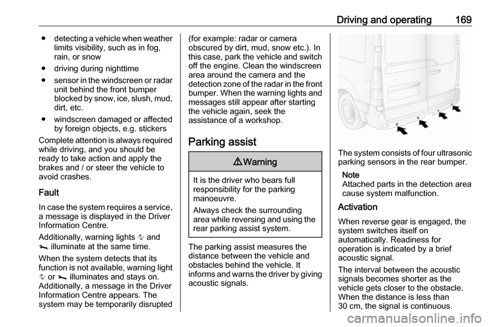
The system consists of four ultrasonic parking sensors in the rear bumper.
Note
Attached parts in the detection area
cause system malfunction.
Activation
When reverse gear is engaged, the
system switches itself on
automatically. Readiness for
operation is indicated by a brief
acoustic signal.
The interval between the acoustic
signals becomes shorter as the
vehicle gets closer to the obstacle.
When the distance is less than
30 cm, the signal is continuous.
Page 179 of 251

Driving and operating177Trailer hitch
General information
Only use towing equipment that has
been approved for your vehicle.
Entrust fitting of towing equipment at
a later date to a workshop. It may be
necessary to make changes that
affect the cooling system, heat
shields or other equipment.
Driving characteristics and towing tips
In the case of trailers with brakes,
attach the breakaway stopping cable.
Before attaching a trailer, lubricate
the coupling ball. However, do not do
so if a stabiliser, which acts on the coupling ball, is being used to reduce
snaking movements. For trailers with
low driving stability the use of a
stabiliser is recommended.
A maximum speed of 80 km/h must
not be exceeded, even in countries
where higher speeds are permitted.If the trailer starts snaking, drive more slowly, do not attempt to correct the
steering and brake sharply if
necessary.
When driving downhill, drive in the
same gear as if driving uphill and
drive at a similar speed.
Adjust tyre pressure to the value
specified for full load 3 233.
Trailer towing
Trailer loads The permissible trailer loads are
vehicle-dependent and engine-
dependent maximum values which
must not be exceeded. The actual
trailer load is the difference between
the actual gross weight of the trailer
and the actual coupling socket load
with the trailer coupled.
The permissible trailer loads are
specified in the vehicle documents. In
general, they are valid for gradients
up to max. 12%.
The permitted trailer load applies up to the specified incline and up to an
altitude of 1000 m above sea level.Since engine power decreases as
altitude increases due to the air
becoming thinner, therefore reducing
climbing ability, the permissible gross
train weight also decreases by 10%
for every 1000 m of additional
altitude. The gross train weight does
not have to be reduced when driving
on roads with slight inclines (less than 8%, e.g. motorways).
The permissible gross train weight
must not be exceeded. This weight is
specified on the identification plate
3 231.
Vertical coupling load
The vertical coupling load is the load
exerted by the trailer on the coupling
ball. It can be varied by changing the
weight distribution when loading the
trailer.
The maximum permissible vertical
coupling load is specified on the
towing equipment identification plate
and in the vehicle documents. Always aim for the maximum load, especially in the case of heavy trailers. The
vertical coupling load should never
fall below 25 kg.
Page 182 of 251

180Vehicle careVehicle careGeneral Information...................181
Accessories and vehicle modifications .......................... 181
Vehicle storage ........................181
End-of-life vehicle recovery .....182
Vehicle checks ........................... 182
Performing work ......................182
Bonnet ..................................... 182
Engine oil ................................. 183
Engine coolant ......................... 185
Power steering fluid .................185
Washer fluid ............................ 186
Brakes ..................................... 187
Brake fluid ............................... 187
Vehicle battery ......................... 187
Diesel fuel filter ........................189
Diesel fuel system bleeding .....189
Wiper blade replacement ........190
Bulb replacement .......................191
Headlights ............................... 191
Front fog lights ......................... 194
Front turn lights .......................194
Tail lights ................................. 195
Side turn lights ......................... 196Centre high-mounted brake
light ......................................... 197
Number plate light ...................198
Interior lights ............................ 198
Instrument panel illumination ...199
Electrical system ........................200
Fuses ....................................... 200
Engine compartment fuse box . 201
Instrument panel fuse box .......201
Load compartment fuse box ....202
Vehicle tools .............................. 204
Tools ........................................ 204
Wheels and tyres .......................205
Tyres ....................................... 205
Winter tyres ............................. 206
Tyre designations ....................206
Tyre pressure .......................... 206
Tyre pressure monitoring system .................................... 207
Tread depth ............................. 209
Changing tyre and wheel size . 210 Wheel covers ........................... 210
Tyre chains .............................. 210
Tyre repair kit .......................... 211
Wheel changing .......................214
Spare wheel ............................ 216
Jump starting ............................. 218Towing....................................... 221
Towing the vehicle ...................221
Towing another vehicle ...........222
Appearance care .......................222
Exterior care ............................ 222
Interior care ............................. 224
Page 189 of 251
Vehicle care187BrakesIn the event of minimum thickness ofthe brake lining, a squealing noise
sounds during braking.
Continued driving is possible but
have the brake linings replaced as
soon as possible.
Once new brake linings are installed,
do not brake unnecessarily hard for
the first few journeys.
Brake fluid9 Warning
Brake fluid is poisonous and
corrosive. Avoid contact with eyes, skin, fabrics and painted surfaces.
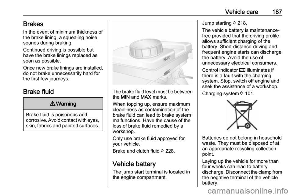
The brake fluid level must be betweenthe MIN and MAX marks.
When topping up, ensure maximum cleanliness as contamination of the
brake fluid can lead to brake system
malfunctions. Have the cause of the
loss of brake fluid remedied by a
workshop.
Only use brake fluid approved for
your vehicle.
Brake and clutch fluid 3 228.
Vehicle battery
The jump start terminal is located in
the engine compartment.
Jump starting 3 218.
The vehicle battery is maintenance-
free provided that the driving profile
allows sufficient charging of the
battery. Short-distance-driving and
frequent engine starts can discharge
the battery. Avoid the use of
unnecessary electrical consumers.
Control indicator p illuminates if
there is a fault with the charging
system. Stop, switch off engine and
seek the assistance of a workshop.
Charging system 3 101.
Batteries do not belong in household
waste. They must be disposed of at
an appropriate recycling collection
point.
Laying up the vehicle for more than
four weeks can lead to battery
discharge. Disconnect the clamp from the negative terminal of the vehicle
battery.
Page 241 of 251

Customer information239Operating data in the vehicleControl units process data for
operation of the vehicle.
This data includes, e.g.: ● vehicle status information (e.g. speed, movement delay, lateral
acceleration, wheel rotation rate,
"seat belts fastened" display)
● ambient conditions (e.g. temperature, rain sensor,
distance sensor)
As a rule such data is transient, not
stored for longer than an operational
cycle, and only processed on board
the vehicle itself. Control units often
include data storage (including the
vehicle key). This is used to allow
information to be documented
temporarily or permanently on vehicle
condition, component stress,
maintenance requirements and
technical events and errors.Depending on technical equipment
level, the data stored is as follows:
● system component operating states (e.g. fill level, tyre
pressure, battery status)
● faults and defects in important system components (e.g. lights,brakes)
● system reactions in special driving situations (e.g. triggering
of an airbag, actuation of the
stability control systems)
● information on events damaging the vehicle
● for electric vehicles the amount of
charge in the high-voltage
battery, estimated range
In special cases (e.g. if the vehicle
has detected a malfunction), it may be
necessary to save data that would
otherwise just be volatile.
When you use services (e.g. repairs,
maintenance), the operating data
saved can be read together with the
vehicle identification number and
used when necessary. Staff working
for the service network ( e.g. garages,
manufacturers) or third parties (e.g.breakdown services) can read the
data from the vehicle. The same
applies to warranty work and quality
assurance measures.
Data is generally read via the OBD
(On-Board Diagnostics) port
prescribed by law in the vehicle. The operating data which is read out,
documents the technical condition of
the vehicle or individual components
and assists with fault diagnosis,
compliance with warranty obligations
and quality improvement. This data,
in particular information on
component stress, technical events,
operator errors and other faults, is
transmitted to the manufacturer
where appropriate, together with the
vehicle identification number. The
manufacturer is also subject to
product liability. The manufacturer
potentially also uses operating data
from vehicles for product recalls. This
data can also be used to check
customer warranty and guarantee
claims.
Fault memories in the vehicle can be
reset by a service company when
carrying out servicing or repairs or at
your request.