remove seats OPEL VECTRA 1988 Service User Guide
[x] Cancel search | Manufacturer: OPEL, Model Year: 1988, Model line: VECTRA, Model: OPEL VECTRA 1988Pages: 525, PDF Size: 58.26 MB
Page 226 of 525

Inspection
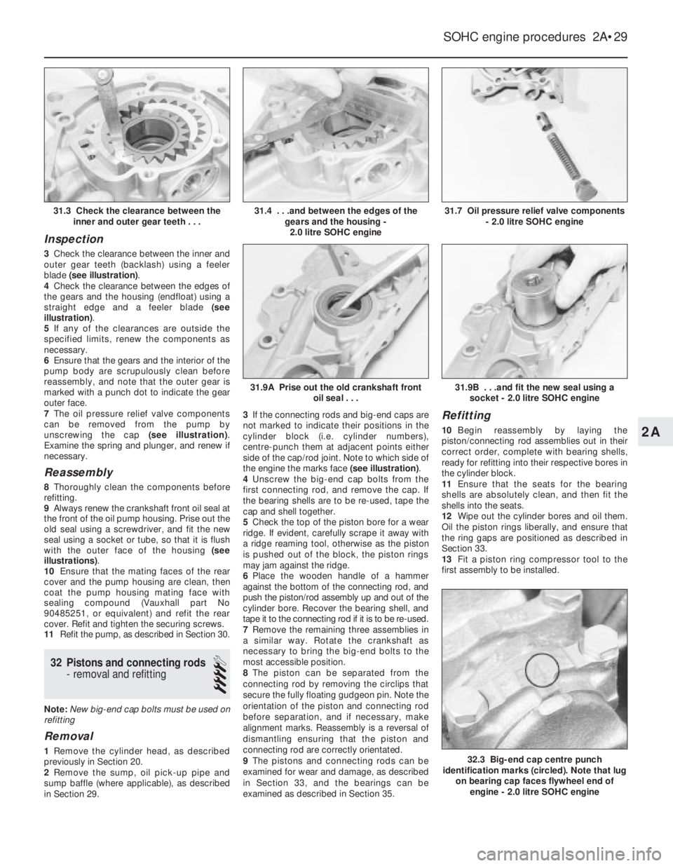
3Check the clearance between the inner and
outer gear teeth (backlash) using a feeler
blade (see illustration).
4Check the clearance between the edges of
the gears and the housing (endfloat) using a
straight edge and a feeler blade (see
illustration).
5If any of the clearances are outside the
specified limits, renew the components as
necessary.
6Ensure that the gears and the interior of the
pump body are scrupulously clean before
reassembly, and note that the outer gear is
marked with a punch dot to indicate the gear
outer face.
7The oil pressure relief valve components
can be removed from the pump by
unscrewing the cap (see illustration).
Examine the spring and plunger, and renew if
necessary.
Reassembly
8Thoroughly clean the components before
refitting.
9Always renew the crankshaft front oil seal at
the front of the oil pump housing. Prise out the
old seal using a screwdriver, and fit the new
seal using a socket or tube, so that it is flush
with the outer face of the housing (see
illustrations).
10Ensure that the mating faces of the rear
cover and the pump housing are clean, then
coat the pump housing mating face with
sealing compound (Vauxhall part No
90485251, or equivalent) and refit the rear
cover. Refit and tighten the securing screws.
11Refit the pump, as described in Section 30.
32Pistons and connecting rods
- removal and refitting
4
Note: New big-end cap bolts must be used on
refitting
Removal
1Remove the cylinder head, as described
previously in Section 20.
2Remove the sump, oil pick-up pipe and
sump baffle (where applicable), as described
in Section 29.3If the connecting rods and big-end caps are
not marked to indicate their positions in the
cylinder block (i.e. cylinder numbers),
centre-punch them at adjacent points either
side of the cap/rod joint. Note to which side of
the engine the marks face (see illustration).
4Unscrew the big-end cap bolts from the
first connecting rod, and remove the cap. If
the bearing shells are to be re-used, tape the
cap and shell together.
5Check the top of the piston bore for a wear
ridge. If evident, carefully scrape it away with
a ridge reaming tool, otherwise as the piston
is pushed out of the block, the piston rings
may jam against the ridge.
6Place the wooden handle of a hammer
against the bottom of the connecting rod, and
push the piston/rod assembly up and out of the
cylinder bore. Recover the bearing shell, and
tape it to the connecting rod if it is to be re-used.
7Remove the remaining three assemblies in
a similar way. Rotate the crankshaft as
necessary to bring the big-end bolts to the
most accessible position.
8The piston can be separated from the
connecting rod by removing the circlips that
secure the fully floating gudgeon pin. Note the
orientation of the piston and connecting rod
before separation, and if necessary, make
alignment marks. Reassembly is a reversal of
dismantling ensuring that the piston and
connecting rod are correctly orientated.
9The pistons and connecting rods can be
examined for wear and damage, as described
in Section 33, and the bearings can be
examined as described in Section 35.
Refitting
10Begin reassembly by laying the
piston/connecting rod assemblies out in their
correct order, complete with bearing shells,
ready for refitting into their respective bores in
the cylinder block.
11Ensure that the seats for the bearing
shells are absolutely clean, and then fit the
shells into the seats.
12Wipe out the cylinder bores and oil them.
Oil the piston rings liberally, and ensure that
the ring gaps are positioned as described in
Section 33.
13Fit a piston ring compressor tool to the
first assembly to be installed.
SOHC engine procedures 2A•29
31.7 Oil pressure relief valve components
- 2.0 litre SOHC engine
32.3 Big-end cap centre punch
identification marks (circled). Note that lug
on bearing cap faces flywheel end of
engine - 2.0 litre SOHC engine
31.9B . . .and fit the new seal using a
socket - 2.0 litre SOHC engine31.9A Prise out the old crankshaft front
oil seal . . .
31.4 . . .and between the edges of the
gears and the housing -
2.0 litre SOHC engine31.3 Check the clearance between the
inner and outer gear teeth . . .
2A
Page 228 of 525

7If any of the ring end gaps exceed the
specified tolerance, the relevant rings will have
to be renewed, and if the ring grooves in the
pistons are worn, new pistons may be required.
8Clean out the piston ring grooves using a
piece of old piston ring as a scraper. Take
care not to scratch the surface of the pistons.
Protect your fingers, piston ring edges are
sharp. Also probe the groove oil return holes,
to ensure that they are not blocked.
9Check the cylinder bores for signs of wear
ridges towards the top of the bores. If wear
ridges are evident, and new piston rings are
being fitted, the top ring must be stepped to
clear the wear ridge, or the bore must be
de-ridged using a scraper.
10Fit the oil control ring sections with the
lower steel ring gap offset 25 to 50 mm to the
right of the spreader ring gap, and the upper
steel ring gap offset by the same distance to
the left of the spreader ring gap.
11Fit the lower compression ring, noting that
the ring is tapered or stepped. The ring should
be fitted with the word “TOP” uppermost.
12Fit the upper compression ring, and offset
the ring gap by 180°to the lower compression
ring gap. If a stepped ring is being fitted, fit
the ring with the smaller diameter of the step
uppermost.
13If new pistons are to be fitted, they must
be selected from the grades available, after
measuring the cylinder bores as described in
Section 36.
14Normally the appropriate oversize pistons
are supplied by the dealer when the block is
rebored.15Whenever new piston rings are being
installed, the glaze on the original cylinder
bores should be “broken”, using either
abrasive paper or a glaze-removing tool in an
electric drill. If abrasive paper is used, use
strokes at 60°to the bore centre line, to create
a cross-hatching effect.
34Crankshaft and bearings -
removal and refitting
4
Note: New main bearing cap bolts must be
used on refitting
Removal
1With the engine removed from the vehicle,
continue as follows.
2Remove the cylinder head, as described
previously in Section 20.
3Remove the sump, oil pick-up pipe and
sump baffle (where applicable), as described
in Section 29.
4Remove the oil pump, as described in
Section 30.
5Remove the flywheel or flexplate (if
applicable), as described in Sections 25 and
26.
6Remove the pistons and connecting rods,
as described in Section 32.
7Invert the engine so that it is standing on
the top face of the cylinder block.
8The main bearing caps are numbered 1 to 4
from the timing belt end of the engine. The
rear (flywheel end) cap is not marked. Toensure that the caps are refitted the correct
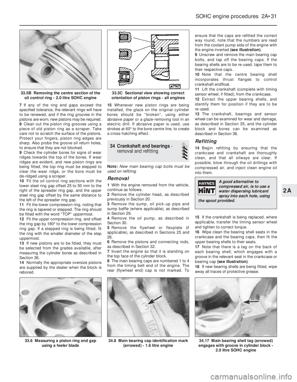
way round, note that the numbers are read
from the coolant pump side of the engine with
the engine inverted (see illustration).
9Unscrew and remove the main bearing cap
bolts, and tap off the bearing caps. If the
bearing shells are to be re-used, tape them to
their respective caps.
10Note that the centre bearing shell
incorporates thrust flanges to control
crankshaft endfloat.
11Lift the crankshaft (complete with timing
sensor wheel, if fitted), from the crankcase.
12Extract the upper bearing shells, and
identify them for position if they are to be
re-used.
13The crankshaft, bearings and sensor
wheel can be examined for wear and damage,
as described in Section 35, and the cylinder
block and bores can be examined as
described in Section 36.
Refitting
14Begin refitting by ensuring that the
crankcase and crankshaft are thoroughly
clean, and that all oilways are clear. If
possible, blow through the oil drillings with
compressed air, and inject clean engine oil
into them.
15If the crankshaft is being replaced, where
applicable, transfer the timing sensor wheel
and tighten to correct torque.
16Wipe clean the bearing shell seats in the
crankcase and the bearing caps, then fit the
upper bearing shells to their seats.
17Note that there is a tag on the back of
each bearing shell, which engages with a
groove in the relevant seat in the crankcase or
bearing cap (see illustration).
18If new bearing shells are being fitted, wipe
away all traces of protective grease.
SOHC engine procedures 2A•31
33.6 Measuring a piston ring end gap
using a feeler blade34.8 Main bearing cap identification mark
(arrowed) - 1.6 litre engine34.17 Main bearing shell tag (arrowed)
engages with groove in cylinder block -
2.0 litre SOHC engine
33.5C Sectional view showing correct
orientation of piston rings - all engines33.5B Removing the centre section of the
oil control ring - 2.0 litre SOHC engine
2A
A good alternative to
compressed air, is to use a
water dispersing lubricant
spray into each hole, using
the spout provided.