sunroof OPEL VECTRA 1988 Service User Guide
[x] Cancel search | Manufacturer: OPEL, Model Year: 1988, Model line: VECTRA, Model: OPEL VECTRA 1988Pages: 525, PDF Size: 58.26 MB
Page 116 of 525
4Certain models may have additional
underbody shields and splashguards fitted,
which may be attached to the wheel arch liners.
32Engine undershield (DOHC
models) - removal and
refitting
2
Removal
1Apply the handbrake, then jack up the front
of the vehicle, and support on axle stands
(see “Jacking and Vehicle Support”).
2Extract the two securing screws, and
remove the oil filter access panel.
3Working around the edges of the splash
shield, remove the self tapping screws that
secure the shield to the body, noting that
some of the screws also secure the wheel
arch liners.
4With the help of an assistant, pull the shield
from the vehicle, and place it to one side to
avoid damage.
Refitting
5Refitting is a reversal of removal.
33Fuel filler flap -removal and
refitting
2
Removal
1Open the flap for access to the four screws
securing the flap to the rear wing.2Remove the securing screws, and withdraw
the flap.
Refitting
3Refitting is a reversal of removal.
34Sunroof components -
removal and refitting
4
Note:The sunroof is a complex piece of
equipment consisting of a large number of
components. It is strongly recommended that
the sunroof mechanism is not disturbed unless
necessary. If the sunroof mechanism is faulty, or
requires overhaul, consult a dealer for advice.
Glass panel
Removal
1Push the sunshade fully rearwards, and
open the glass panel halfway.
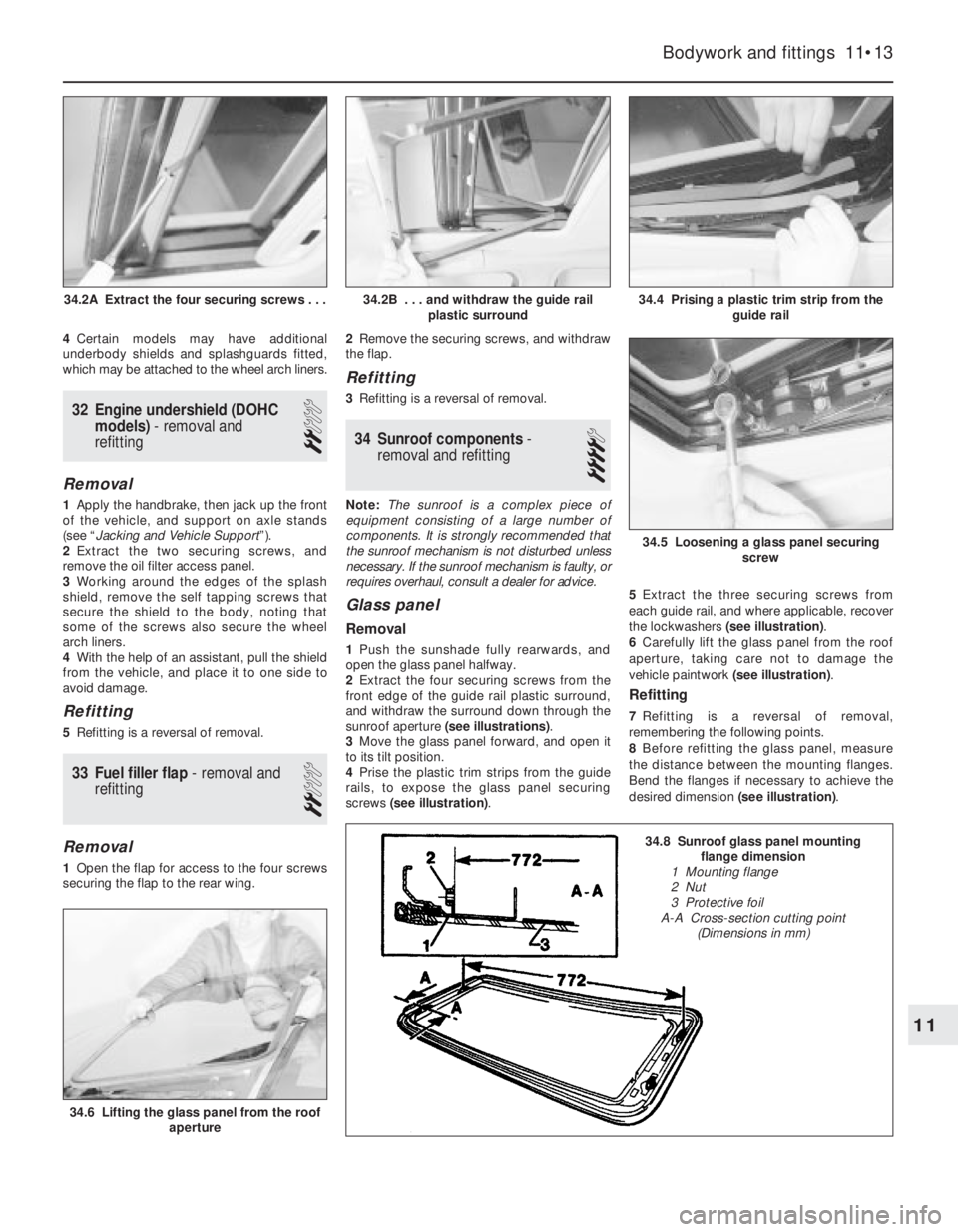
2Extract the four securing screws from the
front edge of the guide rail plastic surround,
and withdraw the surround down through the
sunroof aperture (see illustrations).
3Move the glass panel forward, and open it
to its tilt position.
4Prise the plastic trim strips from the guide
rails, to expose the glass panel securing
screws (see illustration).5Extract the three securing screws from
each guide rail, and where applicable, recover
the lockwashers (see illustration).
6Carefully lift the glass panel from the roof
aperture, taking care not to damage the
vehicle paintwork (see illustration).
Refitting
7Refitting is a reversal of removal,
remembering the following points.
8Before refitting the glass panel, measure
the distance between the mounting flanges.
Bend the flanges if necessary to achieve the
desired dimension (see illustration).
Bodywork and fittings 11•13
34.4 Prising a plastic trim strip from the
guide rail
34.6 Lifting the glass panel from the roof
aperture
34.5 Loosening a glass panel securing
screw
34.2B . . . and withdraw the guide rail
plastic surround34.2A Extract the four securing screws . . .
11
34.8 Sunroof glass panel mounting
flange dimension
1 Mounting flange
2 Nut
3 Protective foil
A-A Cross-section cutting point
(Dimensions in mm)
Page 117 of 525
9Where applicable, ensure that the glass
panel securing screw lockwashers engage
with the locating pins on the guide rails.
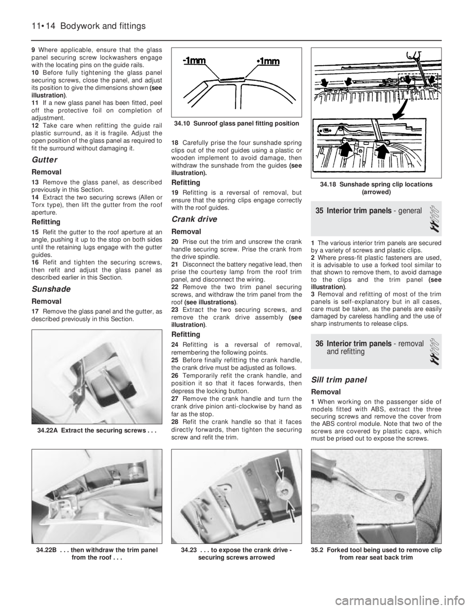
10Before fully tightening the glass panel
securing screws, close the panel, and adjust
its position to give the dimensions shown (see
illustration).
11If a new glass panel has been fitted, peel
off the protective foil on completion of
adjustment.
12Take care when refitting the guide rail
plastic surround, as it is fragile. Adjust the
open position of the glass panel as required to
fit the surround without damaging it.
Gutter
Removal
13Remove the glass panel, as described
previously in this Section.
14Extract the two securing screws (Allen or
Torx type), then lift the gutter from the roof
aperture.
Refitting
15Refit the gutter to the roof aperture at an
angle, pushing it up to the stop on both sides
until the retaining lugs engage with the gutter
guides.
16Refit and tighten the securing screws,
then refit and adjust the glass panel as
described earlier in this Section.
Sunshade
Removal
17Remove the glass panel and the gutter, as
described previously in this Section. 18Carefully prise the four sunshade spring
clips out of the roof guides using a plastic or
wooden implement to avoid damage, then
withdraw the sunshade from the guides (see
illustration).
Refitting
19Refitting is a reversal of removal, but
ensure that the spring clips engage correctly
with the roof guides.
Crank drive
Removal
20Prise out the trim and unscrew the crank
handle securing screw. Prise the crank from
the drive spindle.
21Disconnect the battery negative lead, then
prise the courtesy lamp from the roof trim
panel, and disconnect the wiring.
22Remove the two trim panel securing
screws, and withdraw the trim panel from the
roof (see illustrations).
23Extract the two securing screws, and
remove the crank drive assembly (see
illustration).
Refitting
24Refitting is a reversal of removal,
remembering the following points.
25Before finally refitting the crank handle,
the crank drive must be adjusted as follows.
26Temporarily refit the crank handle, and
position it so that it faces forwards, then
depress the locking button.
27Remove the crank handle and turn the
crank drive pinion anti-clockwise by hand as
far as the stop.
28Refit the crank handle so that it faces
directly forwards, then tighten the securing
screw and refit the trim.
35Interior trim panels -general
2
1The various interior trim panels are secured
by a variety of screws and plastic clips.
2Where press-fit plastic fasteners are used,
it is advisable to use a forked tool similar to
that shown to remove them, to avoid damage
to the clips and the trim panel (see
illustration).
3Removal and refitting of most of the trim
panels is self-explanatory but in all cases,
care must be taken, as the panels are easily
damaged by careless handling and the use of
sharp instruments to release clips.
36Interior trim panels -removal
and refitting
2
Sill trim panel
Removal
1When working on the passenger side of
models fitted with ABS, extract the three
securing screws and remove the cover from
the ABS control module. Note that two of the
screws are covered by plastic caps, which
must be prised out to expose the screws.
11•14Bodywork and fittings
34.22A Extract the securing screws . . .
35.2 Forked tool being used to remove clip
from rear seat back trim34.23 . . . to expose the crank drive -
securing screws arrowed34.22B . . . then withdraw the trim panel
from the roof . . .
34.18 Sunshade spring clip locations
(arrowed)
34.10 Sunroof glass panel fitting position
Page 122 of 525
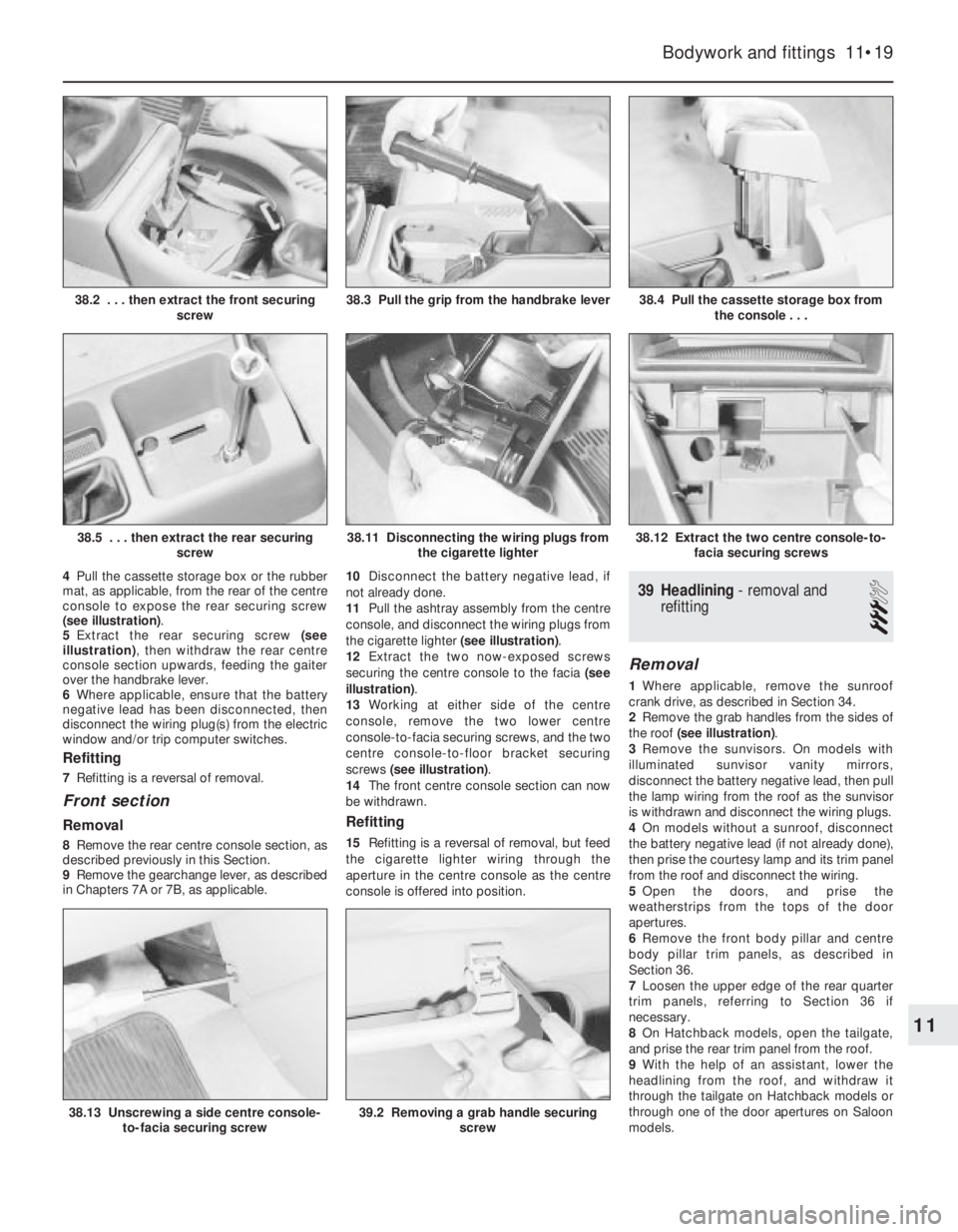
4Pull the cassette storage box or the rubber
mat, as applicable, from the rear of the centre
console to expose the rear securing screw
(see illustration).
5Extract the rear securing screw (see
illustration), then withdraw the rear centre
console section upwards, feeding the gaiter
over the handbrake lever.
6Where applicable, ensure that the battery
negative lead has been disconnected, then
disconnect the wiring plug(s) from the electric
window and/or trip computer switches.
Refitting
7Refitting is a reversal of removal.
Front section
Removal
8Remove the rear centre console section, as
described previously in this Section.
9Remove the gearchange lever, as described
in Chapters 7A or 7B, as applicable. 10Disconnect the battery negative lead, if
not already done.
11Pull the ashtray assembly from the centre
console, and disconnect the wiring plugs from
the cigarette lighter (see illustration).
12Extract the two now-exposed screws
securing the centre console to the facia (see
illustration).
13Working at either side of the centre
console, remove the two lower centre
console-to-facia securing screws, and the two
centre console-to-floor bracket securing
screws (see illustration).
14The front centre console section can now
be withdrawn.
Refitting
15Refitting is a reversal of removal, but feed
the cigarette lighter wiring through the
aperture in the centre console as the centre
console is offered into position.
39Headlining -removal and
refitting
3
Removal
1Where applicable, remove the sunroof
crank drive, as described in Section 34.
2Remove the grab handles from the sides of
the roof (see illustration).
3Remove the sunvisors. On models with
illuminated sunvisor vanity mirrors,
disconnect the battery negative lead, then pull
the lamp wiring from the roof as the sunvisor
is withdrawn and disconnect the wiring plugs.
4On models without a sunroof, disconnect
the battery negative lead (if not already done),
then prise the courtesy lamp and its trim panel
from the roof and disconnect the wiring.
5Open the doors, and prise the
weatherstrips from the tops of the door
apertures.
6Remove the front body pillar and centre
body pillar trim panels, as described in
Section 36.
7Loosen the upper edge of the rear quarter
trim panels, referring to Section 36 if
necessary.
8On Hatchback models, open the tailgate,
and prise the rear trim panel from the roof.
9With the help of an assistant, lower the
headlining from the roof, and withdraw it
through the tailgate on Hatchback models or
through one of the door apertures on Saloon
models.
Bodywork and fittings 11•19
38.4 Pull the cassette storage box from
the console . . .
38.12 Extract the two centre console-to-
facia securing screws38.11 Disconnecting the wiring plugs from
the cigarette lighter
38.3 Pull the grip from the handbrake lever38.2 . . . then extract the front securing
screw
11
38.5 . . . then extract the rear securing
screw
38.13 Unscrewing a side centre console-
to-facia securing screw39.2 Removing a grab handle securing
screw
Page 123 of 525
Refitting
10Refitting is a reversal of removal, but
where applicable, refit the sunroof crank drive,
as described in Section 34.
40Seats (without tensioners) -
removal and refitting
3
Front seats
Removal
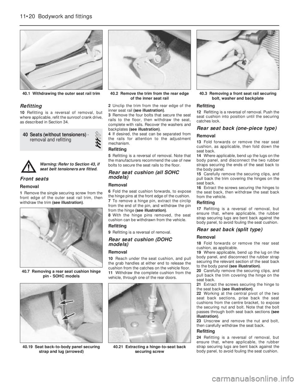
1Remove the single securing screw from the
front edge of the outer seat rail trim, then
withdraw the trim (see illustration).2Unclip the trim from the rear edge of the
inner seat rail (see illustration).
3Remove the four bolts that secure the seat
rails to the floor, then withdraw the seat,
complete with rails. Recover the washers and
backplates (see illustration).
4If desired, the seat can be separated from
the rails for attention to the adjustment
mechanism.
Refitting
5Refitting is a reversal of removal. Note that
the manufacturers recommend the use of new
bolts to secure the seat rails to the floor.
Rear seat cushion (all SOHC
models)
Removal
6Fold the seat cushion forwards, to expose
the hinge pins at the front edge of the cushion.
7To remove a hinge pin, extract the circlip
from the end of the pin, and withdraw the pin
from the hinge (see illustration).
8With the hinge pins removed, the seat
cushion can be withdrawn from the vehicle.
Refitting
9Refitting is a reversal of removal.
Rear seat cushion (DOHC
models)
Removal
10Reach under the seat cushion, and pull
the grab handles at either end to release the
cushion from the catches on the vehicle floor.
11Withdraw the complete cushion from the
vehicle, through one of the rear doors.
Refitting
12Refitting is a reversal of removal. Push the
seat cushion into position until the securing
catches lock.
Rear seat back (one-piece type)
Removal
13Fold forwards or remove the rear seat
cushion, as applicable, then fold down the
seat back.
14Where applicable, bend up the lugs on the
body panel, and disconnect the two rubber
straps securing the ends of the seat back to
the body panel.
15Carefully remove the securing clips, and
pull back the trim covering the hinges on the
seat back.
16Extract the screws securing the hinges to
the seat back, then withdraw the seat back
from the vehicle.
Refitting
17Refitting is a reversal of removal, but
ensure that, where applicable, the rubber
strap securing lugs are bent back against the
body panel, to avoid fouling the seat cushion.
Rear seat back (split type)
Removal
18Fold forwards or remove the rear seat
cushion, as applicable.
19Where applicable, bend up the lug on the
body panel, and disconnect the rubber strap
securing the relevant section of the seat back
to the body panel (see illustration).
20Carefully remove the securing clips, and
pull back the trim covering the hinge on the
seat back.
21Extract the screws securing the hinge to
the seat back (see illustration).
22Working at the central pivot of the two
seat back sections, prise back the seat
cushions from the centre bracket, to expose
the securing nut and bolt. Note that the bolt
passes through both seat back sections (see
illustration).
23Unscrew and remove the nut and bolt,
then carefully withdraw the seat back.
Refitting
24Refitting is a reversal of removal, but
ensure that, where applicable, the rubber
strap securing lugs are bent back against the
body panel, to avoid fouling the seat cushion.
11•20Bodywork and fittings
40.1 Withdrawing the outer seat rail trim40.3 Removing a front seat rail securing
bolt, washer and backplate
40.7 Removing a rear seat cushion hinge
pin - SOHC models
40.21 Extracting a hinge-to-seat back
securing screw40.19 Seat back-to-body panel securing
strap and lug (arrowed)
40.2 Remove the trim from the rear edge
of the inner seat rail
Warning: Refer to Section 43, if
seat belt tensioners are fitted.
Page 266 of 525
Pierburg 2E3 carburettor- 4A•5
Piston rings- 2A•30
Piston/connecting rod- 2A•29
Plastic components- 11•3
Potentiometer- 4B•12, 4B•16
Power steering fluid - 0•14, 0•17, 1•2, 1•12
Power steering pump- 10•22
Power steering system bleeding- 10•22
Punctures- 0•8
RRadiator- 3•3
Radiator cooling fan- 3•5
Radiator grille- 11•12
Radio/cassette anti theft system- REF•5
Radio/cassette player- 12•18
Rear hub- 10•10, 10•15
Rear lamps- 12•11
Rear suspension assembly- 10•15
Relays- 12•3
Release bearing (clutch)- 6•6
Repair procedures- REF •4
Respraying- 11•2
Reversing lamp switch- 7A•6
Road test- 1•13
Roll bars- 10•8, 10•13, 10•17
Routine maintenance - 1•1 et seq
SSafety first!- 0•5
Scratches- 11•2
Seat belts- 11•21
Seats- 11•20, 11•22
Seats heated- 12•6
Selector cable (automatics)- 7B•4
Selector lever- 7B•4
Sender unit fuel level- 4A•4, 4B•8
Sender units (temperature gauge)- 3•6
Servicing - see Routine maintenance
Servo unit (braking system)- 9•15
Shock absorber- 10•11
Shoes (brake)- 9•6
Short-circuit finding- 12•2
Spark plugs- 1•3, 1•14, 1•16
Speakers- 12•17
Speedometer cable- 12•18
Speedometer drive- 7A•6
Starter inhibitor switch- 7B•3
Starter motor- 5•8
Starting problems- 0•6
Steering wheel alignment- 10•1, 10•24
Steering- 10•1 et seq
camber - 10•1 10•24
castor - 10•1, 10•24
column - 10•18
damper - 10•21
fault diagnosis - REF•12, REF•17gear - 10•21
power steering system bleeding - 10•22
power steering fluid - 0•17, 1•2
power steering pump - 10•22
shaft rubber coupling - 10•18
tie-rod end - 10•23
toe setting - 10•1, 10•24
wheel - 10•17
wheel bearing - 10•4, 10•9, 10•14
wheel with airbag - 12•20
Stub axle- 10•13
Subframe- 10•5
Sump- 2A•27, 2B•9
Sunroof- 11•13
Sunroof motor- 12•18
Sunroof switch- 12•5
Suspension- 10•1 et seq
anti-roll bars - 10•8, 10•13, 10•17
assembly (rear) - 10•15
coil spring (rear) - 10•12, 10•15
fault diagnosis - REF•12, REF•17
level control system - 10•14
lower arm (front) - 10•7
rear hub - 10•10, 10•15
shock absorber - 10•11
strut (front) - 10•6
stub axle - 10•13
sub frame - 10•5
trailing arms - 10•12, 10•16
wheel bearing - 10•4, 10•9, 10•14
Suspension/steering checks- 1•10
Switches:
brake lamp - 12•5
cooling fan - 3•6
courtesy lamp - 12•5
electric door mirror - 12•5
handbrake warning lamp - 12•5
hazard warning - 12•4
heater blower motor - 12•4
ignition - 12•3
indicator - 12•4
kickdown - 7B•3
lights - 12•4
luggage compartment - 12•5
oil pressure warning lamp - 12•5
push button - 12•4
reversing lamp - 7A•6
starter inhibitor - 7B•3
sunroof - 12•5
TTailgate- 11•5
Temperature gauge sender- 3•6
Temperature sensor (automatics)- 7B•5
Thermostat- 3•4
Throttle cable- 4A•5, 4B•9
Throttle pedal- 4A•5Tie-rod end- 10•23
Timing- 5•2, 5•13
Timing belt- 1•16, 2A•13, 2B•3, 2B•6
Toe setting- 10•1, 10•24
Tools and working facilities- REF•4, REF•6,
REF•7
Towing- 0•9
Trim panel (door)- 11•6
Tyre checks- 0•16, 0•17
Tyre pressures- 0•17
UUnderbody- 11•1
Underbody views- 1•7
Underbonnet views- 0•10, 1•5
Upholstery and carpets- 11•2
VVacuum servo unit (braking system)- 9•15
Valve lifters- 2A•24, 2B•9
Valves- 2A•5, 2B•2
Vehicle identification numbers- REF•3
Ventilation system- 3•1 et seq
Vents- 3•8
WWasher fluid- 0•13, 1•2
Washers- 12•13, 12•15
Water pump- 3•4
Weekly checks- 0•10et seq
Wheelalignment- 10•1, 10•24
Wheel arch liners- 11•12
Wheel bearing- 10•4, 10•9, 10•14
Wheel changing- 0•8
Wheel cylinder- 9•11
Window glass- 11•9
Window regulator- 11•10
Windscreen- 11•9, 11•12
Wiper blades- 0•15, 12•13
Wiper motors- 12•14
Wiring diagrams- 12•22 et seq
Index REF•27
REF