clock OPEL VIVARO B 2018 Manual user
[x] Cancel search | Manufacturer: OPEL, Model Year: 2018, Model line: VIVARO B, Model: OPEL VIVARO B 2018Pages: 237, PDF Size: 5.57 MB
Page 178 of 237
176Vehicle careDaytime running light with LEDs
Daytime running lights consist of
LEDs which cannot be changed.
Consult a workshop in case of a
defective LED.
Fog lights
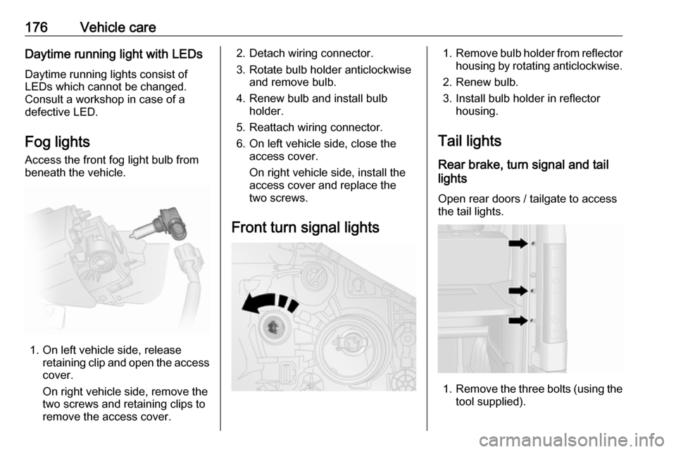
Access the front fog light bulb from
beneath the vehicle.
1. On left vehicle side, release retaining clip and open the accesscover.
On right vehicle side, remove the
two screws and retaining clips to
remove the access cover.
2. Detach wiring connector.
3. Rotate bulb holder anticlockwise and remove bulb.
4. Renew bulb and install bulb holder.
5. Reattach wiring connector.
6. On left vehicle side, close the access cover.
On right vehicle side, install the
access cover and replace the
two screws.
Front turn signal lights1. Remove bulb holder from reflector
housing by rotating anticlockwise.
2. Renew bulb.
3. Install bulb holder in reflector housing.
Tail lights
Rear brake, turn signal and tail
lights
Open rear doors / tailgate to access
the tail lights.
1. Remove the three bolts (using the
tool supplied).
Page 179 of 237
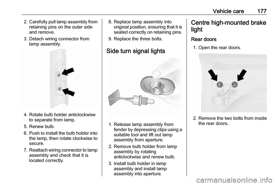
Vehicle care1772.Carefully pull lamp assembly from
retaining pins on the outer side
and remove.
3. Detach wiring connector from lamp assembly.
4. Rotate bulb holder anticlockwiseto separate from lamp.
5. Renew bulb.
6. Push to install the bulb holder into
the lamp, then rotate clockwise to secure.
7. Reattach wiring connector to lamp
assembly and check that it is
located correctly.
8. Replace lamp assembly into original position, ensuring that it isseated correctly on retaining pins.
9. Replace the three bolts.
Side turn signal lights
1. Release lamp assembly from fender by depressing clips using a
suitable tool and lift out lamp
assembly from aperture.
2. Remove bulb holder from lamp assembly by rotating
anticlockwise and renew bulb.
3. Install bulb holder in lamp assembly and install lamp
assembly into aperture.
Centre high-mounted brake
light
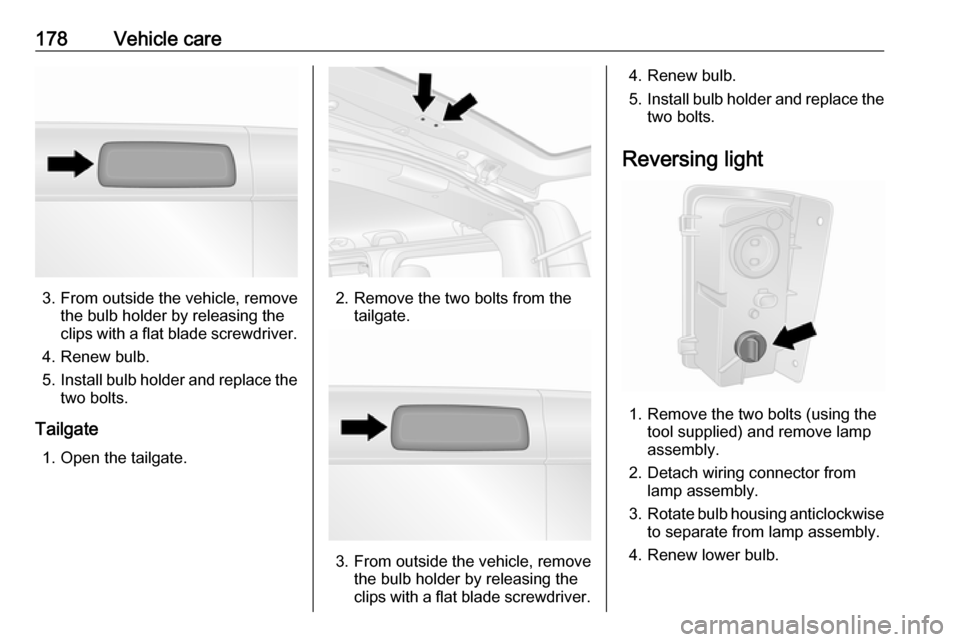
Rear doors 1. Open the rear doors.
2. Remove the two bolts from inside the rear doors.
Page 180 of 237
178Vehicle care
3. From outside the vehicle, removethe bulb holder by releasing the
clips with a flat blade screwdriver.
4. Renew bulb.
5. Install bulb holder and replace the
two bolts.
Tailgate 1. Open the tailgate.2. Remove the two bolts from the tailgate.
3. From outside the vehicle, remove the bulb holder by releasing the
clips with a flat blade screwdriver.
4. Renew bulb.
5. Install bulb holder and replace the
two bolts.
Reversing light
1. Remove the two bolts (using the tool supplied) and remove lamp
assembly.
2. Detach wiring connector from lamp assembly.
3. Rotate bulb housing anticlockwise
to separate from lamp assembly.
4. Renew lower bulb.
Page 181 of 237
Vehicle care1795.Push to install the bulb holder into
the lamp assembly, then rotate
clockwise to secure.
6. Reattach wiring connector to lamp
assembly.
7. Install lamp assembly with the two bolts.
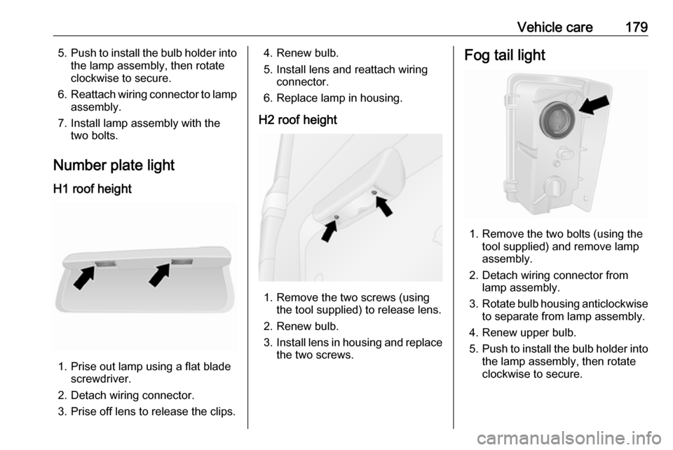
Number plate light
H1 roof height
1. Prise out lamp using a flat blade screwdriver.
2. Detach wiring connector.
3. Prise off lens to release the clips.
4. Renew bulb.
5. Install lens and reattach wiring connector.
6. Replace lamp in housing.
H2 roof height
1. Remove the two screws (using the tool supplied) to release lens.
2. Renew bulb.
3. Install lens in housing and replace
the two screws.
Fog tail light
1. Remove the two bolts (using the tool supplied) and remove lamp
assembly.
2. Detach wiring connector from lamp assembly.
3. Rotate bulb housing anticlockwise
to separate from lamp assembly.
4. Renew upper bulb.
5. Push to install the bulb holder into
the lamp assembly, then rotate
clockwise to secure.
Page 187 of 237
Vehicle care185No.Circuit40Rear power outlet41Starting / Body control module42Heated seats43Tachograph44Windscreen wiper45Heating / Air conditioning
After having changed defective fuses,
replace the trim panel.
Vehicle tools
Tools
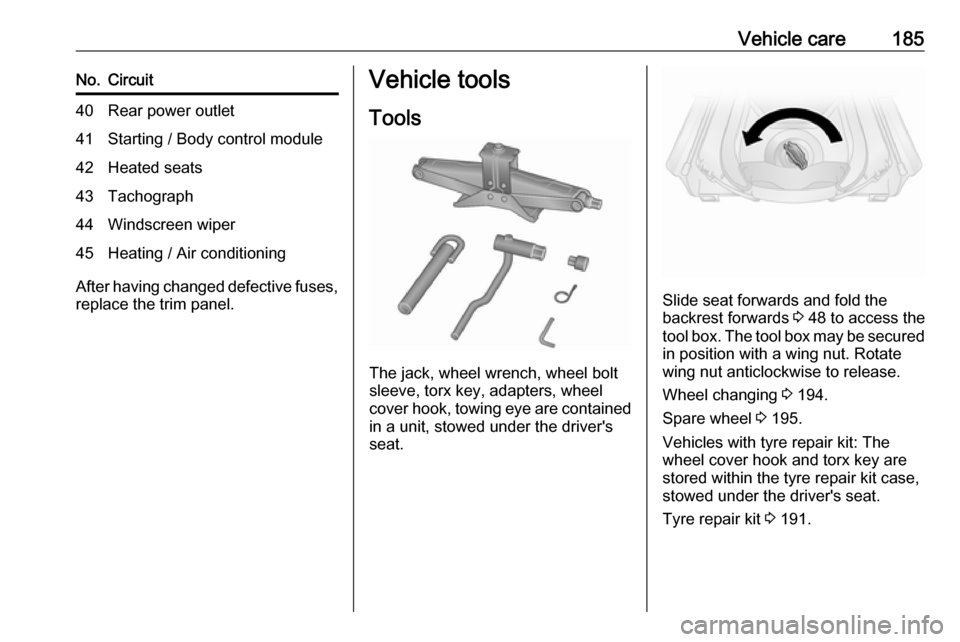
The jack, wheel wrench, wheel bolt
sleeve, torx key, adapters, wheel
cover hook, towing eye are contained
in a unit, stowed under the driver's
seat.
Slide seat forwards and fold the
backrest forwards 3 48 to access the
tool box. The tool box may be secured
in position with a wing nut. Rotate
wing nut anticlockwise to release.
Wheel changing 3 194.
Spare wheel 3 195.
Vehicles with tyre repair kit: The wheel cover hook and torx key are
stored within the tyre repair kit case,
stowed under the driver's seat.
Tyre repair kit 3 191.
Page 196 of 237
194Vehicle careNote
The driving characteristics of the repaired tyre is severely affected,
therefore have this tyre replaced.
If unusual noise is heard or the
compressor becomes hot, turn
compressor off for at least
30 minutes.
Pay attention to storage information
and expiry date on sealant bottle. Its
sealing capability is not guaranteed
after this time.
Replace the used sealant bottle. Dispose of the sealant bottle as
prescribed by applicable laws.
Wheel changing
Some vehicles are equipped with a
tyre repair kit instead of a spare wheel
3 191.
Make the following preparations and
observe the following information:
● Park the vehicle on a level, firm and non-slippery surface. The
front wheels must be in the
straight-ahead position.
● Apply the parking brake and engage first gear or reverse gear.● Remove the spare wheel 3 195.
● Never change more than one wheel at a time.
● Use the jack only to change wheels in case of puncture, not
for a seasonal winter or summer
tyre change.
● The jack is maintenance-free. ● If the ground on which the vehicle
is standing is soft, a solid board
(max. 1 cm thick) should be
placed under the jack.
● Remove heavy objects out of the
vehicle before jacking up.
● No people or animals may be in the vehicle when it is jacked-up.
● Never crawl under a jacked-up vehicle.
● Do not start the engine when the vehicle is raised on the jack.
● Clean wheel bolts / nuts and thread with a clean cloth before
mounting the wheel.9 Warning
Do not grease wheel bolt, wheel
nut and wheel nut cone.
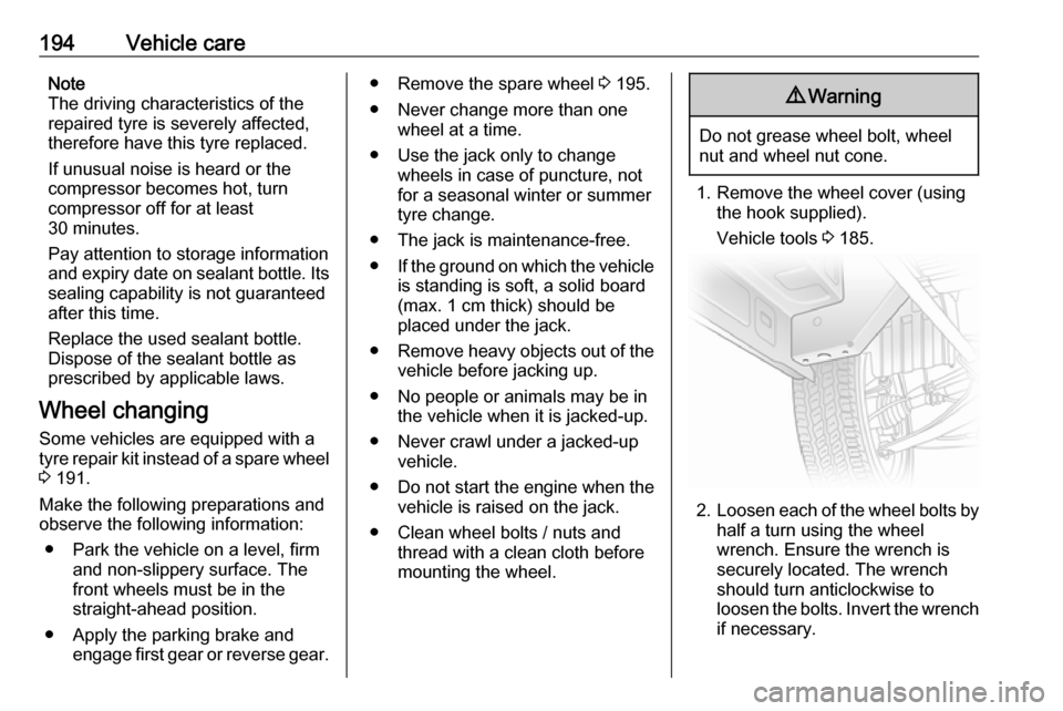
1. Remove the wheel cover (using the hook supplied).
Vehicle tools 3 185.
2. Loosen each of the wheel bolts by
half a turn using the wheel
wrench. Ensure the wrench is
securely located. The wrench
should turn anticlockwise to
loosen the bolts. Invert the wrench if necessary.
Page 197 of 237
Vehicle care195
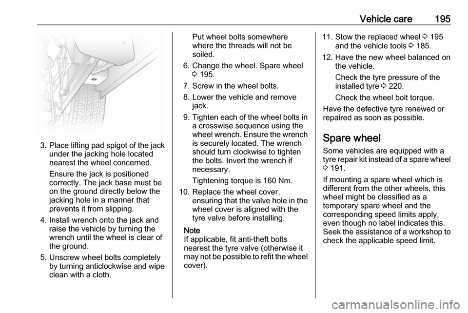
3.Place lifting pad spigot of the jack
under the jacking hole located
nearest the wheel concerned.
Ensure the jack is positioned
correctly. The jack base must be
on the ground directly below the
jacking hole in a manner that
prevents it from slipping.
4. Install wrench onto the jack and raise the vehicle by turning the
wrench until the wheel is clear of
the ground.
5. Unscrew wheel bolts completely by turning anticlockwise and wipe
clean with a cloth.
Put wheel bolts somewhere
where the threads will not be
soiled.
6. Change the wheel. Spare wheel 3 195.
7. Screw in the wheel bolts.
8. Lower the vehicle and remove jack.
9. Tighten each of the wheel bolts in
a crosswise sequence using the
wheel wrench. Ensure the wrench is securely located. The wrench
should turn clockwise to tighten
the bolts. Invert the wrench if
necessary.
Tightening torque is 160 Nm.
10. Replace the wheel cover, ensuring that the valve hole in thewheel cover is aligned with the
tyre valve before installing.
Note
If applicable, fit anti-theft bolts
nearest the tyre valve (otherwise it
may not be possible to refit the wheel
cover).11. Stow the replaced wheel 3 195
and the vehicle tools 3 185.
12. Have the new wheel balanced on the vehicle.
Check the tyre pressure of the
installed tyre 3 220.
Check the wheel bolt torque.
Have the defective tyre renewed or
repaired as soon as possible.
Spare wheel
Some vehicles are equipped with a tyre repair kit instead of a spare wheel
3 191.
If mounting a spare wheel which is
different from the other wheels, this
wheel might be classified as a
temporary spare wheel and the
corresponding speed limits apply,
even though no label indicates this.
Seek the assistance of a workshop to
check the applicable speed limit.
Page 200 of 237
198Vehicle care
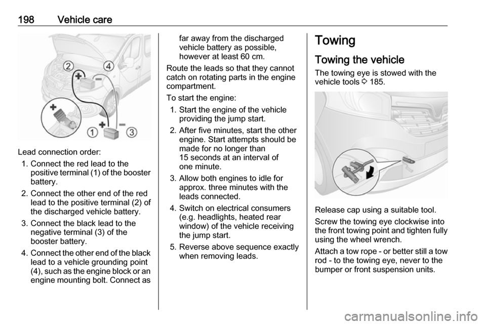
Lead connection order:1. Connect the red lead to the positive terminal (1) of the booster
battery.
2. Connect the other end of the red lead to the positive terminal (2) of
the discharged vehicle battery.
3. Connect the black lead to the negative terminal (3) of the
booster battery.
4. Connect the other end of the black
lead to a vehicle grounding point
(4), such as the engine block or an
engine mounting bolt. Connect as
far away from the discharged
vehicle battery as possible,
however at least 60 cm.
Route the leads so that they cannot
catch on rotating parts in the engine
compartment.
To start the engine: 1. Start the engine of the vehicle providing the jump start.
2. After five minutes, start the other engine. Start attempts should be
made for no longer than
15 seconds at an interval of
one minute.
3. Allow both engines to idle for approx. three minutes with the
leads connected.
4. Switch on electrical consumers (e.g. headlights, heated rear
window) of the vehicle receiving
the jump start.
5. Reverse above sequence exactly when removing leads.Towing
Towing the vehicle The towing eye is stowed with thevehicle tools 3 185.
Release cap using a suitable tool.
Screw the towing eye clockwise into
the front towing point and tighten fully
using the wheel wrench.
Attach a tow rope - or better still a tow rod - to the towing eye, never to the
bumper or front suspension units.
Page 231 of 237

229Charging system .......................... 98
Child locks ................................... 32
Child restraint installation locations ................................... 68
Child restraints.............................. 65
Child restraint systems ................65
Cigarette lighter ........................... 90
Cleaning the vehicle ...................200
Climate control ............................. 17
Climate control systems .............116
Clock ............................................ 88
Coat hooks ................................... 75
Coin holder ................................... 73
Collision damage repair ..............225
Control indicators.......................... 94
Control of the vehicle .................131
Controls ........................................ 85
Controls in steering wheel ............85
Convex shape .............................. 40
Coolant ....................................... 169
Coolant and antifreeze ...............205
Coolant heater ............................ 122
Cooling (A/C) .............................. 117
Cornering light ............................ 110
Cruise control ....................102, 152
Cupholders .................................. 75
Curtain airbag system .................. 64D
Danger, Warnings and Cautions ...4
Dashboard .................................... 10
Daytime running lights ........109, 110
Declaration of conformity ............221
DEF ............................................ 141
Demisting and defrosting ..............17
Diesel exhaust fluid ....................141
Diesel fuel ................................... 159
Diesel fuel filter .......................... 173
Diesel fuel system bleeding .......173
Diesel particle filter ....................140
Directional tyres ..................186, 195
Distance to service .......................93
Document tray .............................. 75
Door locks..................................... 25
Door open .................................. 102
Door panel storage .......................76
Doors ............................................ 32
Double cab ................................... 76
DPF (diesel particle filter) ...........140
Driver assistance systems ..........152
Driver Information Centre ...........102
Driving characteristics and towing tips .............................. 162
Driving economically................... 130
Driving hints ........................ 130, 131
Driving style indicator ...................93E
ECO mode .................................. 130
ecoScoring.................................. 105
Electric adjustment ......................41
Electrical accessories ...................88
Electrical system......................... 181
Electronic climate control system 118
Electronic data recording ..............43
Electronic key system ...................24
Electronic Stability Program 99,
150, 163
Electronic Stability Program off ...99
End-of-life vehicle recovery .......166
Engine air filter............................ 168
Engine air flow indicator .............168
Engine coolant ........................... 169
Engine coolant temperature ........99
Engine data ............................... 210
Engine Drag Torque Control ......150
Engine exhaust .......................... 140
Engine identification ...................208
Engine oil ...........167, 205, 209, 219
Engine oil additives ....................205
Engine oil level .......................... 104
Engine oil pressure ....................100
Engine oil viscosity grades .........205
Enhanced Traction function 149, 150
Entry lighting .............................. 114
Event data recorders ..................225
Exhaust gases ....................140, 198