steering OPEL VIVARO C 2020.25 Manual user
[x] Cancel search | Manufacturer: OPEL, Model Year: 2020.25, Model line: VIVARO C, Model: OPEL VIVARO C 2020.25Pages: 287, PDF Size: 28.79 MB
Page 167 of 287

Driving and operating165
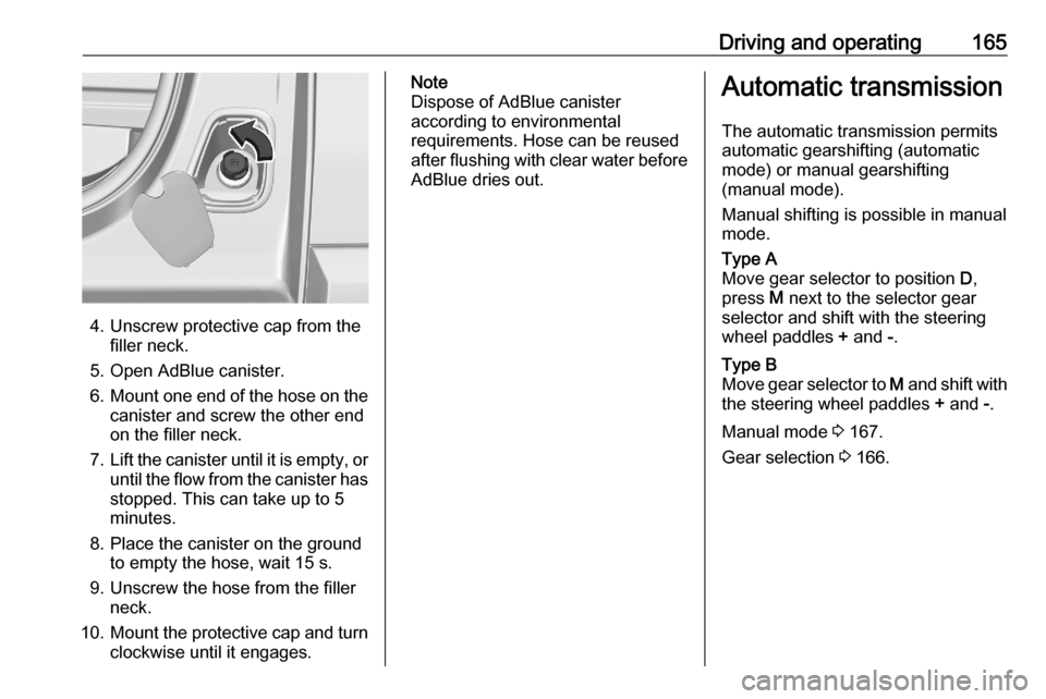
4. Unscrew protective cap from thefiller neck.
5. Open AdBlue canister.
6. Mount one end of the hose on the
canister and screw the other end
on the filler neck.
7. Lift the canister until it is empty, or
until the flow from the canister has stopped. This can take up to 5
minutes.
8. Place the canister on the ground to empty the hose, wait 15 s.
9. Unscrew the hose from the filler neck.
10. Mount the protective cap and turn
clockwise until it engages.
Note
Dispose of AdBlue canister
according to environmental
requirements. Hose can be reused
after flushing with clear water before
AdBlue dries out.Automatic transmission
The automatic transmission permits
automatic gearshifting (automatic
mode) or manual gearshifting
(manual mode).
Manual shifting is possible in manual
mode.Type A
Move gear selector to position D,
press M next to the selector gear
selector and shift with the steering
wheel paddles + and -.Type B
Move gear selector to M and shift with
the steering wheel paddles + and -.
Manual mode 3 167.
Gear selection 3 166.
Page 169 of 287

Driving and operating167R:reverse gear, engage only when
the vehicle is stationaryN:neutralA:automatic modeM:manual mode
The engine can only be started with the gear selector in position N. When
position N is selected, press the brake
pedal and start the engine.
Do not accelerate while engaging a
gear. Never depress the accelerator
pedal and brake pedal at the same
time.
When a gear is engaged, the vehicle
slowly begins to creep when the
brake is released.
Engine braking To utilise the engine braking effect,select a lower gear when driving
downhill.
Parking
Type A:
Apply the parking brake and select P.Type B
Apply the parking brake and select
N or leave the selected gear selector
position.
Manual mode 1. Activate manual mode a) Automatic transmission type A:Manual mode M can be activated
from position D in each driving
situation and speed.
Press button M.
b) Automatic transmission type B:
Move gear selector to position M
if vehicle is at a standstill.
2. Pull steering wheel paddles to select gears manually.
Pull right steering wheel paddle + to
shift to a higher gear.
Pull left steering wheel paddle - to
shift to a lower gear.
Multiple pulls allow gears to be
skipped.
The selected gear is indicated in the
instrument cluster.
If a higher gear is selected when
vehicle speed is too low, or a lower
gear when vehicle speed is too high,
the shift is not executed. This can
cause a message in the Driver
Information Centre.
Page 190 of 287

188Driving and operating9Warning
Forward collision alert is just a
warning system and does not
apply the brakes. When
approaching a vehicle ahead too
rapidly, there may not be enough
time to avoid a collision.
The driver accepts full
responsibility for the appropriate
following distance based on traffic, weather and visibility conditions.
The complete attention of the
driver is always required while
driving. The driver must always be
ready to take action and apply the
brakes.
Caution
The colour lighting of this control
indicator does not correspond to
local traffic laws on following
distance. The driver bears full
responsibility for maintaining safe
following distance according to
applicable traffic rules, weather
and road conditions etc. at all
times.
Selecting the alert sensitivity
The alert sensitivity has to be set to
close, normal or distant in the vehicle personalisation menu 3 124.
The chosen setting will remain until it
is changed. The alert timing will vary
based on vehicle speed. The faster
the vehicle speed, the farther away
the alert will occur. Consider traffic
and weather conditions when
selecting the alert timing.
Deactivation The system can only be deactivated
by deactivating the active emergency
braking in the vehicle personalisation
3 124.
System limitations
Forward collision alert is designed to
warn on vehicles only, but may react
also to other objects.
In the following cases, forward
collision alert may not detect a vehicle ahead or sensor performance is
limited:
● driving on winding or hilly roads
● driving during nighttime
● weather limits visibility, such as fog, rain, or snow
● the sensor in the windscreen is blocked by snow, ice, slush, mud,dirt etc.
● the windscreen is damaged or affected by foreign objects, e.g.
stickers
Active emergency braking
Active emergency braking can help to reduce the damage and injury from
crashes with vehicles, pedestrians
and obstacles directly ahead, when a
collision can no longer be avoided
either by manual braking or by
steering. Before the active
emergency braking applies, the driver is warned by the forward collision
alert or the front pedestrian protection
alert.
Page 199 of 287

Driving and operating197The system uses:● rear camera, installed in the tailgate
● ultrasonic parking assist sensors in the rear bumper
The screen in the Info Display is
divided into two parts. On the right
there is a view from above the vehicle,
and on the left there is the view from
the rear displayed. The parking
sensors complete the information on
the view from above the vehicle.
Change the volume of the acoustic
signals by pressing 4 in the right
lower zone of the display.
Activation
Panoramic view system is activated
by:
● engaging reverse gear
● driving up to 10 km/h
Functionality
Different views can be selected in the left part of the display. Change the
type of view at any time during a
manoeuvre by touching in the left
lower zone of the display:
● Standard view
● AUTO Mode
● Zoom view
● 180° view
The display is immediately updated
with the type of view selected.
AUTO Mode is activated by default. In
this mode, the system selects the
best view, standard or zoom, to
display according to the information
from the parking sensors.
The state of the system is not kept in
memory when the ignition is switched
off.Rear view / Standard view
The area behind the vehicle is
displayed in the screen. The vertical
lines represent the width of the
vehicle with mirrors unfolded. The
direction of the lines changes with the position of the steering wheel.
The first horizontal line represents a
distance of about 30 cm beyond the
edge of vehicle's rear bumper. The
upper horizontal lines represent
distances of about 1 and 2 m beyond
the edge of the vehicle's rear bumper.
This view is available in AUTO Mode
or in the view selection menu.
Page 204 of 287

202Driving and operatingdriver is based on the trajectory
variations of the vehicle compared to the lane markings.9 Warning
The system cannot replace the
need for vigilance on the part of
the driver. Taking a break is
recommended as soon as feeling tired or at least every 2 hours. Do
not take the steering wheel when
feeling tired.
Activation or Deactivation
The system can be activated or
deactivated in the vehicle
personalisation 3 124.
The state of the system stays in
memory when the ignition is switched off.
Driving time alert
The driver gets notified by a pop-up reminder symbol Y in the Driver
Information Centre simultaneously with an acoustic alert if the driver has
not taken a break after 2 hours of
driving at a speed above 65 km/h. The
alert is repeated hourly until the
vehicle is stopped, no matter how
vehicle speed evolves.
The counting of driving time alert is
reset if one of the following conditions
is met:
● The vehicle has been stationary for more than 15 minutes with theengine running.
● The ignition has been switched off for a few minutes.
● The driver's seat belt has been unfastened and the driver's door
is open.
Note
If the vehicle speed drops below 65 km/h, the system is paused. The
driving time is counted again once
the speed is above 65 km/h.
Driver drowsiness detection
The system monitors the driver's level
of vigilance. A camera at the top of the
windscreen detects variations in
trajectory compared to the lane
markings. This system is particularly
suited to fast roads (speed higher
than 65 km/h).If the trajectory of the vehicle
suggests a certain level of
drowsiness or inattention by the
driver, the system triggers the first
level of alert. The driver is notified by
a message and an audible signal is
given.
After three first level alerts, the
system triggers a new alert with a
message, accompanied by a more
pronounced audible signal.
In certain driving conditions (poor
road surface or strong winds), the
system may give alerts independent of the driver's level of vigilance.
The driver drowsiness detection is
reinitialised when the ignition has
been switched off for a few minutes or the speed remains below 65 km/h for
a few minutes.
System limitationsIn the following situations, the system
may not operate properly or even not
operate at all:
● poor visibility caused by inadequate lighting of the
roadway, falling snow, heavy
rain, dense fog etc.
Page 208 of 287

206Driving and operatingFor trailers with low driving stability
and caravan trailers, the use of an
oscillation damper is strongly
recommended.
If the trailer starts snaking, drive more slowly, do not attempt to correct the
steering and brake sharply if
necessary.
When driving downhill, drive in the
same gear as if driving uphill and
drive at a similar speed.
If the outside temperature exceeds
37 °C, reduce the load on the trailer
to protect the engine of the vehicle.
At high outside temperatures it is
recommended to leave the engine
running for one or two minutes after
having stopped the vehicle in order to
faciliate cooling.
Adjust tyre pressure to the value
specified for full load 3 271.
Towing a trailer increases the braking
distance of the vehicle. To limit the
heating of the brakes, it is
recommended to use the braking
effect of the engine.By driving uphill, the temperature of
the coolant is increased. To reduce
heating, drive at a reduced speed and
pay attention to the coolant
temperature. If the control indicator
2 of the engine coolant temperature
gauge illuminates, stop the vehicle
and switch off engine as soon as
possible.
Trailer towing Trailer loadsThe permissible trailer loads are
vehicle and engine-dependent
maximum values which must not be
exceeded. The actual trailer load is
the difference between the actual
gross weight of the trailer and the
actual coupling socket load with the
trailer coupled.
The permissible trailer loads are
specified in the vehicle documents. In general, they are valid for gradients
up to 12%.
The permissible trailer load applies
up to the specified incline and at sea
level. Since engine power decreases
as altitude increases due to the airbecoming thinner, therefore reducing
climbing ability, the permissible gross
train weight also decreases by 10%
for every 1000 metres of altitude. The gross train weight does not have to be
reduced when driving on roads with
slight inclines (less than 8%, e.g.
motorways).
The permissible gross train weight
must not be exceeded. This weight is
specified on the identification plate
3 264.
When distributing the loads in the trailer, heavy objects should be
placed as close as possible to the
axle.
Vertical coupling load
The vertical coupling load is the load
exerted by the trailer on the coupling
ball. It can be varied by changing the
weight distribution when loading the
trailer.
The maximum permissible vertical
coupling load is specified on the
towing equipment identification plate
and in the vehicle documents.
Page 212 of 287

210Driving and operating
3. Connect the trailer plug to thesocket and fasten the breakaway
stopping cable to the eye on the
carrier.
Trailer stability assist If the system detects snaking
movements, engine power is reduced
and the vehicle / trailer combination is
selectively braked until the snaking
ceases. While system is working keep
steering wheel as still as possible.
Trailer stability assist is a function of
the Electronic Stability Control 3 171.
Page 220 of 287

218Vehicle careDischarge protection
Battery voltage
When the vehicle battery voltage is
running low, a warning message will
appear in the Driver Information
Centre.
When the vehicle is being driven, the
load reduction function temporarily
deactivates certain functions, such as
the air conditioning, the heated rear
window, heated steering wheel, etc.
The deactivated functions are
reactivated automatically as soon as
conditions permit.
Idle boost
If charging of the vehicle battery is
required due to battery condition, the
power output of the generator must be increased. This will be achieved by
an idle boost which may be audible.
A message appears in the Driver
Information Centre.
Power outlet
The power outlets are deactivated in
the event of low vehicle battery
voltage.Warning label
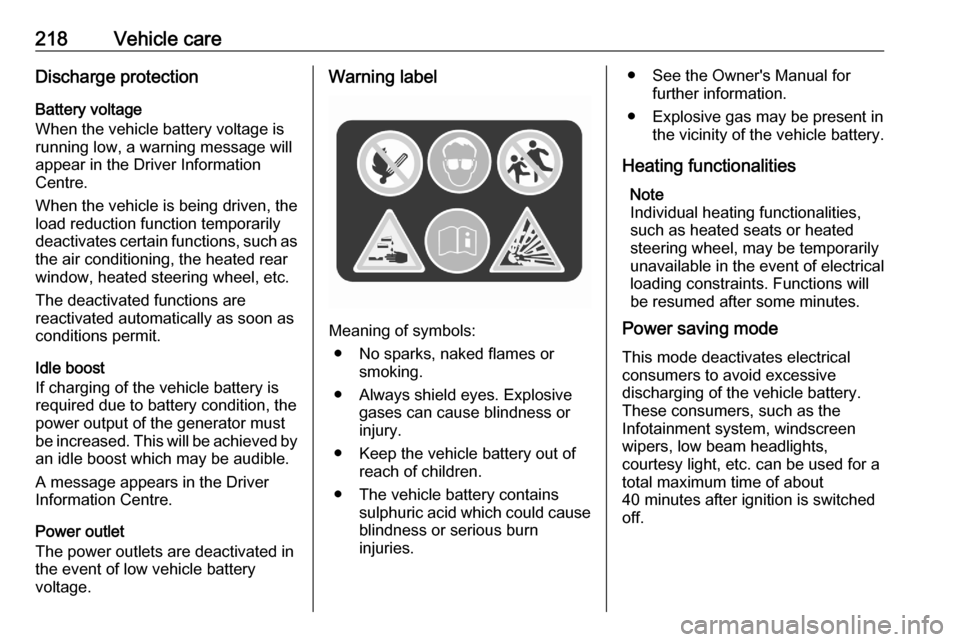
Meaning of symbols:
● No sparks, naked flames or smoking.
● Always shield eyes. Explosive gases can cause blindness or
injury.
● Keep the vehicle battery out of reach of children.
● The vehicle battery contains sulphuric acid which could cause
blindness or serious burn
injuries.
● See the Owner's Manual for further information.
● Explosive gas may be present in the vicinity of the vehicle battery.
Heating functionalities Note
Individual heating functionalities,
such as heated seats or heated
steering wheel, may be temporarily
unavailable in the event of electrical
loading constraints. Functions will
be resumed after some minutes.
Power saving mode
This mode deactivates electrical
consumers to avoid excessive
discharging of the vehicle battery.
These consumers, such as the
Infotainment system, windscreen
wipers, low beam headlights,
courtesy light, etc. can be used for a
total maximum time of about
40 minutes after ignition is switched
off.
Page 234 of 287

232Vehicle careEngine compartment fuse
box
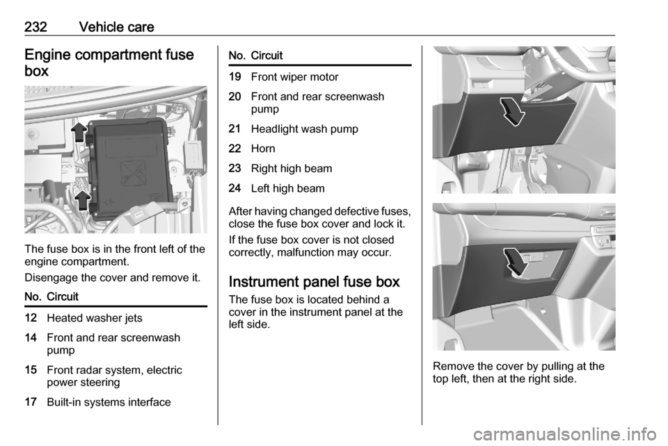
The fuse box is in the front left of the
engine compartment.
Disengage the cover and remove it.
No.Circuit12Heated washer jets14Front and rear screenwash
pump15Front radar system, electric
power steering17Built-in systems interfaceNo.Circuit19Front wiper motor20Front and rear screenwash
pump21Headlight wash pump22Horn23Right high beam24Left high beam
After having changed defective fuses,
close the fuse box cover and lock it.
If the fuse box cover is not closed
correctly, malfunction may occur.
Instrument panel fuse boxThe fuse box is located behind a
cover in the instrument panel at the
left side.
Remove the cover by pulling at the
top left, then at the right side.
Page 235 of 287

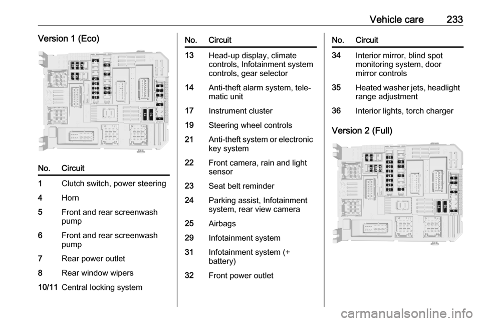
Vehicle care233Version 1 (Eco)No.Circuit1Clutch switch, power steering4Horn5Front and rear screenwash
pump6Front and rear screenwash
pump7Rear power outlet8Rear window wipers10/11Central locking systemNo.Circuit13Head-up display, climate
controls, Infotainment system
controls, gear selector14Anti-theft alarm system, tele‐
matic unit17Instrument cluster19Steering wheel controls21Anti-theft system or electronic key system22Front camera, rain and light
sensor23Seat belt reminder24Parking assist, Infotainment
system, rear view camera25Airbags29Infotainment system31Infotainment system (+
battery)32Front power outletNo.Circuit34Interior mirror, blind spot
monitoring system, door
mirror controls35Heated washer jets, headlight
range adjustment36Interior lights, torch charger
Version 2 (Full)