tow OPEL VIVARO C 2020.25 Manual user
[x] Cancel search | Manufacturer: OPEL, Model Year: 2020.25, Model line: VIVARO C, Model: OPEL VIVARO C 2020.25Pages: 287, PDF Size: 28.79 MB
Page 192 of 287

190Driving and operatingEmergency automatic braking may
slow the vehicle to a complete stop to
try to avoid a potential crash. If the
vehicle comes to a complete stop,
automatic braking is maintained for
up to 2 seconds.
● Automatic transmission: If the vehicle comes to a completestop, keep the brake pedal
depressed to prevent the vehicle
from starting off again.
● Manual transmission: If the vehicle comes to a complete
stop, the engine may stall.
Operation of the function may be felt
by a slight vibration in the brake
pedal.9 Warning
Emergency automatic braking is
an emergency crash preparation
feature and is not designed to
avoid crashes. Do not rely on the
system to brake the vehicle.
Emergency automatic braking will
not brake outside of its operating
speed range and only responds to
detected vehicles and
pedestrians.
System limitations
In some cases, the active emergencybraking system may provide an
automatic braking in situations that
seem to be unnecessary, for instance
in parking garages, due to traffic signs
in a curve or due to vehicles in
another lane. This is normal
operation, the vehicle does not need
service. Firmly apply the accelerator
pedal to override the automatic
braking if the situation and the
surroundings permit.
In the following cases, active
emergency braking performance is
limited:
● Driving on winding or hilly roads.
● Detecting all vehicles, especially vehicles with a trailer, tractors,
muddy vehicles, etc.
● Detecting a vehicle when weather limits visibility, such as infog, rain, or snow.
● Driving during nighttime.
● The windscreen is damaged or affected by foreign items, e.g.
stickers.
Complete attention is always required
while driving, and the driver should be ready to take action and apply the
brakes and / or steer the vehicle to
avoid crashes.
We recommend to deactivate the
system in the vehicle personalisation
in the following cases:
● when towing a trailer or caravan
● when carrying long objects on roof bars or a roof rack
● when the vehicle is being towed with the engine running
● when tyre chains are fitted
● when a spare wheel is fitted that is smaller than the other wheels
● before using an automatic car wash with the engine running
● before placing the vehicle on a rolling road in a workshop
● if the windscreen has been damaged close to the camera
Page 201 of 287
Driving and operating199camera view area, e. g. below the
bumper, or underneath the
vehicle.
Do not drive or park the vehicle
using only the panoramic view
system.
Always check the surrounding of
the vehicle before driving.
Displayed images may be further
or closer than they appear. The
area displayed is limited and
objects that are close to either
edge of the bumper or under the
bumper are not displayed on the
screen.
System limitations
Caution
For optimal operation of the
system, it is important to keep the
lense of the camera in the tailgate between the number plate lightsalways clean. Rinse the lense with water and wipe with a soft cloth.
Do not clean the lense with a
steam-jet or high-pressure jet
cleaner.
The panoramic view system may not
operate properly when:
● The surrounding is dark.
● The sun or the beam of headlights is shining directly into
the camera lenses.
● During nighttime driving.
● Weather limits visibility, such as fog, rain, or snow.
● The camera lenses are blocked by snow, ice, slush, mud, dirt.
● The vehicle is towing a trailer.
● The vehicle had an accident.
● There are extreme temperature changes.
Rear view camera Depending on version, camera is
mounted above the license plate in
the tailgate / left rear door.
9 Warning
The rear view camera does not
replace driver vision. Note that
objects that are outside the
camera's field of view and the
parking assist sensors, e.g. below
the bumper or underneath the
vehicle, are not displayed.
Do not reverse or park the vehicle
using only the rear view camera.
Always check the surrounding of
the vehicle before driving.
The view of the camera is displayed
in the Info Display 3 120 or in the
interior mirror 3 41.
The area displayed by the camera is
limited. The distance of the image that
appears on the display differs from
the actual distance.
Switching on Rear view camera is automatically
activated when reverse gear is
engaged.
Page 202 of 287

200Driving and operatingSwitching off
The camera is switched off when a
forward gear is engaged.
Guidelines
The area behind the vehicle is
displayed in the screen. The vertical
lines represent the width of the
vehicle with mirrors unfolded.
The first horizontal line represents a
distance of about 30 cm beyond the
edge of vehicle's rear bumper. The
upper horizontal lines represent
distances of about 1 and 2 m beyond
the edge of the vehicle's rear bumper.The Guidelines can be deactivated in
the Vehicle personalisation 3 124.
System limitations The rear view camera may not
operate properly when:
● the surrounding is dark
● the beam of headlights is shining
directly into the camera lenses
● weather limits visibility such as fog, rain or snow
● the camera lenses are blocked by snow, ice, slush, mud, dirt.Clean the lense, rinse with water,
and wipe with a soft cloth
● the tailgate will be opened
● the vehicle is towing an electrically connected trailer,bicycle carrier etc.
● the vehicle had a rear end accident
● there are extreme temperature changesLane departure warning
The lane departure warning system
observes the lane markings between
which the vehicle is driving via a front camera. The system detects lane
changes and warns the driver in the
event of an unintended lane change
via visual and acoustic signals.
Criteria for the detection of an
unintended lane change are:
● no operation of turn lights
● no brake pedal operation
● no active acceleration
If the driver is active, no warning will
be issued.
Page 207 of 287
Driving and operating205version, release the fuel filler flap by
pushing the flap or pulling at the right bottom corner.
Depending on the version, place the
key in the lock and unlock the cap.
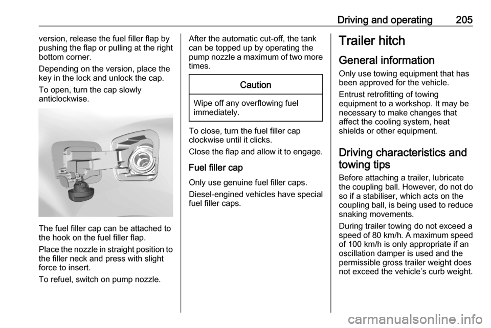
To open, turn the cap slowly
anticlockwise.
The fuel filler cap can be attached to
the hook on the fuel filler flap.
Place the nozzle in straight position to the filler neck and press with slight
force to insert.
To refuel, switch on pump nozzle.
After the automatic cut-off, the tank can be topped up by operating the
pump nozzle a maximum of two more
times.Caution
Wipe off any overflowing fuel
immediately.
To close, turn the fuel filler cap
clockwise until it clicks.
Close the flap and allow it to engage.
Fuel filler cap
Only use genuine fuel filler caps.
Diesel-engined vehicles have special fuel filler caps.
Trailer hitch
General information
Only use towing equipment that has
been approved for the vehicle.
Entrust retrofitting of towing
equipment to a workshop. It may be
necessary to make changes that
affect the cooling system, heat
shields or other equipment.
Driving characteristics and towing tips
Before attaching a trailer, lubricate
the coupling ball. However, do not do so if a stabiliser, which acts on thecoupling ball, is being used to reduce
snaking movements.
During trailer towing do not exceed a
speed of 80 km/h. A maximum speed
of 100 km/h is only appropriate if an
oscillation damper is used and the
permissible gross trailer weight does
not exceed the vehicle’s curb weight.
Page 208 of 287

206Driving and operatingFor trailers with low driving stability
and caravan trailers, the use of an
oscillation damper is strongly
recommended.
If the trailer starts snaking, drive more slowly, do not attempt to correct the
steering and brake sharply if
necessary.
When driving downhill, drive in the
same gear as if driving uphill and
drive at a similar speed.
If the outside temperature exceeds
37 °C, reduce the load on the trailer
to protect the engine of the vehicle.
At high outside temperatures it is
recommended to leave the engine
running for one or two minutes after
having stopped the vehicle in order to
faciliate cooling.
Adjust tyre pressure to the value
specified for full load 3 271.
Towing a trailer increases the braking
distance of the vehicle. To limit the
heating of the brakes, it is
recommended to use the braking
effect of the engine.By driving uphill, the temperature of
the coolant is increased. To reduce
heating, drive at a reduced speed and
pay attention to the coolant
temperature. If the control indicator
2 of the engine coolant temperature
gauge illuminates, stop the vehicle
and switch off engine as soon as
possible.
Trailer towing Trailer loadsThe permissible trailer loads are
vehicle and engine-dependent
maximum values which must not be
exceeded. The actual trailer load is
the difference between the actual
gross weight of the trailer and the
actual coupling socket load with the
trailer coupled.
The permissible trailer loads are
specified in the vehicle documents. In general, they are valid for gradients
up to 12%.
The permissible trailer load applies
up to the specified incline and at sea
level. Since engine power decreases
as altitude increases due to the airbecoming thinner, therefore reducing
climbing ability, the permissible gross
train weight also decreases by 10%
for every 1000 metres of altitude. The gross train weight does not have to be
reduced when driving on roads with
slight inclines (less than 8%, e.g.
motorways).
The permissible gross train weight
must not be exceeded. This weight is
specified on the identification plate
3 264.
When distributing the loads in the trailer, heavy objects should be
placed as close as possible to the
axle.
Vertical coupling load
The vertical coupling load is the load
exerted by the trailer on the coupling
ball. It can be varied by changing the
weight distribution when loading the
trailer.
The maximum permissible vertical
coupling load is specified on the
towing equipment identification plate
and in the vehicle documents.
Page 209 of 287
Driving and operating207Always aim for the maximum vertical
coupling load, especially in the case
of heavy trailers. The vertical coupling
load should never fall below 25 kg.
Rear axle load
When the trailer is coupled and the
towing vehicle fully loaded, the
permissible rear axle load (see
identification plate or vehicle
documents) may be exceeded by
60 kg , the gross vehicle weight rating
must not be exceeded. If the
permissible rear axle load is
exceeded, a maximum speed of
100 km/h applies.
Towing equipment Depending on version the vehicle canbe fitted with a detachable or a fixed
coupling ball bar.
Type ACaution
When operating without a trailer,
remove the coupling ball bar.
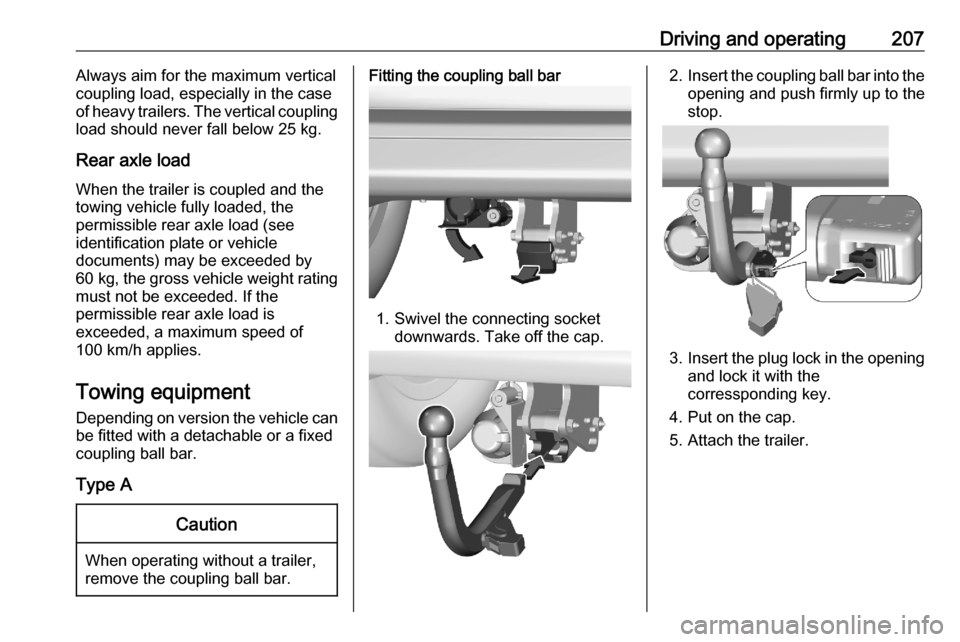
Fitting the coupling ball bar
1. Swivel the connecting socket downwards. Take off the cap.
2.Insert the coupling ball bar into the
opening and push firmly up to the stop.
3. Insert the plug lock in the opening
and lock it with the
corressponding key.
4. Put on the cap.
5. Attach the trailer.
Page 210 of 287
208Driving and operating
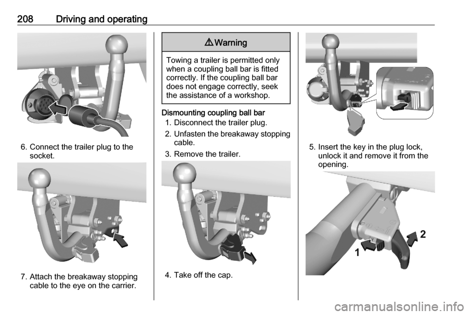
6. Connect the trailer plug to thesocket.
7. Attach the breakaway stoppingcable to the eye on the carrier.
9 Warning
Towing a trailer is permitted only
when a coupling ball bar is fitted correctly. If the coupling ball bardoes not engage correctly, seekthe assistance of a workshop.
Dismounting coupling ball bar
1. Disconnect the trailer plug.
2. Unfasten the breakaway stopping
cable.
3. Remove the trailer.
4. Take off the cap.
5. Insert the key in the plug lock, unlock it and remove it from the
opening.
Page 211 of 287

Driving and operating2096.Move 1 to left and hold it pressed,
push 2 to the back and remove the
coupling ball.
7. Swivel the connecting socket upwards. Put on the cap.
Type B 1. Swivel the connecting socket downwards.
2. Attach the trailer.
3. Connect the trailer plug to the socket and fasten the breakaway
stopping cable to the eye on the
carrier.
Type C
1. Remove the safety splint.
2. Pull the lever and open the towing
ring.
3. Swivel the connecting socket downwards.
4. Attach the trailer, close the towing
ring and fix the splint.
5. Connect the trailer plug to the socket and attach the breakaway
stopping cable to the eye on the
carrier.
Type D 1. Swivel the connecting socket downwards.
2. Attach the trailer.
Page 213 of 287

Vehicle care211Vehicle careGeneral Information...................212
Accessories and vehicle modifications .......................... 212
Vehicle storage ........................212
End-of-life vehicle recovery .....213
Vehicle checks ........................... 213
Performing work ......................213
Bonnet ..................................... 214
Engine oil ................................. 214
Engine coolant ......................... 215
Washer fluid ............................ 216
Brakes ..................................... 216
Brake fluid ............................... 216
Vehicle battery ......................... 217
Diesel fuel system bleeding .....219
Wiper blade replacement ........219
Bulb replacement .......................220
Halogen headlights ..................220
Xenon headlights .....................223
Front fog lights ......................... 224
Front turn lights .......................225
Tail lights ................................. 226
Side turn lights ......................... 228
Centre high-mounted brake light ......................................... 229Number plate light...................230
Interior lights ............................ 230
Electrical system ........................231
Fuses ....................................... 231
Engine compartment fuse box . 232
Instrument panel fuse box .......232
Vehicle tools .............................. 234
Tools ........................................ 234
Wheels and tyres .......................237
Winter tyres ............................. 237
Tyre designations ....................237
Tyre pressure .......................... 237
Tyre deflation detection
system .................................... 238
Tread depth ............................. 239
Changing tyre and wheel size . 240
Wheel covers ........................... 240
Tyre chains .............................. 240
Tyre repair kit .......................... 241
Wheel changing .......................244
Spare wheel ............................ 245
Jump starting ............................. 250
Towing ....................................... 251
Towing the vehicle ...................251
Towing another vehicle ...........252
Appearance care .......................253
Exterior care ............................ 253Interior care............................. 255
Floor mats ............................... 256
Page 214 of 287
212Vehicle careGeneral Information
Accessories and vehicle modifications
We recommend the use of genuine
parts and accessories and factory
approved parts specific for your
vehicle type. We cannot assess or guarantee reliability of other products
- even if they have a regulatory or
otherwise granted approval.
Any modification, conversion or other changes made to standard vehicle
specifications (including, without
limitation, software modifications,
modifications of the electronic control units) may invalidate the warranty
offered by Opel. Furthermore, such
changes may affect driver assistance
systems, may impact fuel
consumption, CO 2 emissions and
other emissions of the vehicle and
cause the vehicle to no longer
conform to the operating permit,
impacting the validity of your vehicle
registration.Caution
When transporting the vehicle on
a train or on a recovery vehicle, the
mud flaps might be damaged.
Cold protection covers
In order to prevent the accumulation
of snow at the radiator cooling fan, it is recommended to install removable
protection covers.
The protection covers must be
professionally installed, consult a
workshop.
Caution
The protection covers must be removed when one of the
following conditions occurs:
● The ambient temperature is above 10 °C.
● When the vehicle is towed.
● The vehicle is driven at speeds
above 120 km/h.
Vehicle storage
Storage for a long period of time If the vehicle is to be stored for several months:
● Wash and wax the vehicle.
● Have the wax in the engine compartment and underbody
checked.
● Clean and preserve the rubber seals.
● Fill up fuel tank completely.
● Change the engine oil.
● Drain the washer fluid reservoir.
● Check the coolant antifreeze and
corrosion protection.
● Adjust tyre pressure to the value specified for full load.
● Park the vehicle in a dry, well ventilated place. Engage first or
reverse gear or set selector lever
to P. Prevent the vehicle from
rolling.
● Do not apply the parking brake.